Contents
- 1. User Manual
- 2. User manual
User Manual
The ConMed Linvatec
26” LCD Medical Monitor
Instruction Manual
(VP4726 and VP4726F)

Proprietary Information
This manual contains information deemed proprietary to Linvatec Corporation. The
information contained herein, including all of the designs and related materials, is the sole
property of ConMed Linvatec and/or its licensors. ConMed Linvatec and/or its licensors
reserve all patent, copyright and other proprietary rights to this document, including all
design, manufacturing methodology and reproduction.
This document, and any related materials, is confidential and is protected by copyright laws
and shall not be duplicated, transmitted, transcribed, stored in a retrieval system, or
translated into any human or computer language in any form or by any means, electronic,
mechanical, magnetic, manual or otherwise, or disclosed to third parties, in whole or in part,
without the prior express written consent of ConMed Linvatec.
ConMed Linvatec reserves the right to revise this publication and to make changes from time
to time in the contents hereof without obligation to notify any person of such revision or
changes, unless otherwise required by law.
Linvatec is a trademark or registered trademark of ConMed Linvatec
Linvatec Corporation 2008. All Rights Reserved. Printed in USA
Record the Model and Serial Numbers of the VP4726 LCD Monitor(s) and date received.
Retain for future reference.
Monitor Model No. Serial No Date
Monitor Model No. Serial No Date
Monitor Model No. Serial No Date

Table of Contents Page
i
1.0 INTRODUCTION
1.1 Intended Use . . . . . . . . . . . . . . . . . . . . . . . . . . . . . . . . . . . . . . . . . . . . . . . . . . . . . . . . .1
1.2 Warnings and Precautions . . . . . . . . . . . . . . . . . . . . . . . . . . . . . . . . . . . . . . . . . . . . . . 1
1.2.1 Warnings . . . . . . . . . . . . . . . . . . . . . . . . . . . . . . . . . . . . . . . . . . . . . . . . . . . . . 1
1.2.2 Precautions. . . . . . . . . . . . . . . . . . . . . . . . . . . . . . . . . . . . . . . . . . . . . . . . . . . . 3
1.3 Environmental Directives . . . . . . . . . . . . . . . . . . . . . . . . . . . . . . . . . . . . . . . . . . . . . . . 4
1.4 Symbol Definitions. . . . . . . . . . . . . . . . . . . . . . . . . . . . . . . . . . . . . . . . . . . . . . . . . . . . 5
1.5 Unpacking and Inspecting the Monitor . . . . . . . . . . . . . . . . . . . . . . . . . . . . . . . . . . . .6
1.6 Returning the Monitor . . . . . . . . . . . . . . . . . . . . . . . . . . . . . . . . . . . . . . . . . . . . . . . . . 6
1.7 System Indicators . . . . . . . . . . . . . . . . . . . . . . . . . . . . . . . . . . . . . . . . . . . . . . . . . . . . . 7
1.7.1 Front Panel On-Screen Display (OSD) Button Functionality . . . . . . . . . . . . . 7
1.7.2 Rear Panel . . . . . . . . . . . . . . . . . . . . . . . . . . . . . . . . . . . . . . . . . . . . . . . . . . . .8
1.8 Monitor Operation . . . . . . . . . . . . . . . . . . . . . . . . . . . . . . . . . . . . . . . . . . . . . . . . . . . . 9
1.9 On-Screen Display Menus . . . . . . . . . . . . . . . . . . . . . . . . . . . . . . . . . . . . . . . . . . . . . 10
1.9.1 DSUB ANALOG/RGBS Input Source . . . . . . . . . . . . . . . . . . . . . . . . . . . . . 10
1.9.2 DVI OPTICAL / DVI DIGITAL Input Source . . . . . . . . . . . . . . . . . . . . . . . 13
1.9.3 YPbPr Input Source . . . . . . . . . . . . . . . . . . . . . . . . . . . . . . . . . . . . . . . . . . . . 15
1.9.4 SVIDEO / CVIDEO Input Source. . . . . . . . . . . . . . . . . . . . . . . . . . . . . . . . . 18
1.9.5 SDI Input Source . . . . . . . . . . . . . . . . . . . . . . . . . . . . . . . . . . . . . . . . . . . . . . 21
1.10 OSD System Overview. . . . . . . . . . . . . . . . . . . . . . . . . . . . . . . . . . . . . . . . . . . . . . . . 24
1.11 Standard Signal Table. . . . . . . . . . . . . . . . . . . . . . . . . . . . . . . . . . . . . . . . . . . . . . . . . 30
1.12 SDI Video Format. . . . . . . . . . . . . . . . . . . . . . . . . . . . . . . . . . . . . . . . . . . . . . . . . . . . 31
1.13 VGA (15 Pin D-Sub) . . . . . . . . . . . . . . . . . . . . . . . . . . . . . . . . . . . . . . . . . . . . . . . . . 31
1.14 DVI In, Out (24 DVI-D). . . . . . . . . . . . . . . . . . . . . . . . . . . . . . . . . . . . . . . . . . . . . . . 32
1.15 C-Video (BNC). . . . . . . . . . . . . . . . . . . . . . . . . . . . . . . . . . . . . . . . . . . . . . . . . . . . . . 32
1.16 S-Video (BNC) . . . . . . . . . . . . . . . . . . . . . . . . . . . . . . . . . . . . . . . . . . . . . . . . . . . . . . 33
1.17 RS232C (D-SUB 9 Pin) . . . . . . . . . . . . . . . . . . . . . . . . . . . . . . . . . . . . . . . . . . . . . . . 33
1.18 SDI (BNC) . . . . . . . . . . . . . . . . . . . . . . . . . . . . . . . . . . . . . . . . . . . . . . . . . . . . . . . . . 33
1.19 RGBHV / RGBS / YPbPr (BNC). . . . . . . . . . . . . . . . . . . . . . . . . . . . . . . . . . . . . . . . 34
1.20 OPTICAL (available on VP4726F Monitor Only). . . . . . . . . . . . . . . . . . . . . . . . . . . 34

ii
Table of Contents Page
2.0 MAINTENANCE
2.1 Life Expectancy . . . . . . . . . . . . . . . . . . . . . . . . . . . . . . . . . . . . . . . . . . . . . . . . . . . . . 35
2.2 Periodic Maintenance. . . . . . . . . . . . . . . . . . . . . . . . . . . . . . . . . . . . . . . . . . . . . . . . . 35
2.3 Cleaning Instructions . . . . . . . . . . . . . . . . . . . . . . . . . . . . . . . . . . . . . . . . . . . . . . . . . 35
2.4 Recommended Annual Monitor Maintenance Requirements . . . . . . . . . . . . . . . . . . 36
2.5 Technical Specifications. . . . . . . . . . . . . . . . . . . . . . . . . . . . . . . . . . . . . . . . . . . . . . . 38
2.6 Detailed EMC Information. . . . . . . . . . . . . . . . . . . . . . . . . . . . . . . . . . . . . . . . . . . . . 41
2.7 Obtaining Parts and Accessories . . . . . . . . . . . . . . . . . . . . . . . . . . . . . . . . . . . . . . . . 47
2.8 Customer Service . . . . . . . . . . . . . . . . . . . . . . . . . . . . . . . . . . . . . . . . . . . . . . . . . . . . 48
2.8.1 Assistance . . . . . . . . . . . . . . . . . . . . . . . . . . . . . . . . . . . . . . . . . . . . . . . . . . . 48
2.8.2 Repairs. . . . . . . . . . . . . . . . . . . . . . . . . . . . . . . . . . . . . . . . . . . . . . . . . . . . . . 48
1
1.0 INTRODUCTION
t is recommended that personnel study this
manual before attempting to connect,
operate, adjust and/or clean the ConMed
Linvatec VP4726 and VP4726F Medical LCD
26” Monitors. The safe and effective use of this
equipment requires the understanding of and
compliance with all warnings, precautionary
notices, and instructions marked on the product,
and included in this manual.
The VP4726F Monitor is identical to the
VP4726 Monitor except it is equipped with
Optical input connectors. See “1.20 OPTICAL
(available on VP4726F Monitor Only)” on
page 34 for connector information.
1.1 Intended Use
The VP4726 and VP4726F Medical LCD 26”
Monitors are used to display live and recorded
images captured with a medical grade camera
system or previously recorded using various
recording devices.
1.2 Warnings and Precautions
The words WARNING, PRECAUTION, and
NOTE carry special meanings and they should
be read carefully.
WARNING: The safety and/or health
of the patient, user, or a third party is at
risk. Comply with this warning to avoid
injury to the patient, user, or third party.
PRECAUTION: This contains
information concerning the intended use
of the device or accessory. Damage to
the equipment is possible if these instructions
are not followed.
NOTE: A note is added to provide additional,
focused, information.
1.2.1 Warnings
1. This equipment is designed for use
by medical professionals completely familiar
with the required techniques and instructions
for use of the equipment. Prior to using the
device, read and follow all warning and
precautionary notices and instructions
marked on the product and included in
this manual.
2. Do not attempt to open or service
the monitor, as this may void your
warranty. There are no user-
serviceable parts inside. Removing
the cover may introduce an electric
shock hazard by exposing you to dangerous
high voltages or other risks. If the system
malfunctions, return it for service
immediately.
I
2
3. Dangerous voltages are present
inside the monitor. The unit should
be used only in rooms that comply
with recommendations concerning
electrical safety when used for medical
purposes (as stated in IEC 60601 Series and
UL 60601-1).
4. Never insert anything metallic into
the cabinet openings of the monitor.
Doing so may cause electric shock.
5. System installation shall be in accordance
with the requirements of IEC 60601-1-1,
The Standard for Safety Requirements of
Medical Electrical Systems.
6. This equipment is not suitable for
use in the presence of flammable
anesthetic mixture with air,
oxygen, or nitrous oxide.
7. Some disinfectants and cleaning agents
vaporize to form explosive mixtures and, if
such agents are used, the vapor must be
allowed to disperse before the monitor is
put to use.
8. Before connecting the AC power cord to
the DC adapter outlet make sure the voltage
designation of the DC adapter corresponds
to the local electrical supply.
9. Disconnect monitor prior to applying
cardiac defibrillation to patient.
10. This monitor should not share an electrical
outlet or grounding with life supporting or
life sustaining equipment.
11. This monitor may not be used in connection
with life support equipment.
12. Equipment grounding is vital for safe
operation. Plug power cord into a properly
earthed mains supply outlet whose voltage
and frequency characteristics are
compatible with those listed on the monitor
or in this manual. Do not use plug adapters
or extension cords; such devices defeat the
safety ground and could cause injury.
13. Grounding reliability is achieved only when
the monitor is connected to a “hospital
only” or “hospital grade” receptacle.
Inspect routinely and do not use if damage
is discovered.
14. If one or more mains powered units are
connected simultaneously to one socket by
the means of a distribution box, the sum of
the individual leakage currents may exceed
the tolerated limits.
15. Be sure to hold the plug, not the
cord, when disconnecting the
monitor from an electric socket.
Doing so may cause electric shock.
16. Do not touch signal input, signal output or
other connectors, and the patient
simultaneously.
17. If your monitor does not operate normally,
in particular, if there are any unusual
sounds or smells coming from it, unplug it
immediately and return for service.
18. For the protection of service personnel, and
for safety during transportation, all devices
and accessories that are returned for repair
must be prepared for shipment as described
in “1.6 Returning the Monitor” on page 6
of this manual. The manufacturer has the
right to refuse to carry out repairs if the
product is contaminated.
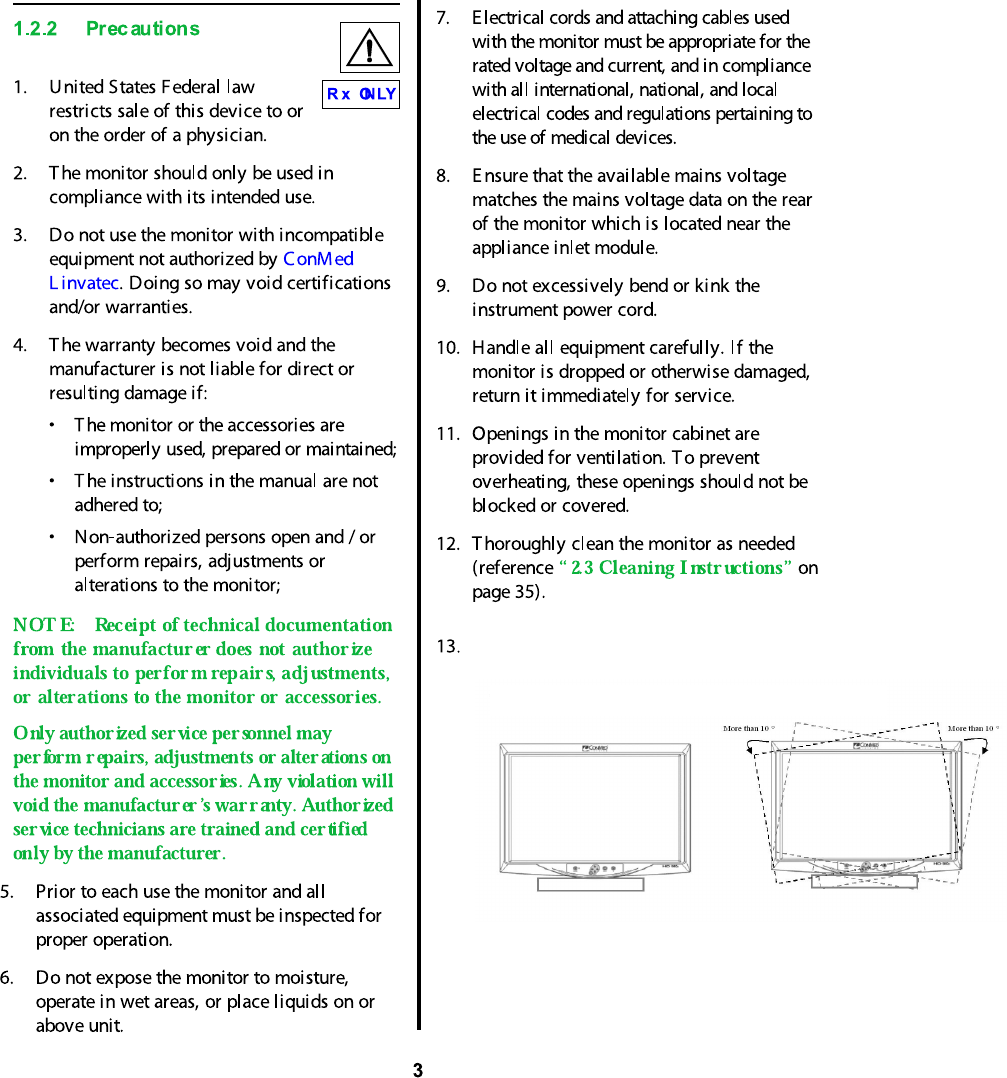
To
14. Using Plug for US: 120V rating -5-15P type only
Caution: Make sure the power cord is the correct type that is required in your area.
This LCD monitor has a universal power supply that allows operation in either 100-120V
AC or 200-240V AC voltage areas (no user adjustment is required).
avoid injury by tipping over, set the monitor to the following
tilted position before moving.

4
15. External equipment that will be connected to
signal input and signal output ports or other
connectors shall comply with relevant IEC
standard (i.e., IEC 60950 for IT equipment
and IEC 60601 series for medical electrical
equipment) . In addition, all such
combinations / systems - shall comply with
the standard IEC 60601-1-1 (Safety
requirements for medical electrical systems).
Any person who connects ex ternal
equipment to signal input and signal output
ports or other connectors has formed a
system and is therefore responsibl e for the
system to comply with the requirements of
IEC 60601-1-1. If in doubt, contact a
qualified technician or your local
representative.
(a)Reorient or relocate the receiving
device.
(b)Increase the separati on between the
equipment.
(c)Connect the equipment into an outlet
on a circuit di fferent from that to which
the other devices are connected.
(d)Consult the manufacturer or field
service technician for assistance.
1.3Environmental Directives
WE E E Dir ective [2002/96/E C] on
W aste E lectrical and Electr onic
E quipmen t
The Directive on Waste Electrical and
Electronic Equipment obliges manufacturers,
importers, and/or di stributors of electronic
equipment to provide for recycling of the
electronic equipment at the end of its useful life.
Do not di spose of WEEE in unsorted municipal
waste.
The WEEE symbol on the product or its
packaging indicates that this product must not
be di sposed of with other waste. Instead, it is
your responsibility to dispose of your waste
equipment by handing it over to a designated
collection point for the recycling of Waste
Electrical and Electronic Equipment. The
separate collection and recycling of your waste
equipment at the time of disposal will help
conserve natural resources and ensure that it is
recycled in a manner that protects human health
and the environment. For more information
about where you can drop off your medi cal
equipment at the end of its useful life for
recycling, please contact ConM ed Linvatec.
Use the proper power cord with correct attachment
plug type. If the power source is 120 V AC, use a
power cord which is a Hospital Grade Power Cord
with NEMA 5-15 style plug, labeled for 125 volts AC
with UL and C-UL approvals. If the power source is
a 240 V AC supply, use the tandem (T blade) type
attachment plug with ground conductor power cord
that meets the respective European country's safety
regulations.
The hospital-grade plug for medical products
intended for use in Denmark has DEMKO approval
and is rated 13 amps at 250Vac. Plug is
recommended for use in medical applications and
specifications are being added to the standard
SB 107-2-D1.
Plug mates with maker's Danish hospital-grade
socket. Hospital sockets have slightly different
shaped openings allowing only the hospital plug,
not the standard Danish plug, to be inserted, to
protect the ac circuit in specific medical settings.
5
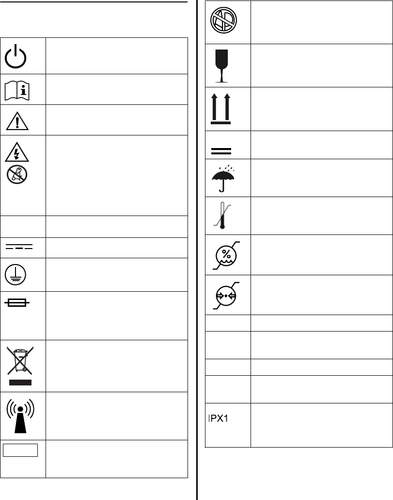
1.4Symbol Definitions
Power Standby / ON
F ollow instr uctions for use.
Precaution or warning notice
E lec tr ical hazard. Danger ous
voltages are pr esent within the
cabinet. Nev er attempt to r epair
the eq uipmen t. Only trained
ser vice per sonnel may rem ov e
the cover, or obtain access to the
system components.
Alter nating C ur r ent.
Dir ect Current
Protec tive E arth (gr ou nd).
W ar ning - F or continued
pr ot ec tion aga inst risk of fire,
replace on ly with same type and
rating fuse.
W aste E lec tronics and E lectr ical
E quipment (WE E E ) Symbol.
R ega r ding E uropean Union end-
of -life of product.
R F Symbol. Non-ionizing
E lec tr omagnetic R adiation
C aution: Fed er al L aw res tr icts
this dev ice to sale by or on the
or der of a physician.
~
R x ONLY
F lammable Anesthetics - Risk of
ex plosion if used in the presence of
flammable anesthetics
F ragile
T his side up
M aximum Stacking
Keep Dry
T emperatur e limits for stor age and
transpor t
H umidity limits for stor age and
transpor t
Pressur e limits for stor age and
transpor t
GPIO G ener al Pur pose I nput / Output
PACS Picture A rchive C ommunications
System
PIPPictur e in Pictur e
PBPPi
I ndicates that the device is
protected against the effects
of ver tically falling water "
cture B y Pictur e (side by side
images)
3

6
1.5 Unpacking and Inspecting the
Monitor
Upon receipt, carefully unpack the monitor and
accessories. Ensure contents are complete and
are free from damage. If any damage is noted
contact your ConMed Linvatec Customer
Service. Save ALL packaging materials; they
may be needed to verify any claims of damage
by the shipper.
VP4726 / VP4726F LCD 26” Monitor:
• 1 - DVI Cable, 6 ft. (IM9021)
• 1 - BNC Cable (8175-06)
• 1 - S-Video (Y/C) Cable (8149-06)
• 1 - AC Adapter (023933)
• 2 - DC Cable Terminal male / female
(Optional)
• 1 - Screws FH M3x5 (Optional)
• 1 - Instruction Manual
The power cord is sold separately and is
packaged in a separate box.
• C7104 Power Cord — 115VAC
• C7105 Power Cord — 230VAC
1.6 Returning the Monitor
If it becomes necessary to return the monitor,
always use the original packaging. The
manufacturer does not take responsibility for
damage that has occurred during transportation
if the damage was caused by inadequate
transport packaging.
Contact the Manufacturer for Return
Authorization PRIOR to shipping your monitor
for service.
Please make sure that all required information
has been supplied.
• Owner’s Name
• Owner’s Address
• Owner’s Daytime Telephone Number
• Device type and model.
• Serial Number
• Detailed explanation of the damage.
7
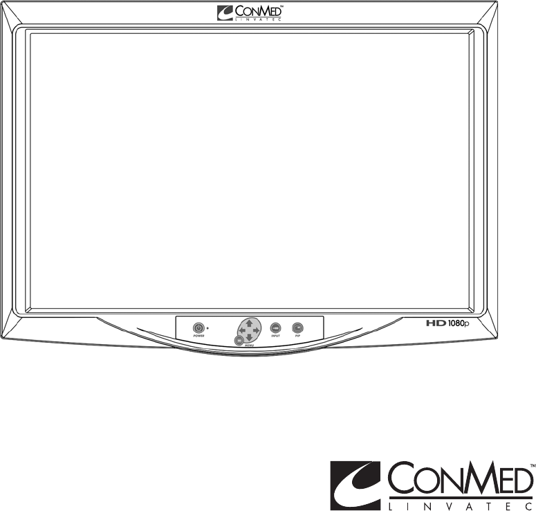
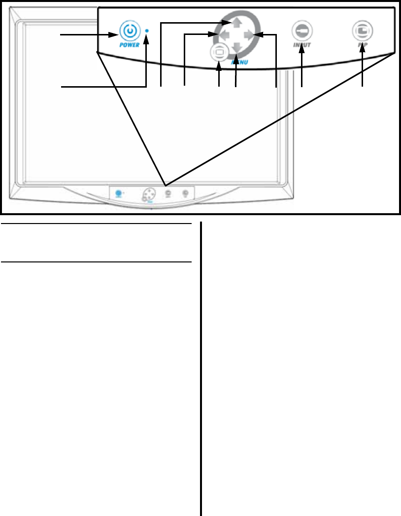
1.7 System Indicators
1.7.1 Front Panel On-Screen Display
(OSD) Button Functionality
❶“POWER” Button - Press to set the
monitor to Normal Mode or Stand-by Mode.
❷Power Status Indicator - Indicator is
illuminated green when monitor is in stand-
by mode, and is off when the monitor is
activated.
❸Up Arrow - With the OSD deactivated, press
this area to increase the brightness of the
monitor. With the OSD activated, press this
area to move the cursor upward in a menu.
❹Left Arrow - With the OSD deactivated,
press this area to decrease the contrast of
the monitor. With the OSD activated, press
this area to enter a sub-menu and decrease
the adjustment of the selected function.
➎MENU Button - With the OSD deactivated,
pressing this button activates the OSD menu.
With OSD activated, pressing this button
exits the main menu or sub-menu.
➏Down Arrow - With the OSD deactivated,
press this area to decrease the brightness of
the monitor. With the OSD activated, press
this area to move the cursor downward.
❼Right Arrow - With the OSD deactivated,
press this area to increase the contrast of the
monitor. With the OSD activated, press this
area to enter a sub-menu and increase the
adjustment of the selected function.
❽INPUT Button - Used to change the
monitor’s signal source; select DVI
OPTICAL / DVI DIGITAL / DSUB
ANALOG / SDI YPbPR / RGBS / SVIDEO
/ CVIDEO. With OSD deactivated, press
this button to switch signal inputs.
➒PIP Button - Pressing this button enables
the Picture-In-Picture function. Select PIP,
PBP1, PBP2.
❶
❸❹ ❺
❻❼❽ ❾
❷
8
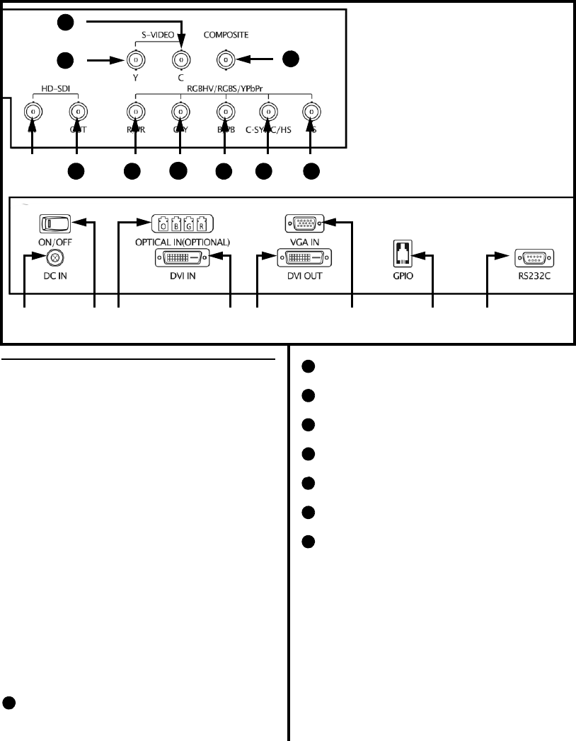
1.7.2 Rear Panel
❶AC / DC IN Jack
❷ON / OFF Switch
❸OPTICAL IN (OPTIONAL) Connector
(Available only on the VP4726F Model)
❹DVI IN Connector
➎DVI OUT Connector
➏VGA IN Connector
❼GPIO Connector
❽RS232C Connector
➒HD SDI IN Connector
➓HD SDI OUT Connector
RED / Pr Connector
GREEN / Y Connector
BLUE / Pb Connector
C-SYNC / H-SYNC Connector
VS (V-SYNC) Connector
S-VIDEO / Y Connector
S-VIDEO / C Connector
Composite (C) VIDEO Connector
11
12
13
14
15
16
17
18
❶❷❸ ❹❺ ❻❼❽
❾
10 11
12
13 14 15
17
18
16

9
1.8 Monitor Operation
1. Connect the DC input jack to the DC IN
connector on the back of the monitor.
2. Plug the female end of the AC Power Cord
into the AC Inlet of the DC Adapter.
3. Plug the AC Power Cord into a Hospital
Grade outlet.
4. Connect the appropriate video source to the
monitor.
5. Apply power to all connected peripheral
devices.
6. Turn the monitor on by pressing the power
switch on the back of the monitor.
7. Set your preferred settings using the On-
Screen Menus listed on the following
pages.
10
1.9 On-Screen Display Menus
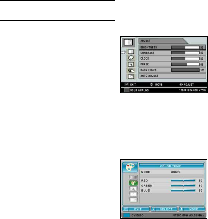
1.9.1 DSUB ANALOG/RGBS Input Source
Adjust Menu
❶BRIGHTNESS - Increase or decrease the
brightness (Range: 0~100).
❷CONTRAST - Increase or decrease the contrast
(Range: 0~100).
❸CLOCK - Increase or decrease the sampling
frequency (Range: 0~100).
❹PHASE - Increase or decrease the phase level
(Range: 0~100).
➎BACK LIGHT - Increase or decrease the back
light dimming level (Range: 0~100).
➏AUTO ADJUST - Fit to the most appropriate
screen on the D-SUB Analog signal.
Color Temp Menu
❶MODE - Change the color temperature mode: C1,
C2, USER. When USER is selected, a sub-menu
displays allowing the user to adjust the RED,
GREEN or BLUE balance.
❷RED - Red balance- Only works with USER mode
(Range: 0~100).
❸GREEN - Green balance- Only works with USER
mode (Range: 0~100).
❹BLUE - Blue balance- Only works with USER
mode (Range: 0~100).
11
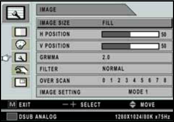
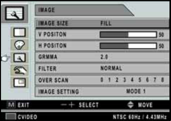
Image Menu
❶IMAGE SIZE - Change the image size (Scaling
mode) (Full; Fill aspect, 1:1; Normal; Video;
Zoom; Video only).
❷H POSITION - Adjust the horizontal (left or right)
position of the displayed source image
(Range: 0~100).
❸V POSITION - Adjust the vertical (up or down)
position of the displayed source image
(Range: 0~100).
❹GAMMA - Adjust GAMMA value (VIDEO,
BYPASS, 1.8, 2.0, 2.2, 2.4, 2.6, PACS).
➎FILTER - Set the sharpness of the image (Softest,
Soft, Normal, Sharp, Sharpest).
➏OVER SCAN - Adjust the displayed size ( 0~8)
❼IMAGE SETTING - Allow selection of one of
five user defined image presets.
12
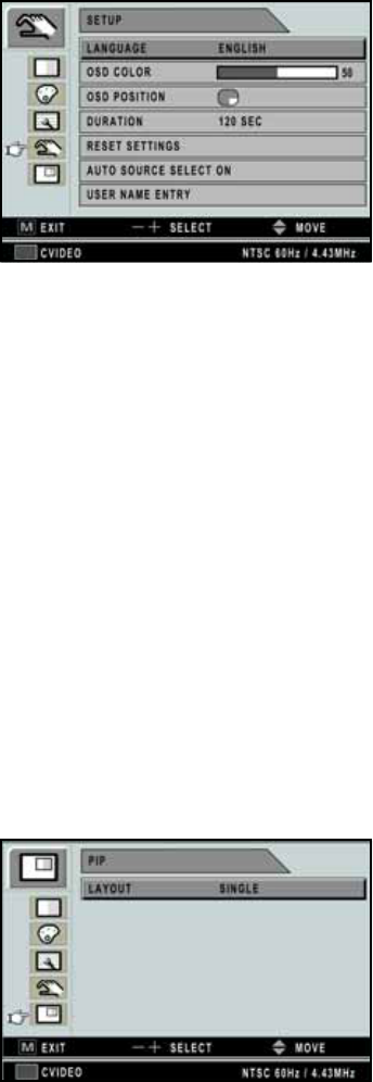
Setup Menu
❶LANGUAGE - Change the OSD language
(8 languages - Korean, English, French, Spanish,
German, Chinese, Japanese, Italian).
❷OSD COLOR - Adjust the OSD background from
white opaque to half translucent.
❸OSD POSITION - Change the OSD position.
❹DURATION - Adjust time until the OSD Menu
will disappear after adjusting the duration
(5, 10, 20, 30, 60, 90, 120, 180, 240 seconds).
➎RESET SETTINGS - Changes all the OSD values
to factory out-going status.
➏AUTO SOURCE SELECT - Disable or enable
auto source select. (ON: Searches through all
possible input sources until an active video source
is found. OFF: Video input is manually selected.)
❼USER NAME ENTRY - Change the name of a
Preset to the Users Name, etc.
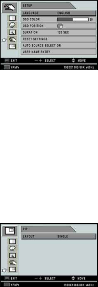
PIP Menu
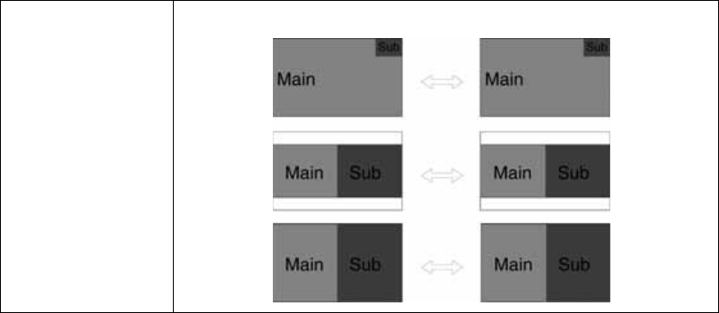
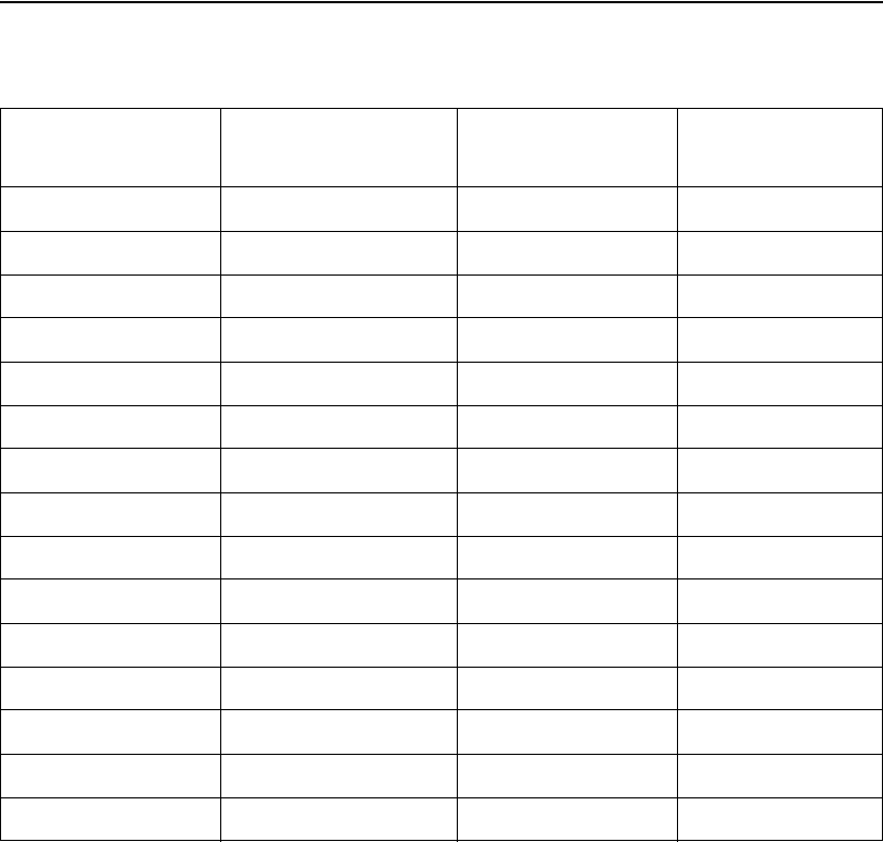
❶LAYOUT - Changes the OSD layout (Single, PIP,
PBP1, PBP2).
The following are Sub-menus under LAYOUT;
❷SOURCE - Changes the secondary source.
❸SWAP - Swaps the position and size of the Primary
and Secondary image.
13
1.9.2 DVI OPTICAL / DVI DIGITAL Input
Source
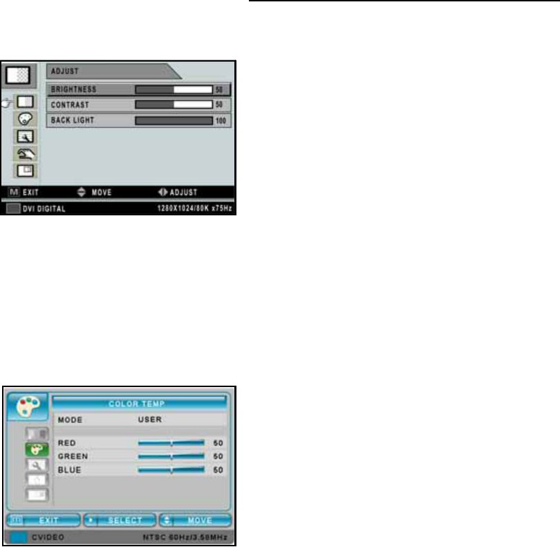
Adjust Menu
❶BRIGHTNESS - Increase or decrease the
brightness (Range: 0~100).
❷CONTRAST - Increase or decrease the contrast
(Range: 0~100).
❸BACK LIGHT - Adjust the back light dimming
level (Range: 0~100).
Color Temp Menu
❶MODE - Change the color temperature mode: C1,
C2, USER. When USER is selected, a sub-menu
displays allowing the user to adjust the RED,
GREEN or BLUE balance.
❷RED - Red balance- Only works with USER mode
(Range: 0~100).
❸GREEN - Green balance- Only works with USER
mode (Range: 0~100).
❹BLUE - Blue balance- Only works with USER
mode (Range: 0~100).
14
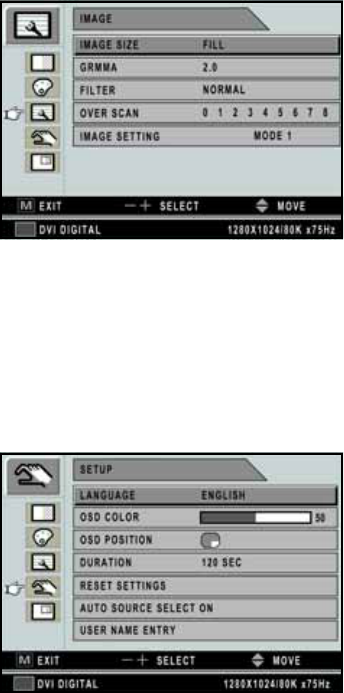
Image Menu
❶IMAGE SIZE - Change the image size
(Scaling mode) (Full; Fill aspect, 1:1; Normal;
Anamorphic).
❷GAMMA - Adjust GAMMA value (VIDEO,
BYPASS, 1.8, 2.0, 2.2, 2.4, 2.6, PACS).
❸FILTER - Set the sharpness of the image (Softest,
Soft, Normal, Sharp, Sharpest).
❹OVER SCAN - Adjust the displayed size ( 0~8).
➎IMAGE SETTING - Change the image setting
(MODE, 1, 2, 3, 4, 5).
Setup Menu
❶LANGUAGE - Change the OSD language
(8 languages - Korean, English, French, Spanish,
German, Chinese, Japanese, Italian).
❷OSD COLOR - Adjust the OSD background from
white opaque to half translucent.
❸OSD POSITION - Change the OSD position
(9 Positions).
❹DURATION - Adjust time until the OSD Menu
will disappear after adjusting the duration
(5, 10, 20, 30, 60, 90, 120, 180, 240 seconds).
➎RESET SETTINGS - Changes all the OSD values
to factory out-going status.
➏AUTO SOURCE SELECT - Disable or enable
auto source select. (ON: Searches through all
possible input sources until an active video source
is found. OFF: Video input is manually selected.)
❼USER NAME ENTRY - Change the name of a
Preset to the Users Name, etc.
15
PIP Menu
❶LAYOUT - Changes the OSD layout (Single, PIP,
PBP1, PBP2).
The following are Sub-menus under LAYOUT;
❷SOURCE - Changes the secondary source.
❸SWAP - Swaps the position and size of the Primary
and Secondary image.
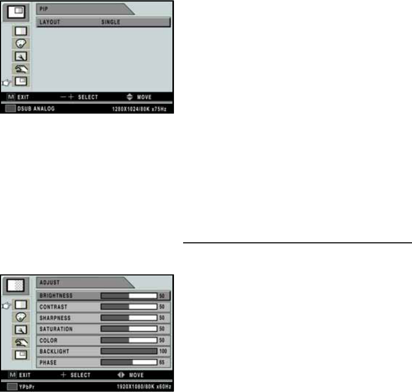
1.9.3 YPbPr Input Source
Adjust Menu
❶BRIGHTNESS - Increase or decrease the
brightness (Range: 0~100).
❷CONTRAST - Increase or decrease the contrast
(Range: 0~100).
❸SHARPNESS - Adjust the sharpness of the video
image (Range: 0~100).
❹SATURATION - Changes the tone of the color
(Range: 0~100).
➎COLOR - Changes the richness of the color
(Range: 0~100).
➏BACK LIGHT - Increase or decrease the back
light dimming level (Range: 0~100).
❼PHASE - Increase or decrease the phase level
(Range: 0~100).
16
Color Temp Menu
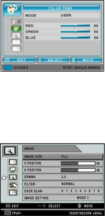
❶MODE - Change the color temperature mode: C1,
C2, USER. When USER is selected, a sub-menu
displays allowing the user to adjust the RED,
GREEN or BLUE balance.
❷RED - Red balance- Only works with USER mode
(Range: 0~100).
❸GREEN - Green balance- Only works with USER
mode (Range: 0~100).
❹BLUE - Blue balance- Only works with USER
mode (Range: 0~100).
Image Menu
❶IMAGE SIZE - Change the image size
(Scaling mode) (Full; Fill aspect, 1:1; Normal;
Video; Zoom; Video only).
❷V POSITION - Adjust the vertical (up or down)
position of the displayed source image
(Range: 0~100).
❸H POSITION - Adjust the horizontal (left or right)
position of the displayed source image
(Range: 0~100).
❹GAMMA - Adjust GAMMA value (VIDEO,
BYPASS, 1.8, 2.0, 2.2, 2.4, 2.6, PACS).
➎FILTER - Set the sharpness of the image (Softest,
Soft, Normal, Sharp, Sharpest).
➏OVER SCAN - Adjust the displayed size ( 0~8)
❼IMAGE SETTING - Change the image setting
(Mode 1, 2, 3, 4, 5).
17
Setup Menu
❶LANGUAGE - Change the OSD language
(8 languages - Korean, English, French, Spanish,
German, Chinese, Japanese, Italian).
❷OSD COLOR - Adjust the OSD background from
white opaque to half translucent.
❸OSD POSITION - Change the OSD position
(9 Positions).
❹DURATION - Adjust time until the OSD Menu
will disappear after adjusting the duration
(5, 10, 20, 30, 60, 90, 120, 180, 240 seconds).
➎RESET SETTINGS - Changes all the OSD values
to factory out-going status.
➏AUTO SOURCE SELECT - Disable or enable
auto source select. (ON: Searches through all
possible input sources until an active video source
is found. OFF: Video input is manually selected.)
❼USER NAME ENTRY - Change the name of a
Preset to the Users Name, etc.
PIP Menu
❶LAYOUT - Changes the OSD layout (Single, PIP,
PBP1, PBP2).
The following are Sub-menus under LAYOUT;
❷SOURCE - Changes the secondary source.
❸SWAP - Swaps the position and size of the Primary
and Secondary image.
18
1.9.4 SVIDEO / CVIDEO Input Source
Adjust Menu
❶BRIGHTNESS - Increase or decrease the
brightness (Range: 0~100).
❷CONTRAST - Increase or decrease the contrast
(Range: 0~100).
❸SHARPNESS - Adjust the sharpness of the video
image (Range: 0~100).
❹SATURATION - Changes the tone of the color
(Range: 0~100).
➎COLOR - Changes the richness of the color
(Range: 0~100).
➏BACK LIGHT - Increase or decrease the back
light dimming level (Range: 0~100).
Color Temp Menu
❶MODE - Change the color temperature mode: C1,
C2, USER. When USER is selected, a sub-menu
displays allowing the user to adjust the RED,
GREEN or BLUE balance.
❷RED - Red balance- Only works with USER mode
(Range: 0~100).
❸GREEN - Green balance- Only works with USER
mode (Range: 0~100).
❹BLUE - Blue balance- Only works with USER
mode (Range: 0~100).
19
Image Menu
❶IMAGE SIZE - Change the image size
(Scaling mode) (Full; Fill aspect, 1:1; Normal;
Video; Zoom; Video only).
❷V POSITION - Adjust the vertical (up or down)
position of the displayed source image
(Range: 0~100).
❸H POSITION - Adjust the horizontal (left or right)
position of the displayed source image
(Range: 0~100).
❹GAMMA - Adjust GAMMA value (VIDEO,
BYPASS, 1.8, 2.0, 2.2, 2.4, 2.6, PACS).
➎FILTER - Set the sharpness of the image (Softest,
Soft, Normal, Sharp, Sharpest).
➏OVER SCAN - Adjust the displayed size ( 0~8)
❼IMAGE SETTING - Change the image setting
(Mode 1, 2, 3, 4, 5).
20
Setup Menu
❶LANGUAGE - Change the OSD language
(8 languages - Korean, English, French, Spanish,
German, Chinese, Japanese, Italian).
❷OSD COLOR - Adjust the OSD background from
white opaque to half translucent.
❸OSD POSITION - Change the OSD position
(9 Positions).
❹DURATION - Adjust time until the OSD Menu
will disappear after adjusting the duration
(5, 10, 20, 30, 60, 90, 120, 180, 240 seconds).
➎RESET SETTINGS - Changes all the OSD values
to factory out-going status.
➏AUTO SOURCE SELECT - Disable or enable
auto source select. (ON: Searches through all
possible input sources until an active video source
is found. OFF: Video input is manually selected.)
❼USER NAME ENTRY - Change the name of a
Preset to the Users Name, etc.
PIP Menu
❶LAYOUT - Changes the OSD layout (Single, PIP,
PBP1, PBP2).
The following are Sub-menus under LAYOUT;
❷SOURCE - Changes the secondary source.
❸SWAP - Swaps the position and size of the Primary
and Secondary image.
21
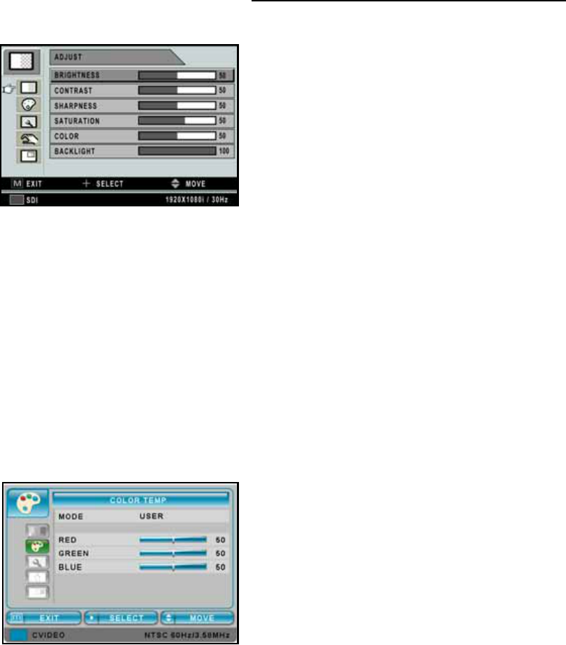
1.9.5 SDI Input Source
Adjust Menu
❶BRIGHTNESS - Increase or decrease the
brightness (Range: 0~100).
❷CONTRAST - Increase or decrease the contrast
(Range: 0~100).
❸SHARPNESS - Adjust the sharpness of the video
image (Range: 0~100).
❹SATURATION - Changes the tone of the color
(Range: 0~100).
➎COLOR - Changes the richness of the color
(Range: 0~100).
➏BACK LIGHT - Increase or decrease the back
light dimming level (Range: 0~100).
Color Temp Menu
❶MODE - Change the color temperature mode: C1,
C2, USER. When USER is selected, a sub-menu
displays allowing the user to adjust the RED,
GREEN or BLUE balance.
❷RED - Red balance- Only works with USER mode
(Range: 0~100).
❸GREEN - Green balance- Only works with USER
mode (Range: 0~100).
❹BLUE - Blue balance- Only works with USER
mode (Range: 0~100).
22
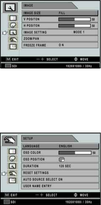
Image Menu
❶IMAGE SIZE - Change the image size
(Scaling mode) (Full; Fill aspect, 1:1; Normal;
Video; Zoom; Video only).
❷V POSITION - Adjust the vertical (up or down)
position of the displayed source image
(Range: 0~100).
❸H POSITION - Adjust the horizontal (left or right)
position of the displayed source image
(Range: 0~100).
❹IMAGE SETTING - Change the image setting
(Mode 1, 2, 3, 4, 5).
➎ZOOM / PAN - Enlarge the image.
➏FREEZE FRAME - Freezes the image.
Setup Menu
❶LANGUAGE - Change the OSD language
(8 languages - Korean, English, French, Spanish,
German, Chinese, Japanese, Italian).
❷OSD COLOR - Adjust the OSD background from
white opaque to half translucent.
❸OSD POSITION - Change the OSD position
(9 Positions).
❹DURATION - Adjust time until the OSD Menu
will disappear after adjusting the duration
(5, 10, 20, 30, 60, 90, 120, 180, 240 seconds).
➎RESET SETTINGS - Changes all the OSD values
to factory out-going status.
➏AUTO SOURCE SELECT - Disable or enable
auto source select. (ON: Searches through all
possible input sources until an active video source
is found. OFF: Video input is manually selected.)
❼USER NAME ENTRY - Change the name of a
Preset to the Users Name, etc.

23
PIP Menu
❶LAYOUT - Changes the OSD layout (Single, PIP,
PBP1, PBP2).
The following are Sub-menus under LAYOUT;
❷SOURCE - Changes the secondary source.
❸SWAP - Swaps the position and size of the Primary
and Secondary image.
24
1.10 OSD System Overview
MENUS FUNCTION DESCRIPTION
BRIGHTNESS Press the BRIGHTNESS button to display the ADJUST menu or the UP/
DOWN arrows
Setting the brightness too high will cause the image to bloom or flare, too
low will decrease the visible light
CONTRAST Press the CONTRAST button to display the ADJUST menu or the
+ / - arrows
Setting the Contrast too high or too low will causes loss of some grayscales.
BACKLIGHT Press the BACKLIGHT button to display the ADJUST menu. Setting the
backlight too low will cause a dark image and too high will decrease the
backlight lifetime.
AUTO ADJUST Press the BACKLIGHT button to display the ADJUST menu or SOURCE
hot key.
SHARPNESS Adjusts the sharpness of the video image
SATURATION Changes the tone of the color
COLOR Change the tone richness of the color
COLOR TEMP C1 Default 6500K color setting
COLOR TEMP C2 Default 9300K color setting
COLOR TEMP
USER
Default 7200K color setting. When USER is selected, Red, Green and
Blue values are changeable by the user.
H POSITION Adjusts the Horizontal (left / right) position of the image. It will return to
the default state when executing AUTO ADJUST OR RESET SETTINGS
V POSITION Adjusts the Vertical (up / down) position of the image. It will return to the
default state when executing AUTO ADJUST OR RESET SETTINGS
25
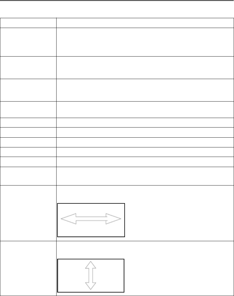
IMAGE SIZE DSUB/ DVI OPTICAL / DVI DIGITAL input source
GAMMA Adjusts the gamma curve of the video image
FILTER Adjusts the sharpness of the video image
FULL FILL ASPECT
1:1 NORMAL CAUTION: FILL ASPECT,
YPbPr / RGBS / SDI / CVIDEO / SVIDEO input source
FULL
NORMAL Size are dependent
on input size ratio
1:1FILL ASPECT
1:1 NORMAL
1.8 2.0 2.2 2.4 2.6 PACS VIDEO
26
OVER SCAN Enable 10% over scan of the original input image
IMAGE SETTING Allows the selection of one of five user defined image presets
FREEZE FRAME Freezes the main image. Does not support secondary image freeze at PIP mode
LANGUAGE Changes the OSD language (8 languages). ENGLISH / GERMAN /
FRENCH / SPANISH / ITALIAN / JAPANESE / CHINESE / KOREAN
OSD COLOR Adjusts the color of the OSD
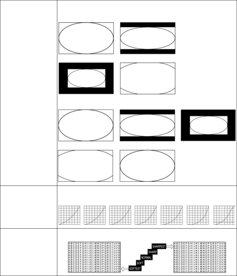
OSD POSITION Adjusts the position of the OSD
0: 1: 2:
3: 4: 5:
6: 7: 8:
27
OSD TIMEOUT Adjusts the time until the OSD Menu will disappear after adjusting the
menu.
ZOOM / PAN Controls the zoom in / out of the image.
RESET Reset the unit to factory outgoing status
AUTO SOURCE
SELECT When AUTO SOURCE SELECT is on, the monitor automatically
searches input source, except PIP sub source
USER NAME
ENTRY Put User’s name, etc. into Preset
WINDOW
LAYOUT Change sub window layout (SINGLE, PIP, PBP1, PBP2)
0: 1: 2:
3: 4: 5:
6: 7: 8:
Controls the PAN in / out of the image
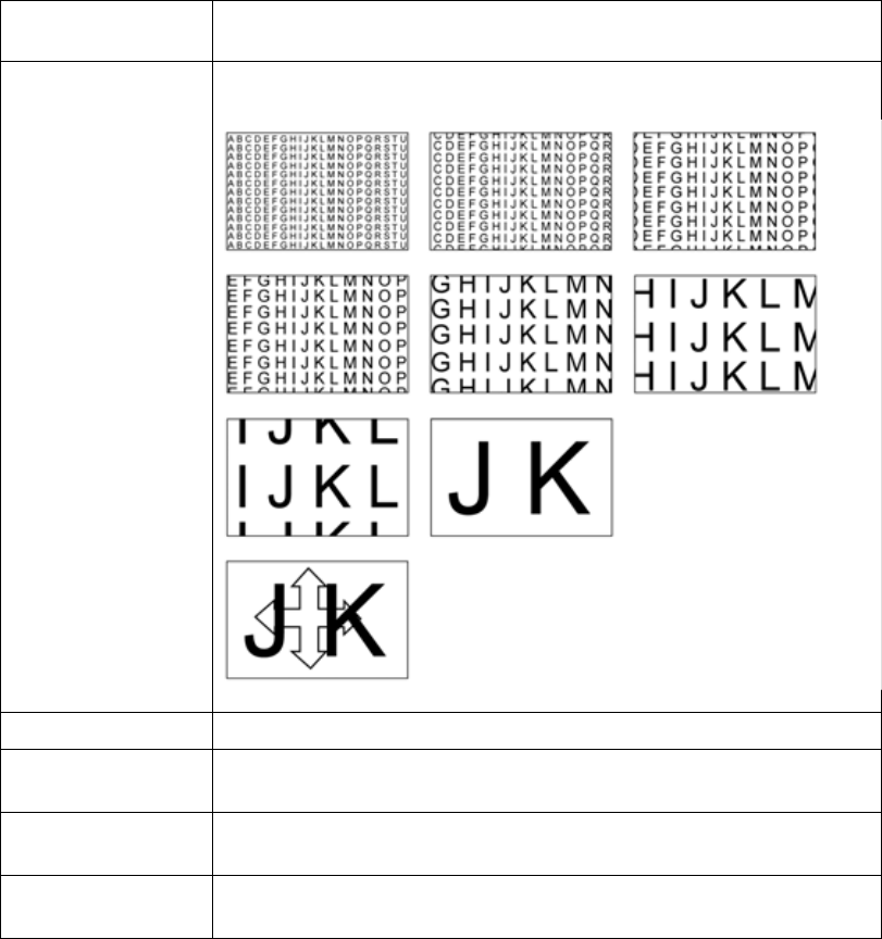
NOTICE: Maximum ZOOM size is ten times as large
as original size
28
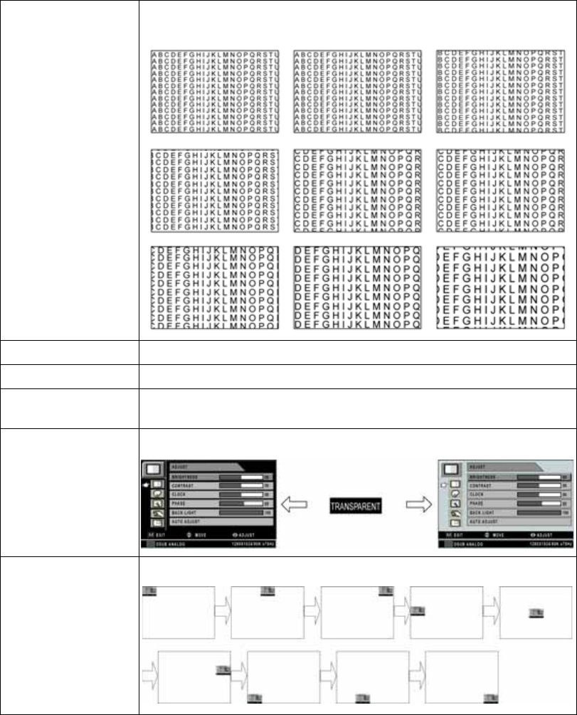
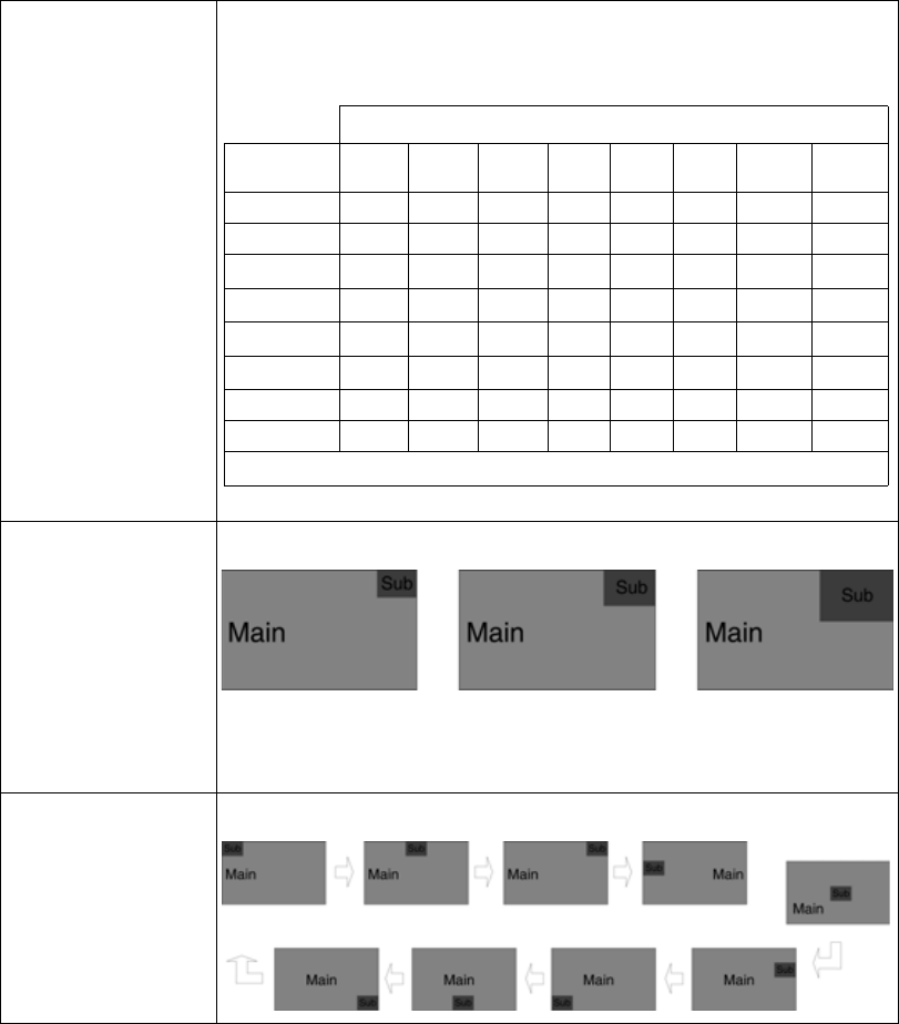
PIP SOURCE Select PIP source input. You can change other sub windows through OSD
PIP menu. The table below is a PIP matching table with main and sub
window.
PIP SIZE Change PIP mode sub window size
CAUTION: Do not change input Source aspect ratio. The PIP image size
is changeable depending on input timing.
PIP POSITION Change PIP mode sub window position
Sub Window
Input Source DVI
Optical DVI
Digital DSUB
Analog SDI YPbPr RGBS CVIDEO SVIDEO
DVI Optical X 0 0 0 0 0 0 0
DVI Digital 0 X X 0 X X 0 0
DSUB Analog 0 X X 01XX 0 0
SDI 0 0 01X0
101XX
YPbPr 0 X X 01XX 0 0
RGBS 0 X X 01XX 0 0
CVIDEO000X00X X
SVIDEO000X00X X
01: Support up to UXGA, 60Hz (162MHz)
25% / Panel Size 33% / Panel Size 50% / Panel Size
29
SWAP Change the main window and sub window position on PIP, PBP1, PBP2
PIP
PBP1
PBP2
Primary
PrimarySecondary
Secondary
30
1.11 Standard Signal Table
Resolution Horizontal
Frequency (KHz) Vertical Frequency
(Hz) Clock Frequency
(MHz)
640 x 350 @ 70 Hz 31.469 70.087 25.175
720 x 400 @ 70 Hz 31.469 70.082 28.324
640 x 480 @ 60 Hz 31.469 59.940 25.175
640 x 480 @ 75 Hz 37.500 75.000 31.500
800 x 600 @ 60 Hz 37.879 60.317 40.000
800 x 600 @ 75 Hz 46.875 75.000 49.500
1024 x 768 @ 60 Hz 48.363 60.004 65.000
1024 x 768 @ 75 Hz 60.023 75.029 78.750
1152 x 864 @ 60 Hz 54.348 60.053 80.000
1152 x 864 @ 75 Hz 67.500 75.000 108.000
1280 x 1024 @ 75 Hz 79.976 75.025 135.000
1360 x 768 @ 75 Hz 47.649 59.936 84.625
1600 x 1200 @ 60 Hz 74.077 59.981 130.375
1920 x 1080 @ 60 Hz 67.500 60.000 148.500
1920 x 1200 @ 60 Hz 74.099 59.999 154.125
31
1.12 SDI Video Format
1.13 VGA (15 Pin D-Sub)
Output Signal Description
SMPTE-274M 1080i (60 / 59.94 / 50)
1080p (30 / 29.97 / 25 / 24 / 24sF / 23.98 / 23.98sF)
SMPTE-296M 720p (60 / 59.94 / 50)
SMPTE-260M 1035i (60 / 59.94)
SMPTE-125M 480i (59.94)
ITU-R BT.656 576i (50)
Pin No. Assignment Pin No. Assignment
1 Red 8 Ground-Blue
2 Green 9 No Connection
3 Blue 10 Ground-Sync
4 Ground 11 Ground
5 DDC 5V Standby Cable
Connection Check 12 DDC Data
6 Ground-Red 13 H.Sync
7 Ground-Green 14 V.Sync
8 Ground-Blue 15 DDC Clock
15
106
11 15
32
1.14 DVI In, Out (24 DVI-D)
1.15 C-Video (BNC)
Pin No. Assignment Pin No. Assignment
1 T.M.D.S. Data 2- 13 No Connection
2 T.M.D.S. Data 2+ 14 +5V Power
3 T.M.D.S. Data 2 Shield 15 Cable Connection
Check
4 No Connection 16 Hot Plug Detect
5 No Connection 17 T.M.D.S. Data 0-
6 DDC Clock 18 T.M.D.S. Data 0+
7 DDC Data 19 T.M.D.S. Data 0
Shield
8 No Connection 20 No Connection
9 T.M.D.S. Data 1- 21 No Connection
10 T.M.D.S. Data 1+ 22 T.M.D.S. Clock
Shield
11 T.M.D.S. Data 1 Shield 23 T.M.D.S. Clock+
12 No Connection 24 T.M.D.S. Clock-
Pin No. Assignment
1 Composite
2 Ground
18
169
17 24
21
33
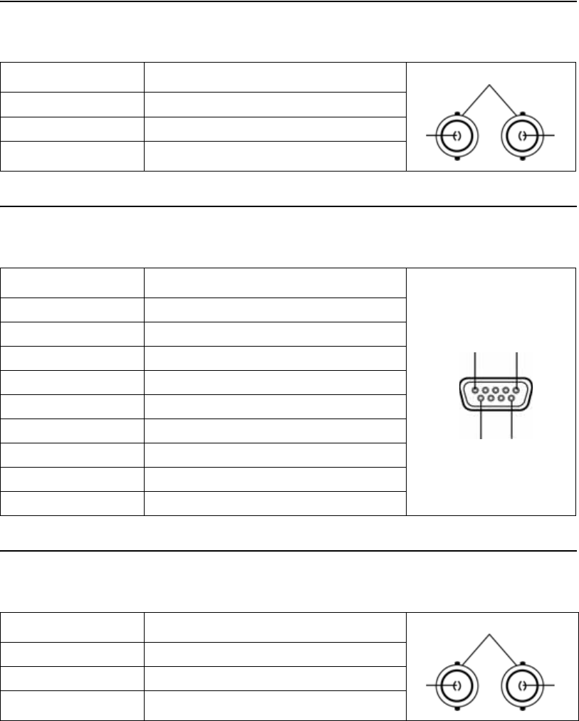
1.16 S-Video (BNC)
1.17 RS232C (D-SUB 9 Pin)
1.18 SDI (BNC)
Pin No. Assignment
1 S_VIDEO / Y (Luma)
2 S_VIDEO / C (Chroma)
3Ground
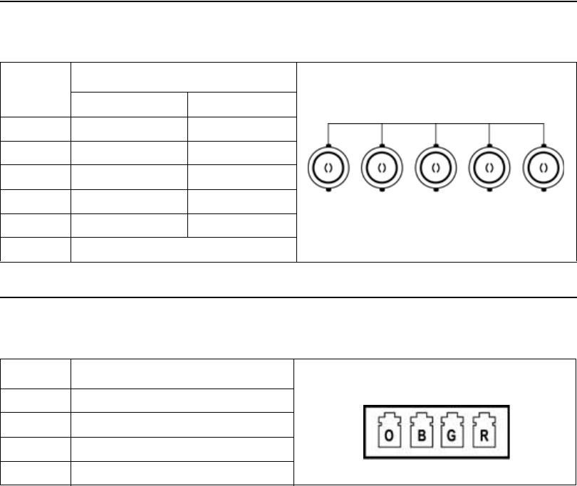
Pin No. Assignment
1 No Connection
2TXD
3RXD
4 No Connection
5 Ground
6 No Connection
7 No Connection
8 No Connection
9 No Connection
Pin No. Assignment
1SDI IN
2 SDI OUT
3 Ground
21
3
15
69
21
3
34
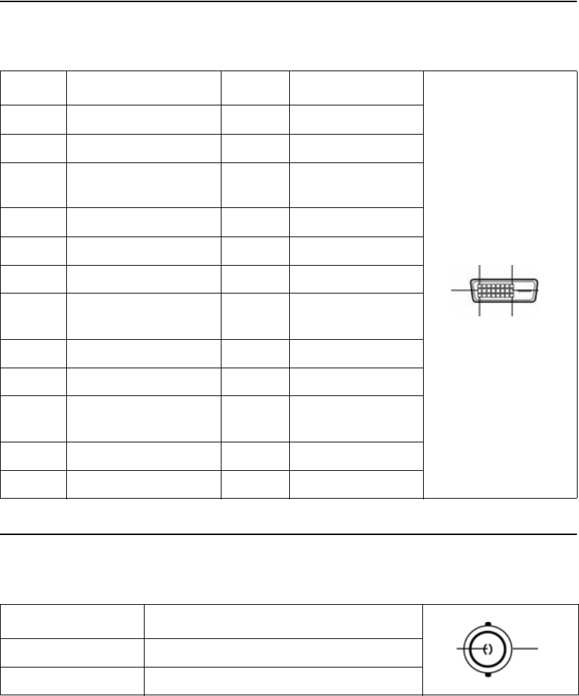
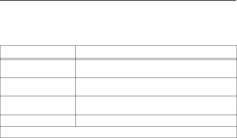
1.19 RGBHV / RGBS / YPbPr (BNC)
1.20 OPTICAL (available on VP4726F Monitor Only)
Pin No. Assignment
RGBS Y Pb Pr
1Red Pr
2 Green Y
3Blue Pb
4 H-Sync / C-Sync No Connection
5 V-Sync No Connection
6Ground
Pin No. Assignment
1 OPTICAL Clock
2OPTICAL Blue
3 OPTICAL Green
4OPTICAL Red
15324
6
R/Pr G/Y B/Pb C-SYNC/HS VS
1324

35
2.0 MAINTENANCE
Regular and proper maintenance of your
VP4726 and VP4726F Monitors is the best way
to protect your investment and avoid non-
warranty repairs.
Recommended care and handling of your
VP4726 and VP4726F Monitors includes proper
day-to-day operation and periodic inspection &
cleaning.
Your authorized ConMed Linvatec service
department is the most knowledgeable about the
ConMed Linvatec VP4726 and VP4726F
Monitors and will provide competent and
efficient service. Any services and/or repairs
done by any unauthorized repair facility may
result in reduced performance of the instruments
or instrument failure.
2.1 Life Expectancy
The standard warranty for this product is twelve
months. Life expectancy for the product is
expected to meet and exceed this period under
normal use and standard of care.
2.2 Periodic Maintenance
This product requires no periodic maintenance.
Occasional inspection of hardware interfaces is
recommended for high use connectors.
Periodically inspect for excessive wear or
damage to ensure effective data transfers.
Arrange for service if a connector is visibly
worn or damaged.
2.3 Cleaning Instructions
Follow universal precautions for protective
apparel when handling and cleaning
contaminated instruments.
1. Turn the monitor power off. Disconnect all
power cords and adaptors from the
electrical power source and from the rear of
the monitor.
2. Wipe monitor with a clean, soft cloth
dampened with a mild, pH- balanced
detergent.
3. Wipe again with distilled or sterilized
water.
4. Wipe dry with a clean, soft cloth.
36
2.4 Recommended Annual Monitor Maintenance Requirements
NOTE: Technical data is subject to modification, revision and improvement without notice.
Table 1: Recommended Annual Monitor Maintenance Requirements
Test Type Test Value
Ground Impedance ZG < 100 mOhm from the ground pin on the power inlet module
to the Console’s exposed metal parts. *
Test Chassis Leakage Currents IL < 100 uA in NORMAL Condition.
IL < 500 uA in Single Fault Conditions [300 uA US deviation] *
Test Earth Leakage Currents IL < 500 uA NORMAL Condition [300 uA US deviation]
IL < 1 mA Single Fault Condition *
Test Dielectric Withstand Test Line and Neutral to Ground @ V = 1500 V~, no breakdown *
* See IEC 60601-1 for test methods.
37
Table 2: Safety, Classifications
Classification of Equipment Parameter Value
According to protection against electric shock. Class I [Grounded]. this includes the AC/DC
Adapter (Bridgepower Corporation:
MW122RA2400F02)
According to degree of protection against
electric shock. Type B
According to degree of protection against
harmful ingress of water. IPX1
According to the degree of safety in the
presence of Flammable Anesthetics mixture
with air, with oxygen, or with nitrous oxide.
Equipment is NOT suitable for use in the presence
of flammable anesthetics mixture with oxygen or
with nitrous oxide.
According to the mode of operation. Continuous
UL Safety Compliance: This LCD monitor is U.L. Classified
with respect to electric shock, fire
and mechanical hazards only in
accordance with 60601-1/CAN/CSA
C22.2 NO. 601.1.
EEC Safety Compliance: This display meets the requirements
of EN-60601-1 so as to conform to
the Medical Device Directive 93/42/
EEC (general safety information).
NOTE: This monitor complies to the above standards only when used with the supplied
medical grade power supply, 24 Volt: Bridgepower Corporation: MW122RA2400F02.
The monitor should be powered from a center tapped circuit when used in the US at voltages
over 120 volts. Monitor is intended for continuous operation.
This display is energized from an external electrical power source for class 1 equipment. It is
the responsibility of the installer to test the display’s earth ground to verify that it complies
with the hospital, local and national impedance requirements.
38
2.5 Technical Specifications
VP4726 and VP4726F Monitors
LCD Panel
Type TFT-LCD
Screen Size 26 inch
Maximum Resolution 1920 x 1200 @ 60 Hz
Pixel Pitch 0.2865 mm (H) x 0.2865 mm (V)
Display Colors 16.7M
Contrast Ratio 1000:1
Viewing Angle 89° /89° /89° /89°
Response Time 12 msec (Rising + Falling)
Luminance 400cd/m2
Synchronization Horizontal Frequency 30KHz~75KHz
Vertical Frequency 50Hz~75Hz
Power Consumption Maximum Max 120W
Stand-by Mode Max 20W
Control Key Front Side ▲, ►, ▼, ◄, INPUT, PIP, MENU, POWER
Input Signal Video
1XDVI, 1XOptical DVI (VP4726F Monitor
Only), 1XD-SUB, 1XBNC (CVBS), 2XBNC
(SVHS Y/C), 1XBNC (SDI), 5XBNC
(Component Y/G, Pb/B, Pr/R, H/CS, VS
Input)
Input Signal Video 1XDVI, 1XBNC (SDI)
Input Power DC 24V, 6.25A Max
Weight 18.7 lbs. (8.5 kg)
Dimensions 24.6” (W) x 17.6” (H) x 4.1” (D)
625 mm (W) x 445.7 mm (H) x 103.4 mm (D)
IEC Equipment
Classification Class 1, Continuous Operation
39
NOTES:
1. If the product is connected to a 240V system in the United States, then it must be connected
to a center tap system.
2. The VP4726 and VP4726F Monitors contain electronic components and may
require special handling for end-of-life disposal. Refer, for example, to Directive
2002/96/EC (WEEE Guidelines) for disposal in the European Union or other local
guidelines regarding disposal of electronic components.
ENVIRONMENTAL
Operating Ambient Temperature: + 32° F to 104° F (+0° C to 40° C)
Relative Humidity: 30% to 75%, non-condensing
Atmospheric Pressure: 700 hPa to 1060 hPa
Transport and Storage Ambient Temperature: - 4° F to 140° F (-20° C to + 60° C)
Relative Humidity: 10% to 85%, non-condensing
Atmospheric Pressure: 500 hPa to 1060 hPa
40
Power Cord Requirements:
100/120 Volt (Cat. No. C7104)
Use only a listed (UL, CSA) detachable power cord manufactured to the following specifications.
• Plug End
• NEMA 5-15P hospital grade, 15 amps, 125V
• Receptacle End
• IEC 320/CEE-22, 6 amps, 250V/15 amps, 125V
• Cord
• UL style SJT, 14 AWG, 3 conductor
220/240 Volt (Cat. No. C7105)
• Plug End
• Molded straight PVC plug with double grounding system
• DIN 49441, CEE 7/U11, 10/16A, 250V
• CEBEC, DEMKO, KEMA, NEMKO, OVE, SEMKO, VDE, UTE, FEMKO
• Receptacle End
• Molded straight PVC plug
• DIN 49457, CEE 22/V, 10A, 250V
• VDE, D, N, S, SEV, OVE, KEMA
• Cord
• PVC, 7.2mm diameter
• 10A, 250V
• Conductors: 3 x 1 mm2
• Conductor Colors - brown, blue, green/yellow stripe

41
2.6 Detailed EMC Information
The equipment has been tested and found to
comply with the EMC limits for Medical Devices
per EN 55011 Class B and EN 60601-1-2. These
limits are designed to provide reasonable
protection against harmful interference in a
typical medical installation. Operation is subject
to the following two conditions: 1) this VP4726
Monitor may not cause harmful interference, and
(2) this VP4726 Monitor must accept any
interference received, including interference that
may cause undesired operation.
The Equipment generates and can radiate radio
frequency energy and, if not installed and used
in accordance with the instructions, may cause
harmful interference to other devices in the
vicinity. However, there is no guarantee that
interference will not occur in a particular
installation.
If this equipment does cause harmful interference
with other devices, which can be determined by
turning the equipment off and on, the user is
encouraged to try to correct the interference by
one or more of the following measures:
• Reorient or relocate the receiving device.
• Increase the separation between the
equipment.
• Connect the equipment to an outlet on a
circuit different from that to which the
other device(s) is connected.
• Consult the manufacturer or a field service
technician for assistance.
FCC WARNING :
This equipment generates or uses radio
frequency energy. Changes or modifications to
this equipment may cause harmful interference
unless the modifications are expressly approved
in the instruction manual. The user could lose
authority to operate this equipment if an
unauthorized change or modification is made.
NOTES:
1. The EMC tables and other guidelines
that are included in the Instruction
Manual provide information to the
customer or user that is essential in
determining the suitability of the
Equipment or System for the Electro-
magnetic Environment of use, and in
managing the Electromagnetic
Environment of use to permit the
Equipment or System to perform its
intended use without disturbing other
Equipment and Systems or non-medical
electrical equipment.
2. Medical Electrical Equipment needs
special precautions regarding EMC and
needs to be installed and put into service
according to the EMC information
provided in the Accompanying Documents.
42
WARNINGS:
1. Portable and mobile RF communications equipment can affect Medical Electrical
Equipment.
2. Use of accessories, transducers, and cables other than those specified, with the exception of
transducers and cables sold by the manufacturer of the equipment as replacement parts for
internal components, may result in increased emissions and decreased immunity of the
equipment or system.
3. The console should not be used adjacent to or stacked with other equipment, and that if
adjacent or stacked use is necessary, the equipment or system should be observed to verify
normal operation in the configuration in which it is intended to be used.
4. Under extreme conditions of primary power voltage sag [Primary voltage less than 60% of
mains] the device may require operator intervention to recover lost image. Device may have
to be restarted by pressing On/Standby Switch.
Table 3: Guidance and Manufacturer’s Declaration - Electromagnetic Immunity
The ConMed Linvatec VP4726 and VP4726F Monitors are intended for use in the electromagnetic
environment specified below. The customer or the user of the VP4726 and VP4726F Monitors
should assure it is used in such an environment.
Emissions Test Compliance Electromagnetic environment - guidance
RF Emissions
CISPR 11 Group 1 The VP4726 and VP4726F Monitors use RF energy
only for its internal function. Therefore, its RF
emissions are very low and are not likely to cause
any interference in nearby electronic equipment.
RF Emissions
CISPR 11
Class B
The VP4726 and VP4726F Monitors are suitable for
use in all establishments, including domestic
establishments and those directly connected to the
public low-voltage power supply network that
supplies buildings used for domestic purposes.
Harmonic Emissions
IEC 61000-3-2
Class D
Voltage fluctuations
/ flicker emissions
IEC 61000-3-3
Complies

43
Table 4: Guidance and Manufacturer’s Declaration - Electromagnetic Immunity
The ConMed Linvatec VP4726 and VP4726F Monitors are intended for use in the electromagnetic
environment specified below. The customer or the user of this VP4726 and VP4726F Monitors
should assure that it is used in such an environment.
Immunity Test IEC 60601
Test Level Compliance Level Electromagnetic environment
guidance
Electrostatic
discharge (ESD)
IEC 61000-4-2
± 6 kV contact
± 8 kV air
± 6 kV contact
± 8 kV air
Floors should be wood, concrete or
ceramic tile. If floors are covered
with synthetic material, the relative
humidity should be at least 30%.
Electrical fast
transients / bursts
IEC 61000-4-4
± 2 kV for power
supply lines
± 1 kV for input/
output lines
± 2 kV for power
supply lines
± 1 kV for input/
output lines
Mains power quality should be that
of a typical commercial or hospital
environment.
Surge
IEC 61000-4-5
± 1 kV line to line
± 2 kV lines to earth
± 1 kV line to line
± 2 kV lines to earth
Mains power quality should be that
of a typical commercial or hospital
environment.
Power frequency
(50/60 Hz)
magnetic field
IEC 61000-4-8
3 A/m 3 A/m Power frequency magnetic fields
should be at levels characteristic of
a typical location in a typical
commercial or hospital
environment.
Voltage dips, short
interruptions and
voltage variations
on power supply
input lines
IEC 61000-4-11
<5% Ut
(>95% dip in Ut)
for 0.5 cycle
40% Ut
(60% dip in Ut)
for 5 cycles
70% Ut
(30% dip in Ut)
for 25 cycles
<5% Ut
(>95% dip in Ut)
for 5 seconds
<5% Ut
(>95% dip in Ut)
for 0.5 cycle
40% Ut
(60% dip in Ut)
for 5 cycles
70% Ut
(30% dip in Ut)
for 25 cycles
<5% Ut
(>95% dip in Ut)
for 5 seconds
Mains power quality should be that
of a typical commercial or hospital
environment. If the user of the
VP4726 and VP4726F Monitors
requires continued operation
during power mains interruptions,
it is recommended that theVP4726
and VP4726F Monitors be powered
from an uninterruptable power
supply or battery.
Note: Ut is the a.c. mains voltage prior to application of the test level.
44
Portable and mobile RF
communications equipment should
be no closer to any part of the
VP4726 and VP4726F Monitors,
including cables, than the
recommended separation distance
calculated from the equation
applicable to the frequency of the
transmitter.
Recommended Separation
Distance
Conducted RF
IEC 61000-4-6
3 Vrms
150 kHz to 80 MHz
3 Vrms
150 kHz to 80 MHz d = [3.5 / V1] √ P
Table 4: Guidance and Manufacturer’s Declaration - Electromagnetic Immunity
The ConMed Linvatec VP4726 and VP4726F Monitors are intended for use in the electromagnetic
environment specified below. The customer or the user of this VP4726 and VP4726F Monitors
should assure that it is used in such an environment.
Immunity Test IEC 60601
Test Level Compliance Level Electromagnetic environment
guidance
45
Radiated RF
IEC 61000-4-3
3 V/m
80 MHz to 2.5 GHz
3 V/m
80 MHz to 2.5 GHz d = [3.5 / E1] √ P
80 MHz to 800 MHz
d = [7 / E1] √ P
800 MHz to 2.5 GHz
Where P is the maximum output
power rating of the transmitter in
watts (W) according to the
transmitter manufacturer and d is
the recommended separation
distance in meters (m).
Field strengths from fixed RF
transmitters, as determined by an
electromagnetic site survey a,
should be less than the compliance
level in each frequency range b.
Interference may occur in the
vicinity of equipment marked with
the following symbol.
Note 1: At 80 MHz and 800 MHz, the higher frequency range applies.
Note 2: These guidelines may not apply in all situations. Electromagnetic propagation is affected
by absorption and reflection from structures, objects, and/or people.
aField strengths from fixed transmitters, such as base stations for radio (cellular / cordless) telephones and land
mobile radios, amateur radio, AM and FM radio broadcast and TV broadcast cannot be predicted theoretically
with accuracy. To assess the electromagnetic environment due to fixed RF transmitters, an electromagnetic
site survey should be considered. If the measured field strength in the location in which the VP4726 and
VP4726F Monitors are used exceeds the applicable RF compliance level above, the VP4726 and VP4726F
Monitors should be observed to verify normal operation. If abnormal performance is observed, additional
measures may be necessary, such as re-orienting or relocating the VP4726 and VP4726F Monitors.
b Over the frequency range 150 kHz to 80 MHz, field strengths should be less than 3 V/m.
Table 4: Guidance and Manufacturer’s Declaration - Electromagnetic Immunity
The ConMed Linvatec VP4726 and VP4726F Monitors are intended for use in the electromagnetic
environment specified below. The customer or the user of this VP4726 and VP4726F Monitors
should assure that it is used in such an environment.
Immunity Test IEC 60601
Test Level Compliance Level Electromagnetic environment
guidance
46
Table 5: Recommended Separation Distances Between Portable and Mobile RF
Communications Equipment and the VP4726 and VP4726F Monitors
The ConMed Linvatec VP4726 and VP4726F Monitors are intended for use in an electromagnetic
environment in which radiated RF disturbances are controlled. The customer or the user of the
VP4726 and VP4726F Monitors can help prevent electromagnetic interference by maintaining a
minimum distance between portable and mobile RF communications equipment (transmitters) and
the VP4726 and VP4726F Monitors as recommended below, according to the maximum output
power of the communications equipment.
Separation Distance According to Frequency of Transmitter
m
Read Maximum
Output Power
of Transmitter
150 kHz to 80 MHz 80 MHz to 800 MHz 800 MHz to 2.5 GHz
Wd = [3.5/V1] √ P
V1 = 3V/m
d = [3.5/E1] √ P
E1 = 3V/m
d = [7/E1] √ P
E1 = 3V/m
0.01 0.12 0.12 0.23
0.1 0.37 0.37 0.74
1 1.17 1.14 2.33
10 3.70 3.70 7.37
100 11.70 11.70 23.3
For transmitters rated at a maximum output power not listed above, the recommended separation
distances d in meters (m) can be estimated using the equation applicable to the frequency of the
transmitter, where P is the maximum output power rating of the transmitter in watts (W) according
to the transmitter manufacturer.
Note 1: E1) At 80 MHz and 800 MHz, the separation distance for the higher frequency range
applies.
Note 2: E2) These guidelines may not apply in all situations. Electromagnetic propagation is
affected by absorption and reflection from structures, objects, and people.
47
2.7 Obtaining Parts and Accessories
When obtaining parts or accessories, please supply the following information:
1. Instrument Model / Serial number
2. Component description
3. Quantity desired
4. ConMed Linvatec Part / Catalog number
5. Component reference designator (if applicable)
Accessory Description Part Number
DVI-D Cables
DVI-D Video Cable, DVI to DVI, 3 ft. IM9020
DVI-D Video Cable, DVI to DVI, 6 ft. IM9021
DVI-D Video Cable, DVI to DVI, 10 ft. IM9003
DVI-D Video Cable, DVI to DVI, 25 ft. IM9022
Power Cables
Power Cord, 115 V, 1 ft. C7104-1
Power Cord, 115 V, 2 ft. C7104-2
Power Cord, 115 V, 3 ft. C7104-3
Power Cord, 115 V, 4 ft. C7104-4
Power Cord, 115 V, 6 ft. C7104
Power Cord, 230 V, 10 ft. C7105

48
2.8 Customer Service
2.8.1 Assistance
If you need technical assistance regarding the
use or application of this product, or you
encounter a problem that requires servicing or
repair, contact ConMed Linvatec Customer
Service at 800-925-4255 or your ConMed
Linvatec Sales Representative. Outside the U.S.
contact your local ConMed Linvatec
Representative.
Report any events involving injuries or
malfunctions to the ConMed Linvatec
Regulatory Product Support.
2.8.2 Repairs
Products returned for any reason must have an
authorized Return Goods (R.G.) number
prominently displayed on the box and included
on all paperwork. Refer to this number if
making inquiries about repair status. Please call
ConMed Linvatec Customer Service and
provide the following information to obtain an
R.G. number prior to returning any product for
repair:
• Product Number
• Serial/Lot Number - if applicable
• Original Invoice Number
• Date of Purchase
• Detailed description of the problem
All returns should be sent to:
ConMed Linvatec
Attn.: Customer Service Dept.
7416 Hollister Avenue
Santa Barbara, CA 93117 USA
Customer Service
(within U.S.) Phone: 800-925-4255
FAX: 727-399-5256
(outside U.S.) Phone: 727-392-6464
FAX: 727-397-4540
ConMed Linvatec Regulatory Product Support
(within U.S.) Phone: 800-237-0169
(outside U.S.) Phone: 727-392-6464

All rights reserved. Printed in USA W41-147-004 Rev. AA 11/2008
ConMed Linvatec BioMaterials, Ltd.
Hermiankatu 6-8L
33720 Tampere, FINLAND
EC REP