DANBY Air Conditioner Room (42) Manual L0712245
User Manual: DANBY DANBY Air Conditioner Room (42) Manual DANBY Air Conditioner Room (42) Owner's Manual, DANBY Air Conditioner Room (42) installation guides
Open the PDF directly: View PDF ![]() .
.
Page Count: 30
USE ANDCARE
MANUAL
MANUEL
D'UTILISATION
Model,ModUle
DAC7024DE
ReadandFollov/AllSafetyRutes
andOperalinginstructionsBefore
F]rstUseof ThisProduct.
Ve_ElezI_e attenlivement
loseonsignesd_s_curit_et los
Instructionsd'ulflls&lionevent
I'u=Jlisattonlnltialede
ce produit.
f
,, ,_ . .
, ,,,,,,,, _,_, __
_ _ _ _ ..................
_It_ 1 _ _ ...... _ I_Ill Ill _ II I_2_2
,:......................;_
I,_ _® ®;
Room Air Conditioner
Table of contents ....................... 1
Climatiseur de piGce
Table of contents 15
DanbyP|'oductsLimited,Guelph,OntarioCanadaN1H6Z9
DanbyP_'oduclstnc,,Findlay,OhioUSA 45840
lO,Ol.
Page
Introduction .................................................................. 2
Unit Specifications ............................................................. 2
Electrical Specifications .......................................................... 3
Energy-Saving T_ps........................................................... 4
Window Installation ............................................................ 4
Operating Instructions .......................................................... 11
Care and Maintenance ............................................................. 12
Trouble Shooting Guide ....................................................... 13
Warranty ................................................................... 14
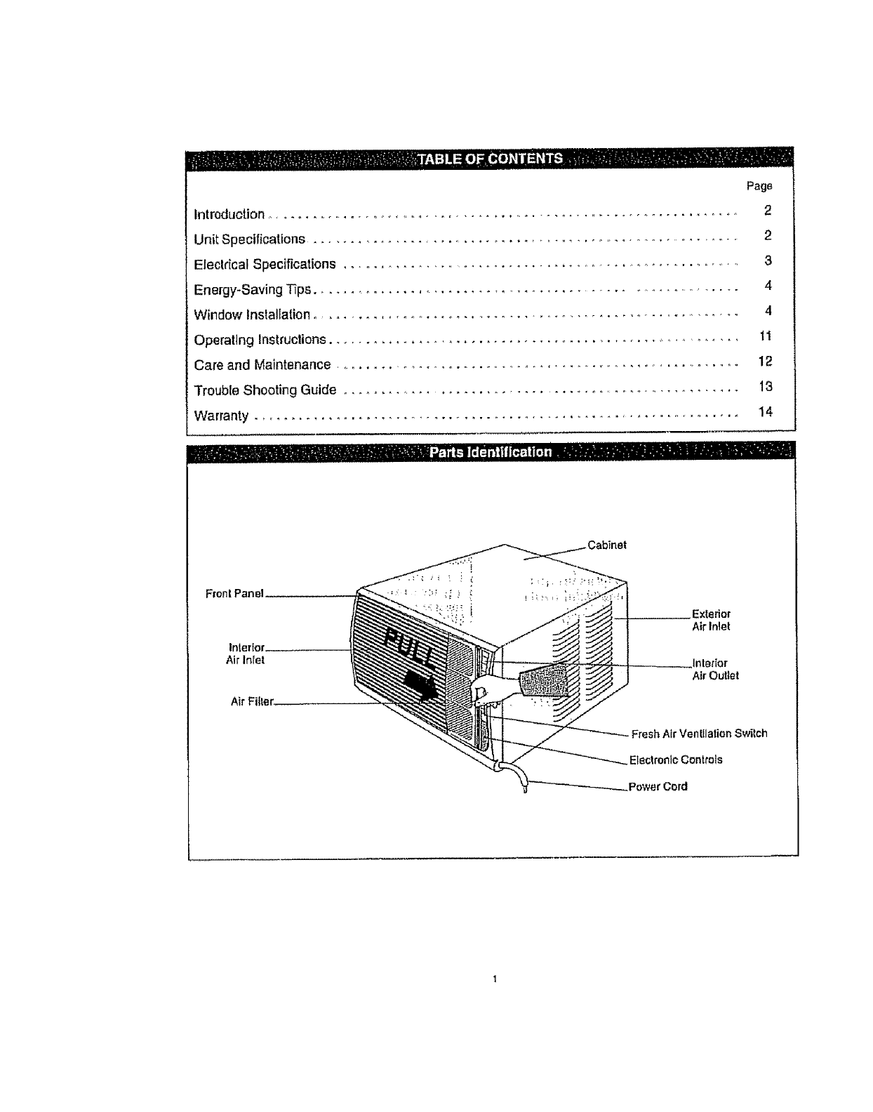
tnierior__
Air Inlet
Air Filler
Exterior
Air Inlet
Interior
Air Outlet
-Fresh Air Ventilation Switch
Electronic Controls
Power Cord
u_i .... .=_ I '11111 ,i I ' '1'1 ' i
-- - l#iiI{_t_li[oii[,l_ - -
Thank you for choosing a Danby Silhouette RoomAir Conditioner to cool your home. This Use and Care
Manual provides information necessary for the proper care and maintenance of your new Room Air
Condittoner_ If propedy maintained, your air conditioner will give you many years of trouble free operation. To
avoid insfallation dilficulties, i'ead Ihese inslruclions completely before installing!operating your untL
NOTE,' This unit is NOT designed for through-the-walt installation,
For easy reference, you may want to attach a copy of your sales receipt to this page. Note following
information provided (on the marlulacturer's nameplafe located on the right side of the unil above 1,5epower
cord) This information wil! be needed when you contact a Customer Service Representative
Model Number:
Serial Number:
Date of Purchase:
Dealer s Name and Address:
Refer to the trouble shooting section o! this Use end Care Manual if Ihe unil is not operaling correctly.
tf these suggeslions do net solve the problem, conlact an authorized service representative or
call Danby TOLL F.REE: 1-800-263-2629
Keep these instructions for future reterence.
This symbol denotes acaution or warning
Do not leave a room air condtlioner unattended in
a space where people or animals who cannot
react Io a failed unit are located, A failed unit can
cause exfreme overheating or death in such an
enclosed, unattended space.
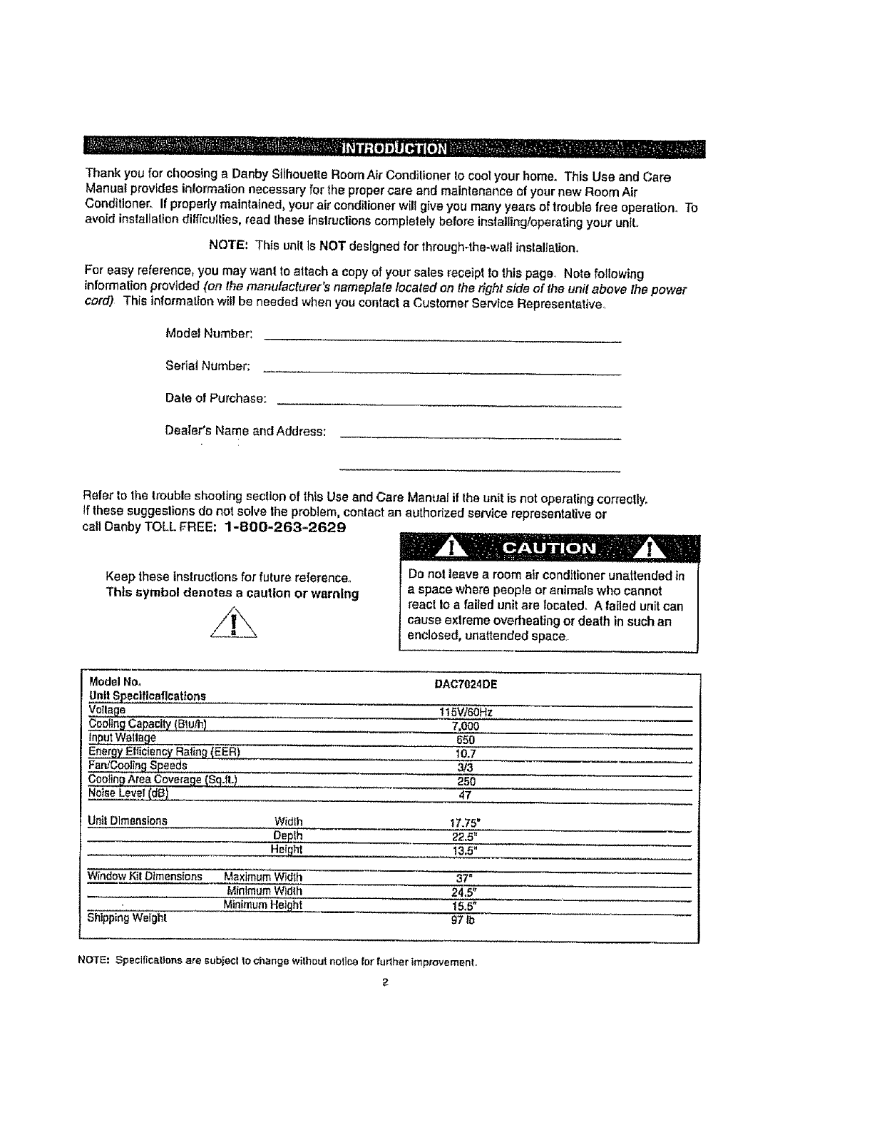
ModelNo, DAC7024DE
Lintl Spec!lieatleat!ons
Vet!age It 5V/60Hz
CoolingCapacitY(Btu_) 7,000
65o
Energy EfficiencyRatin_(EER) 10.7
Fen,<CoolingSpeeds 3/3
_Sq_f=.) 250
NoiseLevel(dB) 47
Unl! Dimensions Width 17.75"
Depth 22.5"
Heig._ 13.5"
Wfndow Kil Dtmens{ons Maximum Width 37"
Minimum Widlh 24.5"
Minimu_ 15,5"
Shtpping Welghl 97 ib
NOTE: $pecllic_itlene are subjecl 1ochange will_ou!noltce let further irnprovernerll,
2
1o All wiring must comply with local and national
electrical codes and must be installed by a
qualified electrician. Ifyou have any questions
regarding the fo)(owIng instructions, contact a
qualified electric(an.
2. Check available power supply and resolve any
w(ring problems BEFORE installing and
operating this unit°
3. Th(s 1t5V air condilioner uses 12.0 or less
nameplate amps and may be used in any
properly wired, general purpose household
receptacle. See Table 1for specifications for
individual branch circuit.
4. For your safety and protection, this unit ts
grounded through the power cord plug when
plugged into into a matching wall eutteL If
you are not sure whether your wall outlet Is
properly groun.ded, please cons u!t a
qu_i fled electrlc.lan, :,. ""
T,g: iiouiieii3-p iimate,thep,ug(3-
pin)on theservicecordsuppliedwiththeunit.
DO NOT use plugadapters,See Table2 for
receptacle and fuse information. If tt Is necessary
to use an extension cord to connect your air
conditioner, use an approved "air conditioner"
extension cord only (available at most local
hardware stores)
6. The ratingplate on the unit contains electrical
and other technical data, The raling plate
is located on the right stde of the unit, above the
power cord.
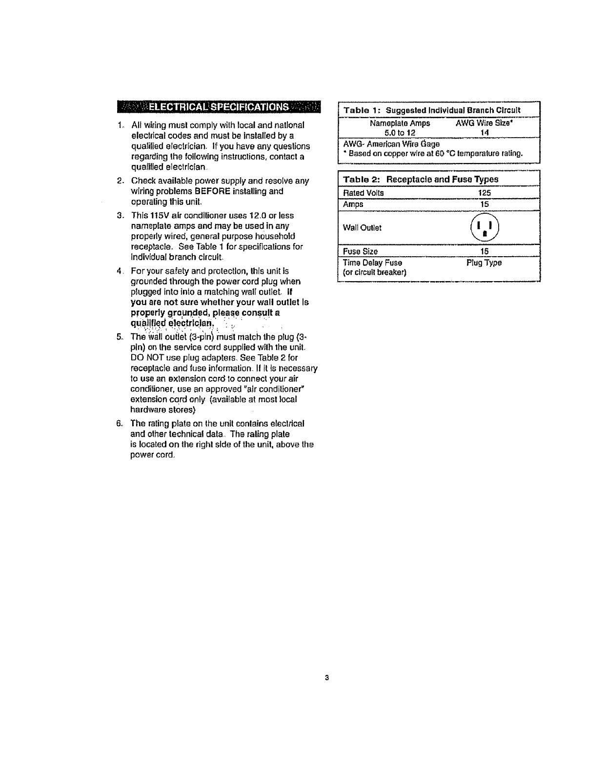
Table 1: Suggested Individual Branch Circuit
NameplateAmps AWG Wi_eSize"
5,0 to 12 14
AWG- AmericanWi_e_age
*Based en copperwireat 60 _Ctemperaturerating.
Table 2: Receptacle and Fuse Types
RatedVolts 125
Amps 15
Wail Oultet
Fuse Size t5
Time Delay Fuse PlugType
(or clrcutl breaker)
YourRoomAirCondillonerunitisdesignedto
be highly efficient in energy savlngs_ Follow
these recommer_dations Ior greater eltidenoy_
1 Select thermostal selling Ihal suits your
comiod needs and reave lherrnosla! at that
chosen selling.
2_ The air filler is very elfJdenl in removing airborne
dust padicleso Always keep the air filter clean.
3_ Use drapes, curtains, or shades to keep
direct sunlight from hsating room, but DO NOT
obstruct the air conditioner. Allow air to circulate
around t,he unit without obstruction.
4_ Start your air conditioner bolero outdoor air
becomes hot and uncomfodable, This avoids an
initial period of discomfod while unit is cooling
off the room,
5- When ouldoor temperatures are coo! enough,
use HIGH, MED, or LOW FAN only (depending
on your model). This circulates indoor air,
providing some cooling comlod, and ulilizes
less electricity than when operating on a
cooling setting.
_ To avoid (he possibi;ityof personal
injury, disconnect power to the unit
before installing or servicing..
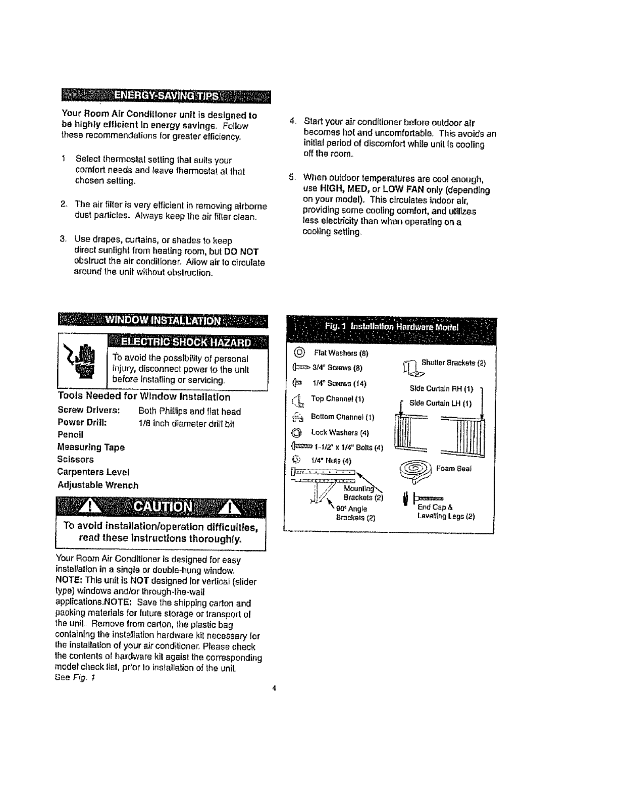
Tools Needed for Wtndow Installation
Screw Drivers: Both Phillips and flat head
Power DrIIl: 1/8 inch dtameler drill bit
Pencil
Measuring Tape
Scissors
Carpenters Level
Adjustable Wrench
To avoid installation/operation difficulties,
read these Instructions thoroughlyo
Your Room Air Conditioner is designed for easy
installation in a single or double-hung v,_ndow.
NOTE: This unit is NOT designed for vertical (slider
type) windows and/or through-the-wall
applicationsoNOTE: Save the shipping carton and
packing maleriars for lulure slorage or transport ol
_,haunit Remove from or!!on, the plastic bag
containing the insta!latton hardware kit necessary for
Ihe installation of your air conditioner, Please check
Ihe contents of hardware kit age!st the corresponding
model cl_ack Ifst, prior to installationof the unit
S_e Fig. I
Because the compressor is located on the conbols
side of the unit (righl side), this side wilt be heavlel:
and more awkward to manipulate, Inadequate
support on control side of the unit can result in
personal injury and damage to your unit and
property. Therefore, it is recommended to have
someone assist you during the installation of this
untt
Your unit Is designed to evaporate condensation
under normal conditions However, under
extreme humidity conditions, excess condensation
may cause basepan to overflow to the outside.
The Unit should be installed where condensation
run-off cannot drip on pedestrians or neighboring
properties.
A drain tube connection (excluding hose) is provided
to redirect c_ndensation ovedtow Sea Fig, 25.
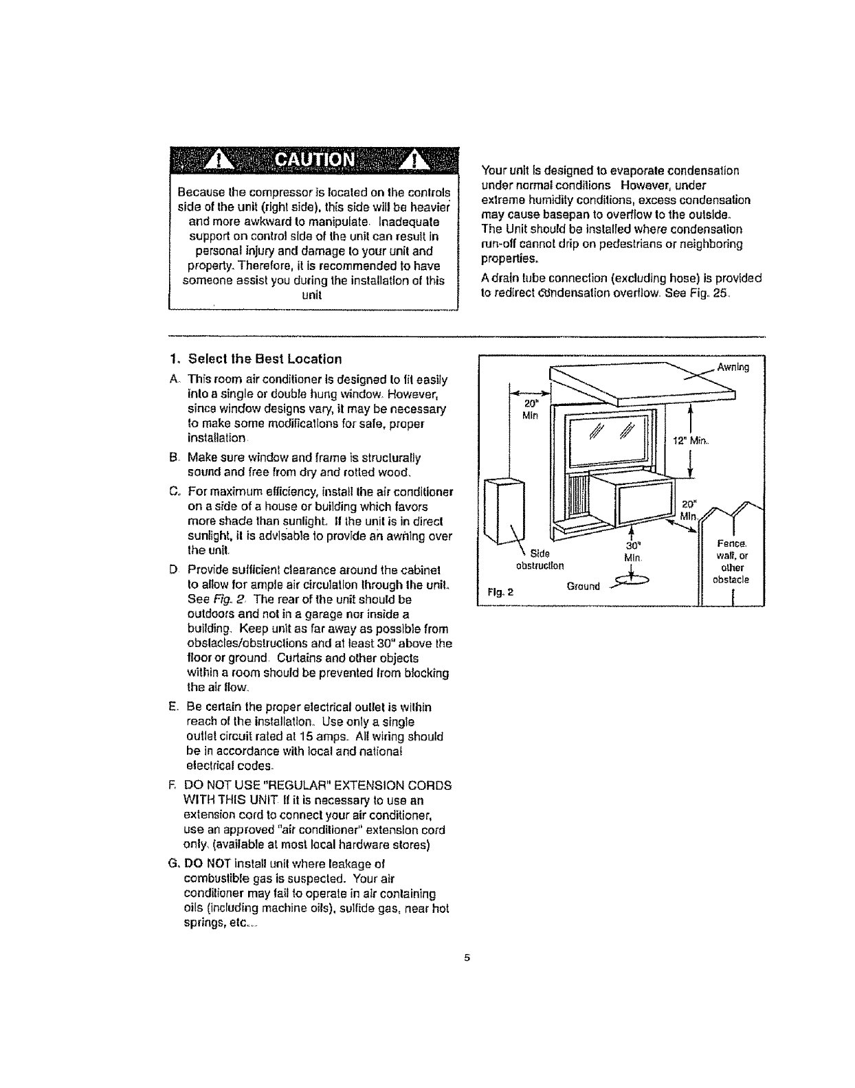
1. Select the Best Location
A. Thfs room air conditioner is designed to lit easity
into a single or double hung window_ However,
since window designs vary, it may be necessary
to make some modifications for safe, proper
installation
B, Make sure window and frame is structurally
sound and free from dry and retted wood,
Co For maximum efficiency, install Ihe air conditioner
on a side of a house er building which favors
more shade than §uniighto II the unit is in direct
sunlight, il is advisable to provide an awillng over
the unit.
D Provide sufficient clearance around the cabinet
to altow for ample air circulation through the unit.,
See Fig. 2 The rear ot' the unit should be
outdoors and not in a garage nor inside a
building. Keep unit as far away as possible from
obslacles/obstructions and at least 30" above the
floor or ground. Curtains and other objects
within a room should be prevented from blocking
the air flow,.
E. Be certain the proper electrical outlet is wilhin
reach of the installation° Use only a single
outlet circuit rated at 15 amps.. Al! wiring should
be in accordance with local and national
electrical codes.
EDO NOT USE "REGULAR" EXTENSION CORDS
WITH THIS UNIT If it is necessary to use an
extension cord to connect your air conditioner,
use an approved "air conditioner" extension cord
only, (available at most local hardware stores)
Go DO NOT Insla]l unit where leakage of
combuslible gas is suspected. Your air
condilioner may fait to operate in air containing
oils (including machine oils), sulfide gas, near hot
springs, elc......
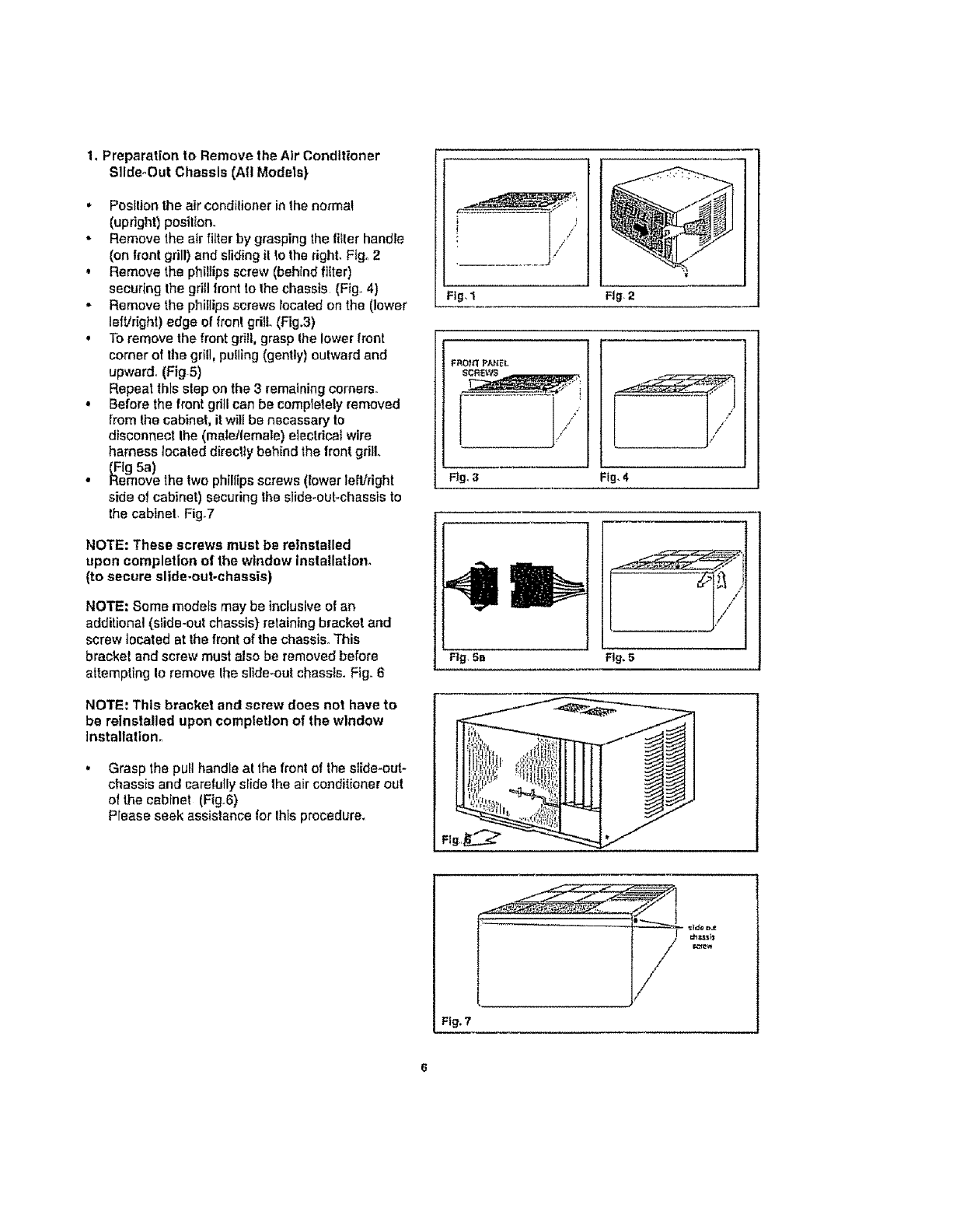
1,Preparation to Remove the Air Conditioner
SIIde_Out Chassis (Aft Models)
• Position the air condilioner in the normal
(upright) posil_on.
-Remove the air fitter by grasping the tiIler handle
(on front grill) and sliding il lo the right, Ftgo2
• Remove the phillips screw (behind fitter)
securing the grill Iront to the chassis (Fig. 4)
-Remove the phillips screws located on the (lower
lefVright) edge ei front grill (Flg.3)
•To remove the front gr_!l,grasp ihe lower front
comer of lhe grill, pulling (gently) outward and
upward, (Fig 5)
Repeat lhts slop on the 3 remaining corners,.
•Before the front grill can be completely removed
from the cabinet, it will be necassary to
disconnect Ihe (msletlemate) electricaf wire
harness located direclly behind the lront grill.
(Fig 5a)
•Remove the two phillips screws (lower left!right
side of cabinet) securing the slide-oul_chassls to
the cabinet, Figo7
NOTE: These screws must be reinstalled
upon completion of the window Installation°
(to secure slide-out-chassls)
NOTE: Some modets may be inclusive of an
additional (sfide-out chassis) retaining bracket and
screw located at the front of the chassis. This
bracket and screw must also be removed before
attempting Io remove Ihe slide-out chassis. Fig° 6
NOTE: This bracket and screw does not have to
be reinstalled upon completion of the window
Installation_
Grasp the pull handle at the front of the slide-out-
chassis and carefully slide the air conditioner out
of the cabinet (Fig.6)
Please seek assistance tor Ihis procedure_
i.............. l"
Fig,1
FRO_ P_EL
Rgo 3
!f/'J
Fig.4
Ftg_5-
///
Fig.5.
J
Ft
Fig. 7
/j
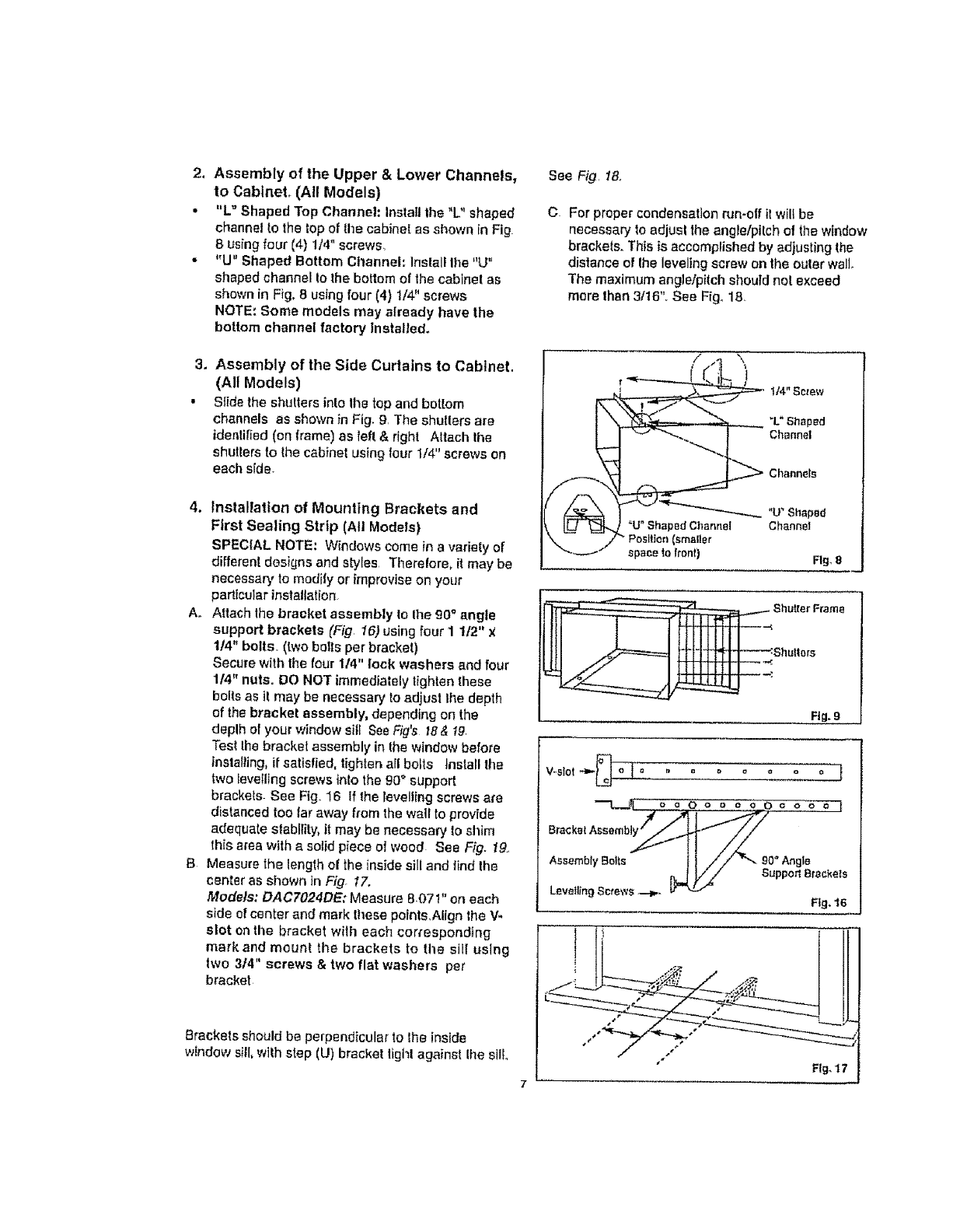
2, Assembly of the Upper &Lower Channels,
to Cabinet. (All Models)
• "L"Shaped Top Channel: Installthe "L"shaped
channel to the top of tile cabinet as shown [n Fig.
8using four (4) 114" screws.
•"U" Shaped Bottom CItannel: Install Ihe "U"
shaped channel io the bottom of the cabinel as
shown in Fig. B using four (4) 1/4" screws
NOTE: Some models may already have the
bottom channel factory Installed.
3, Assembly of the Side Curtains to Cabinet.
(All Models)
•Slide the shutters inlo Ihe top and bottom
channels as shown in Fig. 9. The shutters are
idenlilled (on frame) as taft & right Attach Ihe
shutlers to Ihe cabinet using four 1/4" screws on
each side.
4, Installation of Mounting Brackets and
First Sealing Strtp (All Models)
SPECIAL NOTE: Windows come in avariety of
different designs and styles Theralore, {t may be
necessary to modify or improvise on your
particular inelallation.
A. Attach the bracket assembly to Ihe 90° angle
support brackets (Fig 16) using four 11/2" x
1/4" bolts. (two bolts per brackel)
Secure with the four 1/4" lock washers and four
1/4" nuts. DO NOT immediately tighten these
bolts as it may be necessary to adjust lhe depth
of the bracket assembly, dependin£ on the
deplh of your window sill See Fig's t8 & 19
Test the brackel assembly in lhe window before
installing, if satisfied, tighlen all bolts lnslall the
two levelling screws into the 90 ° support
brackets See Fig. 16 li the levelling screws a_e
distanced too (ar away from the waTIto provide
adequate stability, it may be necessary to shim
this area with a solid piece oI wood See Fig. !9.
B Measure the length of the inside sill and find the
center as shown In Fig. 17.
Models; DACFO24DE: Measure 807 !" on each
side of center and mark Ihese points.Align the V-
slot on the bracket with each corresponding
markand mount the brackets to tile sil[ using
two 314" screws & tWO flat washers pe_
bracket
Brackets should be perpendicular to the inside
window sill, with step (U) bracket lighl against Ihe sill
See Fig, f8.,
C. For proper condensation run-off it wil_be
necessary to adjusl the angle/pitch ot the window
brackets. This is accomplished by adjusting the
distance of Ihe leveling screw on the ouler wall,
The maximum anglelpitch should nol exceed
more than 3/16", See Ffg_ 18
/ /t \
t/4" Semw
'L" Shaped
Channel
Channels
"U"Shaped
"U" ShapedChannel Channel
Position (smaller
spacetoIrenl) Fig.8
Shut.terFrame
Shu!lers
Fig. 9
As_embr_ao1_e t I //"" __°°An01_
. II.// _uppotl Brackets
Levelling Screws --.-_.
Fig, 16
I H
L
Fig,17
I
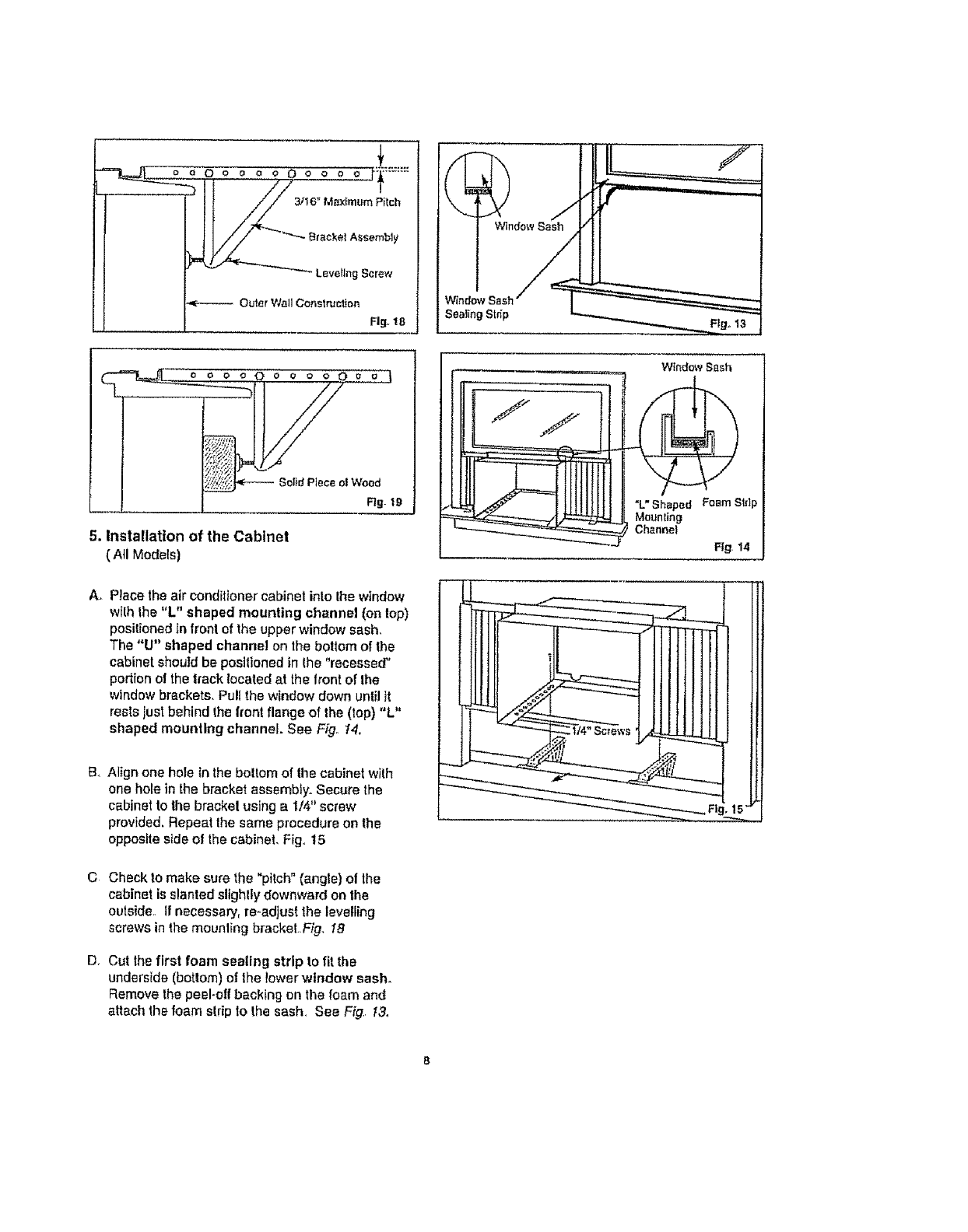
oo0 0 0 0 o 0 0 0 0 0 _*_:::::*'::
!
3/16"M m_ImornPitch
Braokel Assembly
Leveling Scrm',"
Outer Wall Construction
Fig. 18
WindowSash
0o o o o 0 E2 j
I_ SolidPtecec,IWood
...... .L Rg- I9
5. Installation of the Cabinet
(All Models)
A. Place the air conditioner cabinel into Iha window
with the "L" shaped mounting channel (on lop)
positioned tn front of the upper window sash,
The "U" shaped channel on the botlem of the
cabinet should be positioned in the "recessed"
portion of the track located at the front of the
window brackets, Pull the window down unlil it
rests just behind the front flange of the (top) "L"
shaped mounting channel. See Fig. !4,
WindowSnsh
"L'Shaped FoamSIdp
Mounling
Channel
Fig 14
B. Align one hole Inthe boltom of the cabinet with
one hole in the bracket assembly. Secure the
cabinet to the bracket using a 1/4" screw
provided. Repeat the same procedure on the
opposite side of the cabinet. Fig,,t5
C Check to make sure the "pitch" (angle) of the
cabinet is slanted slighlly downward on the
outside, If necessary, re-adjust the levelling
screws in the mounling brackeLFig. 18
D, Cut thefirst foam sealing strip to fit the
underside (bottom) of lhe lower window sash.
Remove the peel-off backing on the foam and
attach the foam strip to the sash, See Fig, t3_
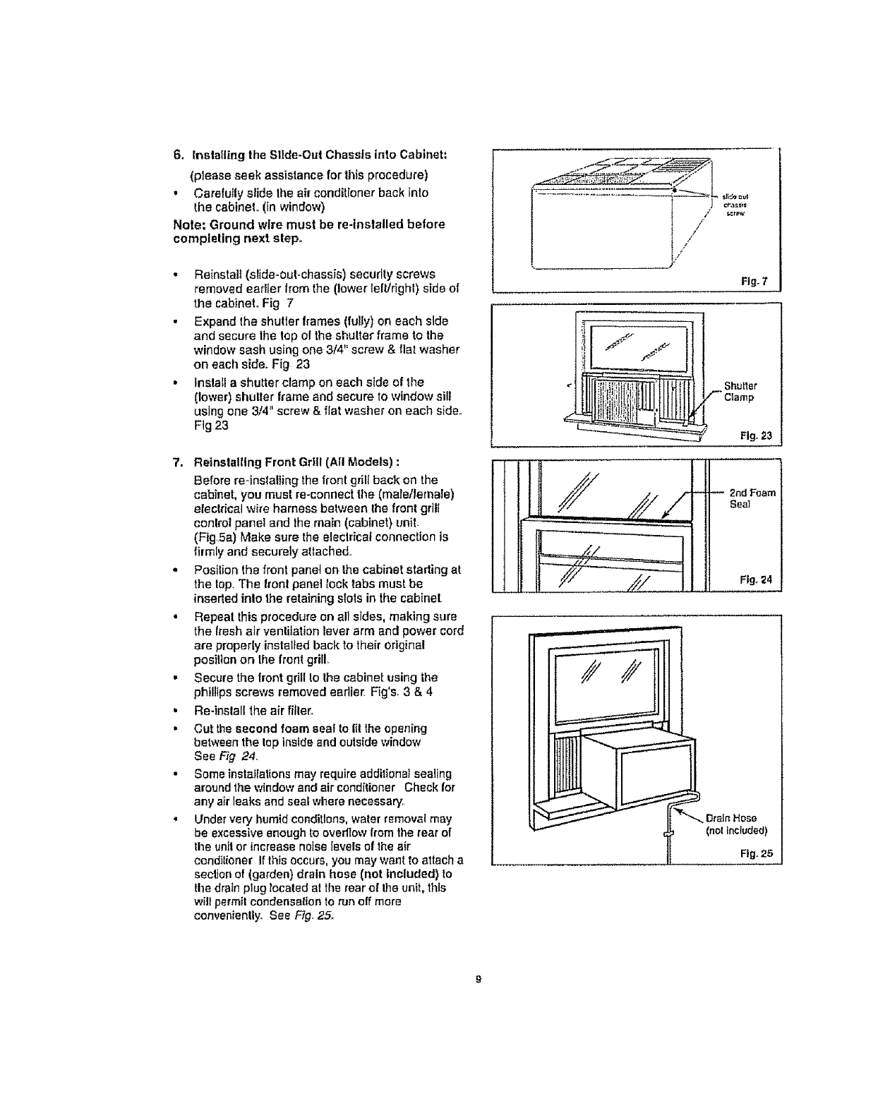
6. tnslaIling the Slide-Out Chassis into Cabinet:
(please seek assistance for this procedure)
• Carefully slide Ihe air conditioner back into
the cabinet., (in window)
Note: Ground wire must be re-installed before
completing next step.
•Reinstall (slide-out-chassis) security screws
removed earlier from the (lower left/right) side o!
the cabinet. Fig 7
• Expand the shutter frames (fully) on each side
and secure the top of the shutter frame to the
window sash using one 314" screw & fiat washer
on each side,, Fig 23
•tnsla[i a shutter clamp on each side of the
(lower) shulter frame and secure to window sill
using one 3/4" screw & flat washer on each side.
Fig 23
7, Reinstalling Front Grill (All Models) :
Before re-installing the front grill back on the
cabinet, you must re-connect the (male]lernale)
eleclrieat wire harness between the front grill
control panel and the main (cabinet} unit.
(FigSa) Make sure the eleclrica/connection is
firmly and securely attached.,
• Position the front panel on the cabinet starting at
the tap.,The Iront panel lock tabs must be
inserted inlo the retaining slots in the cabinet
• Repeat this procedure on all sides, making sure
the fresh air ventilation lever arm and power cord
are property installed back to their original
posil_en on Ihe front grill
• Secure the trent grill to the cabinet using the
phillips screws removed earlier Fig's. 3 & 4
• Re-inslall the air fitter.
• Cut the second foam seal to lit lhe opening
between the lop inside and outside window
See Fig 24
• Someinstaf[ations may requireadditional sealing
around the windowand air conditioner Check for
any airleaks and seal where necessary,
•Under very humid conditions, water removal may
be excessive enough to ovedtow from the rear of
the un[I or increase noise levels ol the air
condilioner If thisoccurs, you may want to attach a
secIJen of (garden) drain bose (not Included) to
the drain plug located at the rear e! Ihe unit, this
will permitcandensalion to run off mare
conveniently. See Fig. 25.
[//
Fig.7
Shutter
_2rid F_em
Seal
Fig, ;Z4
_Drain Hose
(nolincluded)
Fig.25
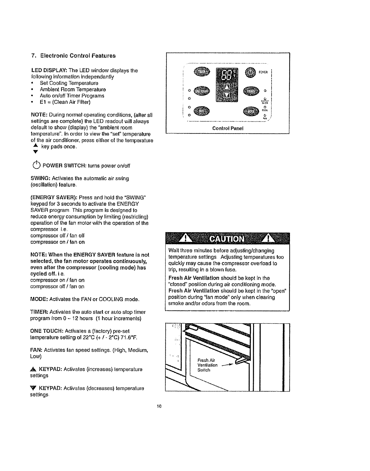
7, Electronic Control Features
LED DISPLAY: The LED window disptays the
following information independently
• Set Cooling Temperature
• Ambient Room Temperalure
• Auto on!off Timer Programs
• E1 = (Clean Air Filter)
NOTE: During normal operating condilions, (alter all
settings are complete) the LED readout willalways
delautt to show (display) the "ambient room
temperature"., Ir_order !o view the "sol" temperature
of the air conditioner, press either of the temperature
A key pads once.
Y
o
o
Control Panel
O POWER SWITCH: turns power on/off
SWING: Activates the automatic air swing
(oscillation) feature,
(ENERGY SAVER): Press and hold the "SWING"
keypad for 3 seconds to activate the ENERGY
SAVER program This program is designed to
reduce energy consumplian by limiting (restricting)
operation of the fan motor with the operation of the
compressor i.e.
compressor off /fan off
compressor on /fan on
NOTE: When the ENERGY SAVER feature is not
selected, the fan motor operates continuously,
even after the compressor (cooling mode) has
cycled off, is,
compressor on /fan on
compressor off /fan on
MODE: Activates the FAN or COOLING mode.
TIMER: Activates the auto start or auto stop timer
program from 0 -. 12 hours (1 hour increments)
ONE TOUCH: Activates a (factory) pre-set
temperature setting of 22"C (+/- 2_C) 71.6"F.
FAN: Activates lan speed settings. (High, Medium,
Low)
,,_ KEYPAD: Activates (increases) temperature
settings
Xr' KEYPAD: Activates (decreases) temperature
settings,
Wait three minutes before adjusting/changing
temperature settings Adjusting temperatures too
quickly may cause the compressor overload to
trip, resulting in a blown lUSeo
Fresh Atr Ventilation should be kept in the
"closed" position during air condilfoning mode°
Fresh Air Ventilation si_ould be kept in lhe "open"
position during "fan mode" only when clearing
smoke and/or odors from the room..
10
POWER:
Press the POWER keypad to lure the unit on/off
ATEMPERATURE SETTINGS:
Press the up keypad to increase the set (operaling)
temperature of the air conditioner Each time lhe
keypad is pressed the temperature is increased as
feflows;
2°F (FarenheIghl Scate) Maximum Setting 90"F
I"0 (Celsius Scaie) Maximum Setting 31°C
Y TEMPERATURE SETTINGS:
Press the down keypad to decrease the set
(operating) temperature of the air conditioner+ Each
lime the keypad is pressed the temperature is
decreased as Iollows;
2°F (Farenheight Scale) Minimum Setting 60'+F
1°C (Celsius Scale) Minimum Setting 16+C
SWING:
Press the SWING keypad to activate the automatic
air swing (oscillalion) feature+ "The green pilot light
adjacent to the SWING keypad wil! illuminate,
identilying the selected mode is operational+ The
vertical louvers will oscillate back and forth (side to
side) automatically sweeping cold air allernately for
comfortable cooling+ To stop the air swing feature,
press the SWING keypad again, the green pilot light
adjacent to the keypad will go off..
(ENERGY SAVER):
To activale the ENERGY SAVER feature, press and
hold the "SWING" keypad for 3 seconds.
The green pilot light directly above the ENERGY
SAVER mode will Illuminate, ldent;-y+ngthe selecled
mode is operational. The ENERGY SAVER program
helps Io reduce energy (elecldcily) consumption by
controlling (limiting) operation of the fan motor wilh
tPieoperation (cycles) of lhe compressor. I+e,+
compressor off Ifan off
compressor on tfan on
If the ENERGY SAVER feature is not activated, the
fan willoperate continuously,even after the
compressor has cycled off. ire
compressor on /fan on
compressor off I|an on
NOTE: The energy saver feature operates in
"cooling" mode only.
direotly above the COOL or FAN mode wil!
Ifluminale, identifying the selected mode Ls
operational+
TIMER:
Press this keypad to activate the "auto slart Iauto
slop" timer programs. Aulo start]slop programs can
be programmed from 0 - 12 hours. Each
depression of the TIMER keypad will increases the
selected lime in 1 hour increments.
AUTO _START:
Before activating the "aulo -start" program, you
must first select (set) the operating conditions of the
air conditioner_(Le+temperature selling and fan
speed). Once the settings are complete, the air
condiliener must be switched off. (non-operaliona!)
Depress theTIMER keypad and the auto-start time
will appear in the LED display, select the requtred
time (0 .- 12hours) and the air conditioner will start
automatically at the established time.
AUTO +STOP:
Turn the air conditioner on and setec{ the required
operating condilions+ (i.e temperature setting and
fan speed)_ Depress the TIMER keypad and the time
will appear in the LED display, select the required
auto stop lime, (0 - 12hours) and the air conditioner
will slop automatically at the established time.
NOTE: It Is not possible to operate both the
"auto-start" and "auto-stop" feature within e
single program. All auto-timed programs are
automaticaUy erased after the set program is
complete.
ONE TOUCH=
Press this keypad to activate a pro-set (factory)
temperature setting of 22°C + /- 2+C (71+6°F)+The
air conditioner wiIt operate and maintain the Indoor
temperalure at this selling..
MODE:Press this keypad to select the appropriate
operating mode. (Far+ !Coo!) Each depression of
the MODE keypad witt alternate between the
"COOUNG" and "FAN" mode The green pilot ligh!
FAN:
Pressthiskeypadtoactivatelheappropriatefan
speedselling°EachdepressionelIhekeypadwill
alternatethroughHigh,Medium,Lowfanspeed
oplionsThegreenpilotlightdirectlyabovetheFAN
speedoplionwill illuminate, identifying the lee
speed selected.
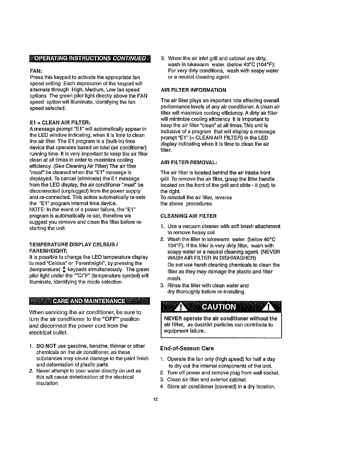
E1 =CLEAN AIR FILTER:
A message prompt "El" will automatlcally appear in
the LED window indicating, when II ts time to clean
the alr filler, The E1 program is a (built-In) lime
device Ihal operales based on Iolal (air condilioner)
running lime, I! is very imperlant to keep the air filler
clean at all times in order to maximize cooling
efficiency:, (See Cleaning Air Filler) The air filter
"must" be cleaned when the "Et" message is
displayed+ To cancel (eliminate) the E1 message
from the LED display, the air condilioner "must" be
disconnected (unplugged) from lhe power supply
and re-connected+ This action aulomalieally re-sets
the "El" program internal time device.
NOTE: In the event of a power failure, the "El"
program is aulemalically re-set, therefore we
suggest you remove and clean lhe filler before re-
sla_ing the uniL
TEMPERATURE DISPLAY CELSIUS /
FARENHEtGHT:
II is possible to change the LED temperature display
to reed "Celsius"or 'Farenhetght", by pressing the
(iemperature) _ keypads simultaneously. The green
pilot light under Ihe "C/°F" (temperature symbol) will
tlluminale, identifying ihe mode seleclion
When servicing the air conditioner, be sure to
turn the air condilioner to lhe "OFF" position
end disconnect Ihe power cord from the
electrical otitlet.
3_ When Ihe air inlet grill and cablnel are dirty,
wash In lukewarm water, (below 40°C (104"i:):
For very dirty conditions, wash with soapy water
or aneulra! cleaning agent.
AIR FILTER INFORMATION
The air filler plays an important role effecttngoverall
performance levels of any air condilioner, A clean air
tiller will maximize cooling elficiency. A dirty air filter
wilt minimize coottng efficiency. II is important to
keep the air filler "clean" at all limes,This unit is
Inclusive of aprogram that will display a message
prompt "Et" (= CLEAN AIR FILTER) in lhe LED
display indicating when It Is time to clean the air
filler>
AIR FILTER REMOVAL:
The air filter Is located behind the air intake front
grill,, To remove lhe air filler, grasp the filler handle
located on the Ironl of Ihe grill and slide - il (out) to
the righL
To reinstall the air filter, reverse
the above procedures,
CLEANING AIR FILTER
1. Use evacuum cleaner with soil brush attachment
to remove heavy soil,
2. Wash the filler tn lukewarm water, (below 40°C
|04"F): If the filler is very dirty filter, wash with
soapy water or a neulra! cleaning agenL (NEVER
WASH AIR FILTER IN DISHWASHER)
Do not use harsh cleaning chemicals to clean lhe
filter as they may damage the plastic and filter
mesh°
3. Rinse the filler with clean water and
dry thoroughly before re-installing.
il lr, ! ., ,tl !'till
NEVER operate the air conditioner without the
air filter, as dust/dirt particles can contribule to
equipment failure,
1. DO NOT use gasoline, benzine, thinner or other
chemicals on the air conditioner, as these
substances may cause damage to the paint finish
and deformation of plasltc parts<
2. Never attempt to pour water directly on unit as
lhls will cause deterioration of the electrical
lnsulatlon,
End-of-Season Care
1o Operate the fan only (high speed) for half a day
to dry out the internal componenls of the unit.
2. Turn off power and remove plug from wall sockeL
3. Clean air filter and exterior cablnaL
4+ Store air condilioner (covered) in a dry location.
12
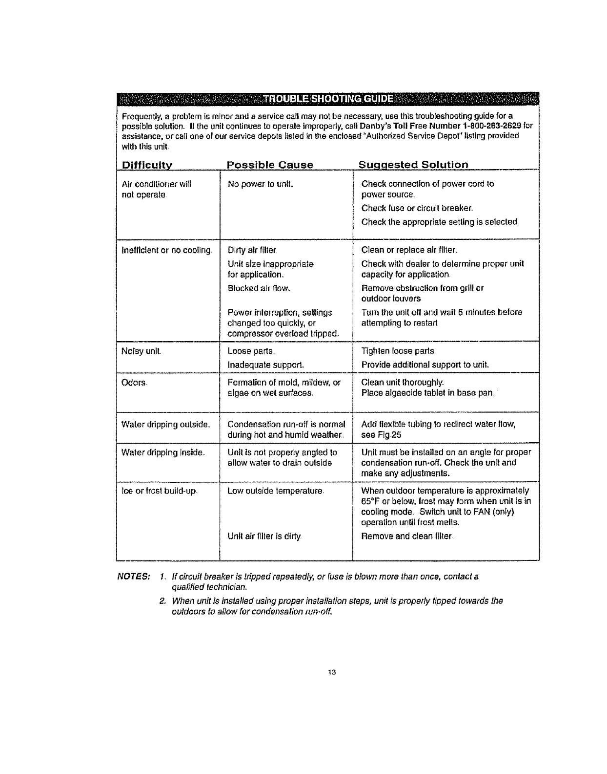
Frequently,a problem is minor and aservice call may not be necessary, use thistroubleshootingguide for a
possible setulion If Ihe unit continues to operale improperly+call Danby's Toll Free Number 1-800-263-2629 for
assistance, or call one of ourservice depots listed in the enclosed "Authorized Service Depot"listingprovided
with thisunit
Possible Cause
No powerto unite
Difficulty
Air conditioner will
not operate.
Dirty air filter
Unit size inappropriate
for application..
Blocked air f_ow,.
Inefficient or no cooling+
Power inlerruplton, setlings
changed too quickly, or
compressor overload Iripped_
Suggested Solution
Check conneclion of power cord to
power source.,
Check fuse or circuit breaker.
Check the appropriate setting +sselected
Clean or replace air filter.
Check wlth dealer to determine proper unit
capacity for application
Remove obstruction from grill or
outdoor louvers
Tum the unit off and wait 5 minutes before
attempting to restart
Loose pa_s
Inadequate suppod_
Form_mn of mold, mildew, or
algae on wetsuffeceso
Water ddpping outside° Condensation run-off is normal
during hot and humtd weather.+
Water ddppIng Inside. Unit is not properly angled to
allow water to drain oulside
Ice or frostbuild-up_ Low outside temperature,
Unil air filler is dirty
Tighten toosa paris
Provide add+lional support to unit.
Clean unit thoroughly.
Place algaeoide tablet in base pan+
Add flexible tubing to redirect water flow,
see Fig25
Unit must be installed on an angle for proper
condensation run-off. Check the unit and
make any adjustments.
When outdoor temperature is approximately
65"F or betow, frost may form when unit is in
cooling mode. Switch unit to FAN (onty)
operation unlil frost molls+
Remove and clean filter.
NOTES: 1. If circuit breaker is tripped repeatedly, or fuse is blown more than once, contact a
qualified fechnlctano
2.. When unit is insta!ted using proper instailafion steps, unit is propefly tipped towards the
outdoors to a/few for condensation run+o_.
13
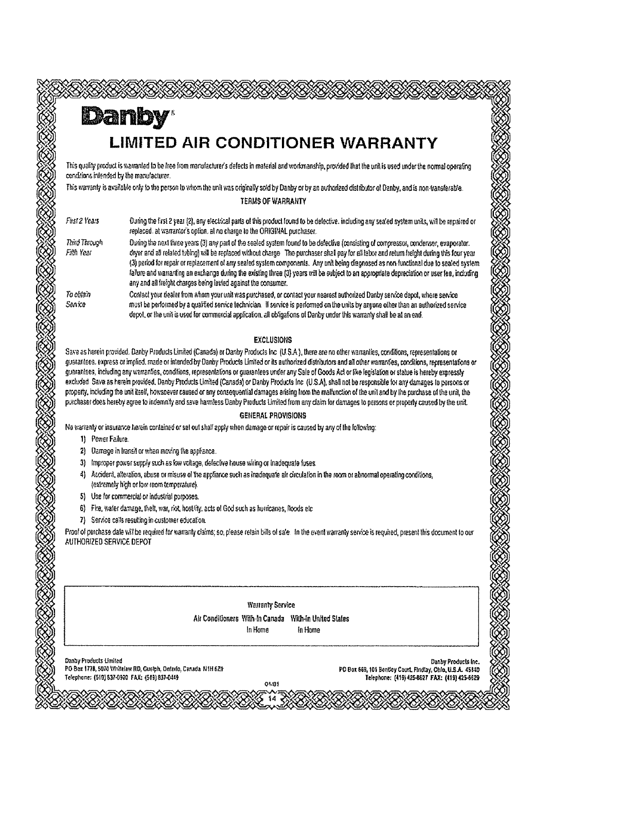
LIMITED AIR CONDITIONER WARRANTY
ThZeqv_li'rlproduclisv,zrranledtobei_ee:hummerol_clurVsdefectsinmaleHaland;vodoT,enship,p_,_dedthattheunitisusedunderthenormeJu_ra_ng
con_!im%inlen_d_ithe rnanubctane_'.
This_,,,'a,',,_nl'tisava_b]_c,_l),b Iilo personto'_','tto.'T,Lheunity;asorig_na!_ac,_dbyDanbyorbyanauthorizedd[_tr;b_AerorO._nby,andLsnon_an,_[ei'aL/e
TERJ.{:_OFWARRANTY
Fi_.r2_°ea;s
Tods_a_n
SGn'Le
0_dngt_e_1st2$.'eaf[21,anyet_L,i:_ipa_ ot_is p_oductfound{e_ delec_ve,includingart/ se_.'__._emun_ '_,ilt_ _ep_Jtedor
repl,_d,a_,s_rran'_ef'soption,atnocha_geIotheORIGI_tALpu_¢h_e_.
Outingthene_tt__eeye_s(3]_}'padottheseel_ay_t_found[obedetectl,le(_o_%t_ o[co_re:-sel,condenser,e','eF_ratoro
de'erer,da_Jrelaled_blro)wiHberep!_,oedwi_boutoha_geTheputchasersha_payfor_ttabe_andtetum_e_ghlduHng_stou_yeas
(3)ped_|o__ep,zirorrep]a._rr,enlo!art),sealedsystemcu_ponenL_.._y nr_beingo'b_'_o_edas:nonf_nctbnaldue1os_a_ system
latureandwa#a.n_inganex_har,geduring_ existing]hree(3}years_1 be_bjc-.dtoanapero_atedep_at_o_oruserlee,bduo_ng
any_.ndalllleioh(_9_beingleviedagains!Lhe.oo_um_.
ConlaB_.,'ourdealellnom_41nmyourun_!waspurchased,orr,_tacl yournea_e_lauthorizedbnby se_ depol,wholeso,ice
muslbepulo_medWaquK_ed_n,icelechnici_II_,'iceispeHon'ne_.onlheun_L_by_i'_eolhe_lhananauthmizedsen'ice
dep:,l,orlheunitL_used[orcomm_cblapplica_n,a_lob_iga_.onsu(O_r,byunderthisy,'arr_tyeheUbeatnnend.
ILY_CLUSIOIi_
Save_:shereinp_ovid@.OanbyP_nducteU_iled(C_nade)orDaub?P_'_L_SInc(U_SA),therearenoolhetwana.ntiee,condHJons,rep_e_ntalionsDe
guer_tee_+exp__s_or_pli_n_deorin_er_l_b_OanbyPr_uc:L_Limil_oritseuthoHznd_i_Irlbularse_ a_otherv_rrar,'6_,_i1_ne,t_ _]T.'_neot
gu_rantee.,Lincbdingany\v_ean_ir::s,mn_4ion_,_eptesent_Ibnao_gaa_anleea_er anySaleofGoc_s_ orl_elend.fono_statueIshe_e_express_
exelud_Sa>'aashereinp_o'.'Tded.O_nbyPI_ud..:,U_:led(C_d_)_ DanbyProdu_LsInc(US.A),sh_llnotberesponsive1o_anyd_agesIo_nons or
prop_f.Inclu,::ILngtheanilil_el_,be_,.,so¢_f_u_ or_nyoon_aq_nlia]damagnse_g Ironthe_,elIun_noftheunitendbylhepa_r.h.a_oltheunil,lha
p,_rehase_d_she_y agreeIoin_en,n;t__ we harassOan_!PIo_u_U_d_ floraon)'da,imford_rnage_Iopelsonsorptol_il,/causeilbylheun_
6EttERALPROVISIOIIS
Hav_a#enl7ori_sm_r,':ehe,'elnenr,lain_orsoleulshel_app_f,_hendominieorrepairieca_d by_y oflheIollo*ing:
2) O_mageini_ne;1orwhenm_,_n!ll_,ne_iance.
3) imp,_p_rp_/`_rs'.xpp_$_s_'x`h_sbwv`_t_`ge_defec_._h_use.,'_Iingorinadnquate|_ses_
4) k_der_La_e_ati_n_ubus_m_u_lheepp5ance_Bqesinadnqunle_rd_aibn_nLh_m_tebn_rma_pem_in_r`_ndi._ne_
5) Useforcorn,_cia_eHn_ustH_Ipur_s.
6) EIre,,t,alerd_'_age,lhell,_hf_ho_y._._olGodsuchaahu_dr;a_s,_oodaeln
7) Ser,Hcec._sresui'.ingin_stom_reducat;or_
Pr_#olpwch_+sedalev,i!tbo_equilndlerwenenl'td;_im_so,p!easereteinbillsofsa'eInthe_,'enl?,'an'._.n_ee_ isreqvi_,p_esenIthisdocumenltoour
AUTHORIZE_SERVICEDEPOT
t'la_=en_Sen,ice
kit CendilionueWill.lnCanada Y/i_-InLlnHedSlales
InHome InHome
OanbyP_oduc_LJrnHed Dz_nt,yFtoducL_L,'¢.
POBo_1T/I, _70 \Vn_dawRO,Guelph,OnfzHo,C_nad_?tiP]eZ9 PO8oz_g, lO| _n_y Court.F_n_ay,Ohio,U'e._ ,Ke_O
To,phone:(519)_7-09_0 FAX:{_t_}8_7-0_4ex ?elephor,e: [41_u),12_..aG;_'_FAX:(I19]42-_29
Page
Introduction ................................................................. 16
Fiche signal_tique .......................................................... 16
Specifications e_ectdques ...................................................... 17
Conseits d'_conomie d'6nergie .............................................. 18
Installation dans la fen_lre ..................................................... 18
Instructions de fonctionnement ................................................. 25
Precautions et entretien ......................................................... 26
Guide de d_pannage ........................................................ 27
Garantie ................................................................. 2B
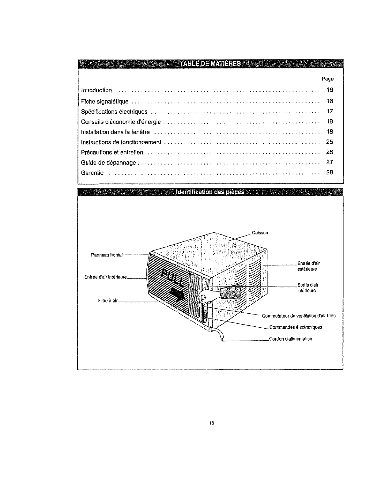
.Sortie d'air
In1_ieum
Commuteteur de venl_al_ond'air frais
.Commandes _lec(ronlques
.Cordon d'a_[mentalton
15
Nous vous remercions d'avoir cholsi un climatiseur de chambre Danby Silhouetle pour reiroidirvolre togemenL Ce
manue_d_utilisation et d'enlretien lournit les renseigr_ements necessatres pour prendre soin el entrelenir volra
nouveau cl[ma]Jseur de p_cs.. S'il est adequatement entrelenu, volta climatiseur vous donnera de nornbreuses
armies d'ulitisation sans probl_me. Pour _viter route difficutt_ d'tnslallatlon, veuitlez ]ire tes pr_sentes instructions,
compf_ternen{, avanl d'Jnstailer et de fairs foncfionnerre|re appareil
REMARQUE :Cet appa{eil n'a PAS6t_ con_u pour une insla]lalion _ |ravers une paroI
,&.li|re de r_f_rence, vous pouvez agrafer hcelle page une copte de votre requ d'achal de l'appareiL Inscrivez les
rensetgnernents suivants foumis (sur la plaque s]gnal_tique du fabricant Iigurant sur le cet6 droll de i'appareil au-
dessus du cordond'aiimentalion). Vous aurez besoin de ces renseignementssi vous conlactez un represenlent du
Service _ la cllent_le.
Num_ro de mod_le:
Num_ro de sgrie:
Date de I'achat:
Nee el adresse al!!concessionnailre:
Veuillez vous reporter & la seclion du d_pannage figurantdens ce manuel d'ulilisation et d'entretien, si I'appare]l ne
fonctionnepas correctement. Si cette suggestion ne r_soul pas le probl_me, contactez un repreeentanl autorisd
des services ou appelez directement Danby, sans frays,au num_ro : 1-800-263-2629
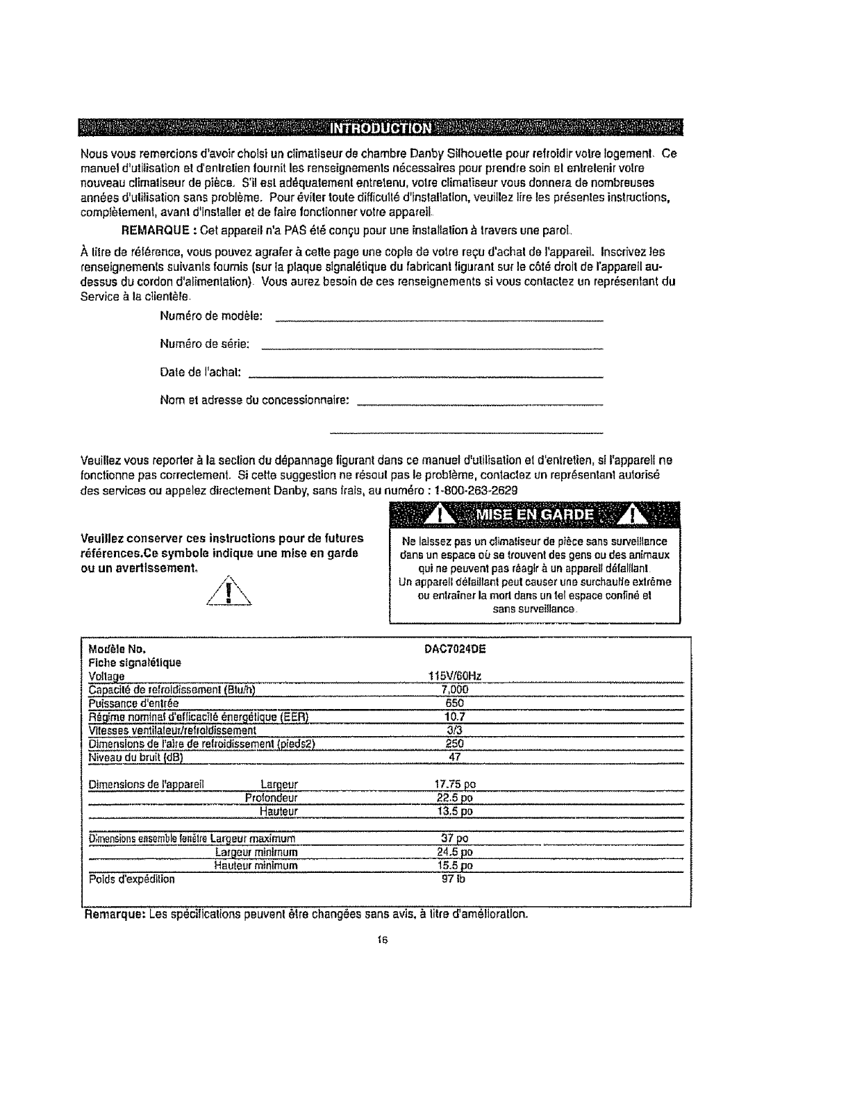
Veuillez conserver ces instructions pour de futures
r_ferences.Ce symbole indique une raise en garde
ou un avertlssement,
Ne laissez pas un climaliseur de piece sans suwetfl_nce
6ans un espace ouse trouvent des gene ea des animaux
q_i ne peuvent pas r_.agtr_. un apparell d_falllanl
Un appare[I d_[aillant peut causer une surchau_e extreme
eu an|tanner la marl dens un tel espaca confin_ el
sans surveillance
Mod_]e No,
Fiche sfgna1611que
Vol!age
Capacil_ de relroldiesemenl (BtuR_)
Puissance d'entr_e
R_gima namina! d'ellicac!!_ 6nerg_!j_ue (EER)
Vltesses ventilateur]_elmldissement
Dimensions de l'a)_ede relroidissement (pieds2)
Niveau du bruit {dB)
DAC7024DE
1 !5VI60Hz
7,000
650
10.7
at3
250
47
Dimensions de t'sp_areil Largeur 17.75 _o
Profondeur 2;':'.5po
Hauteur 13,5 po
D;mensi_nsensemblele_.lre Largeur maximum 37 _o
La_'geur minimum 24.5 po
Hauteur minimum 15.5 po
Polds d'exp_di_ion 97 Ib
Remarque: Les specifications peuven! 6|re changees sans avis. & It|re d'ameltoratlon.
16
"1 , _:'"i -"¸. ....................
memm.'+] _ _ I;;I[,H.+_I[H,_[,.']I_I_il;| [t,]i.lJ+"Ira,were
Teus_esc,lblagesdolvent_treconlormessux
codes_leclriquesIocauxe!nationauxetdoivent
_treinstali_sparun _lecbicienqualili_,+Sivous
avezlamoindm questionau sujetdes _nstructions
cl-dessous, contactez un _tectticten quallft_.
2. V+rifiez la fournfture d'aiimentation +lectdque
disponible et r+solvez lout prob/+me de c&blage
AVANT d'instalier et de talrefonctienner cat
appareil
3, Ca ctimatiseur & 115V utilise 12 amperes ou seine
de puissance nominalset peut +Ire utllis_ avec
route prise de courant domestique de but general,
ad+quatement c&bi+e. Volr Is Tableau I pour les
specifications pour circuitde derivation individue!,.
4+ Pour votre s+curit+et votre protection, cat apparetl
est sis _ la masse par la fiche du cordon
d'alimentafion Iorsqu_el/eest branches dane une
prise murals correspondents, SI vous n'+les pas
cedain que votre pr_sede courantmurals est miss
la masse ad+qualemenl, veuiliaz consulter un
+lectricien qualift+.
La pr+semura_e(_ 3broches) doit correspondre&
ta fiche & 3 b_oehessur le co_donde service Iouml
avec I'appamiL N'utilisez PAS de fiches
d'aclaptafion_ Voir le Tableau 2 pout lee
rensefgnements sur les prises de courantst tes
fusibles,, S'il est n_cessatre d'utiliser une ralfonga
_lectrique pour branchervotre climaliseur, utilisez
une rallonge _lectrlque approuvde pour -
cIimatiseur ,, exclusivement, (dtsponible dens la
ptupad des quinca}tlerles}
6, La plaque slgnal+tlque sur t'apparetl contient des
donn_es +leclriques el lechntques; ells se trouve
surle c+l+ droit de ]'appareil,au-dessus du cordon
d'atimentation
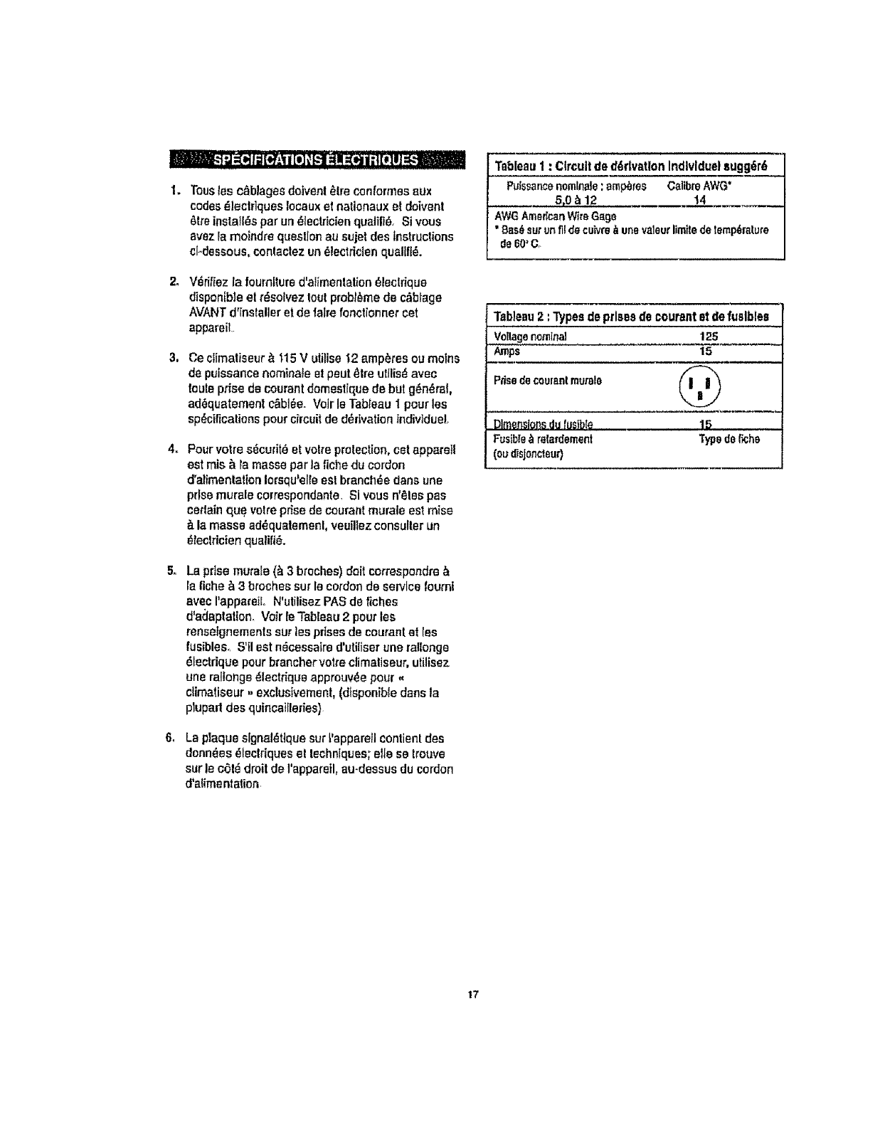
Tableau 1 : Circuit de derivation Indlvlduel sugg+r6
Puissancenominals:amp_tes C_,libreAWG"
5,0 b12 14
AWGAmericanV_teG_ge
"Bss_ surunfit decuk,re_unevaleuriimitedetemperature
de60+Co
Tableau2 :Types de prises de courant st de fualblea
Voltagenomina] 125
Asps 15
P_sedecoman!murals _-ii _"_
Dimensionsdu_'uslbte 15
Fusible_ r_ta_lement Typede_ha
(ou_sjoncteur)
17
Votre cllmatlse_ui"de pTEcee_t con_u pour _tre 4
d*une grands efficacit_ dens l'_conomle d'_nergte_
Po_r l'augmenter encore, veuitl_zsuivre fes
recommendations ci-dessous :
I S_lecltonnez un r_glage du Ihermostal qui
convienne aux beeolns de volre conlort el laissez
le thermoslal a9 r_glage chotsi
2. Le:iiilr_& ai; esi ff_s efficace pour _iiminer ies
parlicules en suspension dens I'air. Gardez
toujourste li!l_e propre.
3. UlilJsez des draperies, ddeaux ou stores pour
emp_cher tee rayons directs du soleil de _chaufler
la piece, mais n'obslruez PAS le climeliseur,
Permeltez _ I'arr.de circularautour de I'appareI!,
san's"5bstacle.
_l_|l" I'= II " " t "
_ Pour_viler ia possibiltt_ d'une blessure
corporelle,d6branchez I'altmentalionde
I'appare event son nstalaIion ou son |
entrelien.. ]
Outlls n_cessaires pour installation dane une len_lre
Toumevis A l_le Philips et plate
Perceuse _lectdque M_chede 1/8 po de diarn
Crayon
Ruban _ mesure
C[seau×
C{_,r_glable
Niveau & bulls
Pour _viter les difftcult_s d'Inslallaflon el de
toncttonnemenl, veulllez fire lee Instruclions
attenlivement.
Votreclimatiseur de ehambre a _t_ con_upour une
inslaliation lacIle dans une fen_,l_e&ch&ssis&gui_lotine
simple ou double.
REMARQUE: Col appareil na pas _,t_con_u pour des
{en_l{esvedicaies (de typecoulissant)ou pour 8lre
instaIl_ #,traversuneparei REMARQUE: Conservez le
carton d'exp_dilion ette mal_riel d'embal!age pour fulur
enlrer,o_age ou transpod de rappareiL O_ezPapparelldu
Commencez & fairs fonclionner volts climallseur
avanl que rair exl_rieur ne soil chaud el
inconlorlable. Cola 6vitera une p6rioded'inconfort
Iorsque Pappareil commence _, refroidir la pi_ce-
5, Quand los lemp_ratures exl_deures sonl assez
frafches, ulilisez seulemenl te ventilaleurE la
vilesse ELEVI_E, MOYENNE OU FNBLE (seton
volre mod_le). Cola fail circular t'atr]nl_rieuret
produil un certain relroidissement conforlable el
utilise moins d'_ilectdeiI_ que lorsqu'on fail
foncfionner le climaliseur en mode reffoidissement
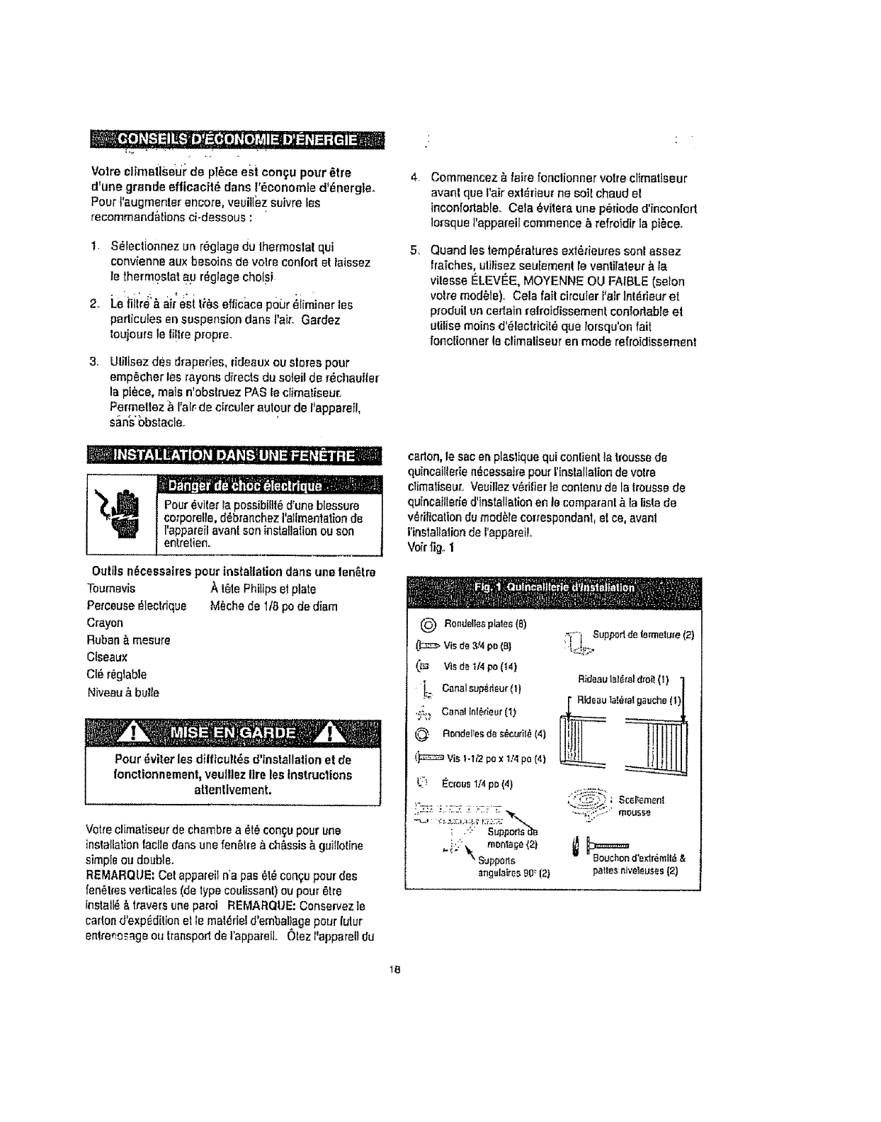
carton,le sac en ptaslique qui conlientla lmusse de
quincai!ler_en_cessaire pour tlnstallalion de volte
cl_imaliseur.Veuillez v6rifierle conlenu de la lrousse de
qufncaillede d'inslallation en la compa_anl&ta lisle de
v_riffcation dumod_le correspondent,et re, event
l'inslailalion de I'appareiL
Voir fig. 1
1@
Comma le compresseur se l_ouve du c6t_ des
commandes de I'unil_ (oSt_ droll), ca cSt_ esl plus
Iourd et plus di_cile & manipuler. Un soutien
inappropri6 du c_t_ des commandos de f'appareii
pout causer des blessures et endommager i'appareil
et d'autres biens mobitiers C'est pourquoi 1tesl
recommand_ qua quelqu'un vous aide au cours de
rinstatlation de col appareil.
Volre eppareil a _l_ con_u pour qua la condensation
s'_vapore dens des condilions normales° Cependant,
en presence d'une humidil_ extreme, un surplus de
condensation paul provoquer un d_bordemenl de ta
cuvette de base vers re×t6rieur L'apparell dolt _lre
inslall_ de letle sorte que ['_coulementde ra
condensation ne se d_verse pas sur des passanls ou
sur des propri_l_s avoislnente&
Une connexion de luyau de dralnage (& I'exclusion du
luyau) est fournia pour r@achemfnerle d_bordement de
la condensalion. Voir fig. 25.
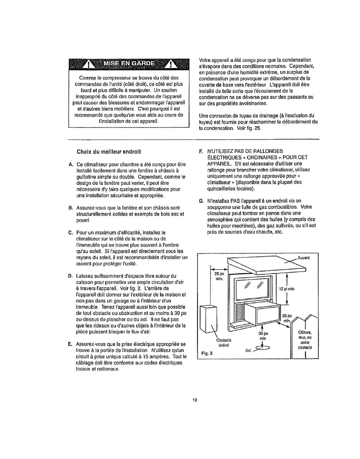
Cholx du meilleur endroll
A. Ce climatlseurpour chambre a _t6 con_u pour _tre
tnstall_ facilemenl dens une fen_lre & chassis
guillotine simple ou double., Cependanl, comme le
design Be la fen_tre pout varlet, il peul _tre
n_cessaire d'y loire quelques modificalions pour
une inslaltatton s_curtlaire et appropri_eo
8. Assurez_vous que la fen6tre et son ch_,sslssont
structur!!lament solidus et exempts de bols sac el
pourri.
O. Pour un maximum d'elficacit& Inslallez le
climatiseur sur le o6t_ de la maison ou de
t_immeublequi se tr0uve plus souvenl & I'ombre
qu'au soleiL Si I'appareit est directement sous les
rayons du sole& i! est recommandable d'Inslalter un
auvenl pour prot_ger I'unit_.
!& Laissez suffisamment d'espace libra autour du
caisson pourpermeltre une ample circulation d'air
& travers rappareiL Vo[r lig, 2. L'ard&re de
t'appareit dolldonner sur f'ext_rieur de ta maison el
non pas dens un garage ou & i'fnl_rieur d'un
immeuble. Tenez I'appareil aussi loin que possible
de tout obstacle ou obstruction el au moins & 30 po
au-dessus du plancher ou du sol, II ne faul pas
que les rideauxou d'aulres objels & I'int_rieur de la
piece puissant bloquer le fluxd'aic
Assurez.vous que la prise _teclfique appropri_e se
trouve & ta port_e de l'inslallation N'ulitisez qu*un
oircuil & prise unique calcul_ & t5 amp_reso Tout le
c&blage doit 6Ire con_ofme aux codes _lectriques
Iocaux et nallonaux
G_
N*UTILISEZ PAS DE RALLONGES
_LECTRIQUES ,, ORDINAIRES ,, POUR CET
APPAREIL S'il esl n_cessatre d'uliliser une
ratlonge pour braneher volta climaliseur, uliltsez
unlquemenl une raltonge approuv_e pour ,,
climaliseur ,, (disponible dens la plupart des
qutncailleries locales).
N'installez PAS l'appareil & un endroit o'_ on
soupqonne une fuile de gaz combustibles° Volre
climaliseur peut tomber en panne dens une
almosph_re qui conlienl des hufles (y compfls des
huiles pour machines), des gaz sullur_s, ou s'tl esl
pros de sources d'eau chaude, etco
Obstacte rain
19
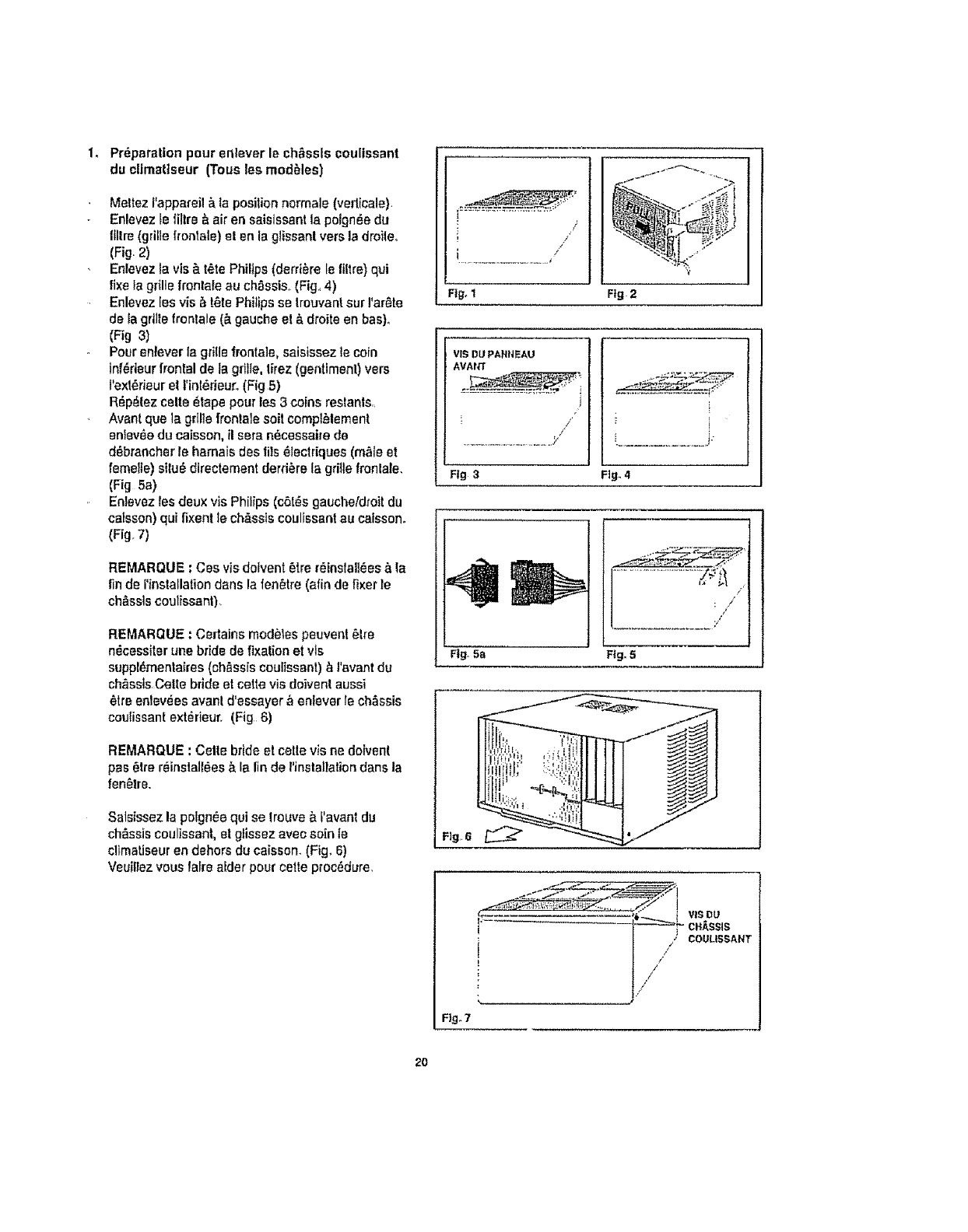
1. Pr_paralton pour enlever le chassis coulissant
du climattseur (Tous]es mod_les)
Meltez f'appareil _ {a position normale (verl[cale)<
Enlevez le filtre _ air en salsissant la poign_e du
IIllre (grille fronlale) _! en la glissan! vers la droile.
(Fig. 2)
Enlevez ta vis&t,_tePhilips (derriere le filtre)qui
fi×ela grille frontale au chassis..(Fig.,4)
Enlevez [es vis _ [_le Phitips se Árouvantsur I'ar_to
de ia grille frontals (_.gauche et & droite en bas)_
(Fig 3)
Pour entever la grille fronta]e, saistssez le coin
lnf_deurfrontal de la grille, lirez (genttmenl) vers
I'ext6rieur el l'intdrieur..(Fig 5)
R_p_tez celte 61apepour los 3 coins restants.,
Avant qua ]a grtl]e frontale soit compl61ement
eniev_e du caisson, il sera n6cessai_ede
d_,brancher te hamais des Ills _lectdques (m_le et
feme!fe) silu6 directement derriere la gd]le fronlate.
(Fig 5a)
Enlavaz les deux vis Philips (c6t_s gauche/droit du
caisson) qui fixent le ch&ssts coulissant au caisson.
(Fig. 7)
REMARQUE : Cos visdo[vent 6ire r_inslalI6es _, la
finde I'installationdans la fen_tre (afinde fixer le
ch&ssts coulissant)
REMARQUE : Certains mod_les peuvent 6tre
n_cessiter une bride de fixation et vls
suppl_mentaires (chassis coulissant),_I'avant du
chassis Ce|le bride et carte vis doivenIaussi
6Ire enlev_es avanl d'essayer ,_enlever Ie ch&ssis
coutissani ext_rieur. (Fig 6)
REMARQUE :Celle bride el cette visne dolvent
pas 6tre reinstall6es & la finde l'inslallation dans la
fen_lre,,
Saisissez la pelgn_e qui se trouve &f'avant du
chassis coultssant, et glissez avec soin le
c!imatiseur en dehors du caisson. (Fig. 6)
Veuitlez vous latre alder pour celte proc6dure.
!/
</
i................................ t /
Fig+1
+>
Ffg-2
VIS DU PANNEAU
AVAIG
i
!/
Fig 3 Fig.4
/
: J
!
Rg_5a Fig. 5
F]g6
Fig,.7
_ L'=" _i"_'L "_",_..-.F ]"
...... _7" cH_.ssla
,......... /j.////i
COULt5SANT
20
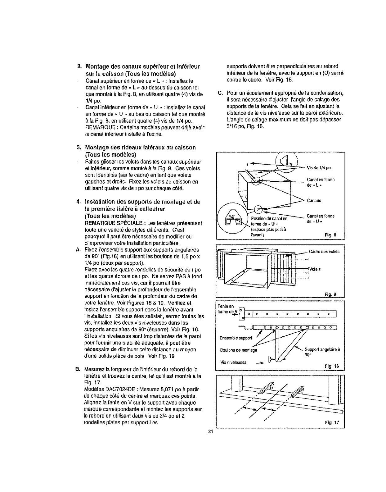
2_ Montage des canaux supdrleur et Infdrieur
sur le caisson (Tousles mod_les)
Canal sup_deur en forms de ,, L ,, :lnstarlez le
canal en forms de ,, L ,, au-dessus du caisson tei
qua montr_ ,_ ia Figo8, en utiIisantquatre (4) vls de
1/4 po,.
Canal inf_fleur en forme de ,, U. :lnslatiez le canal
en fan"he de. U. au has du caisson let qua mantr_
_.la Fig. 8, en uti!isantquatre (4) vis de 1/4 po..
REMARQUE :Cerlains mod_Ies peuvent d_j_. avoir
le canal inf_rieur insta!l__I'ueine_
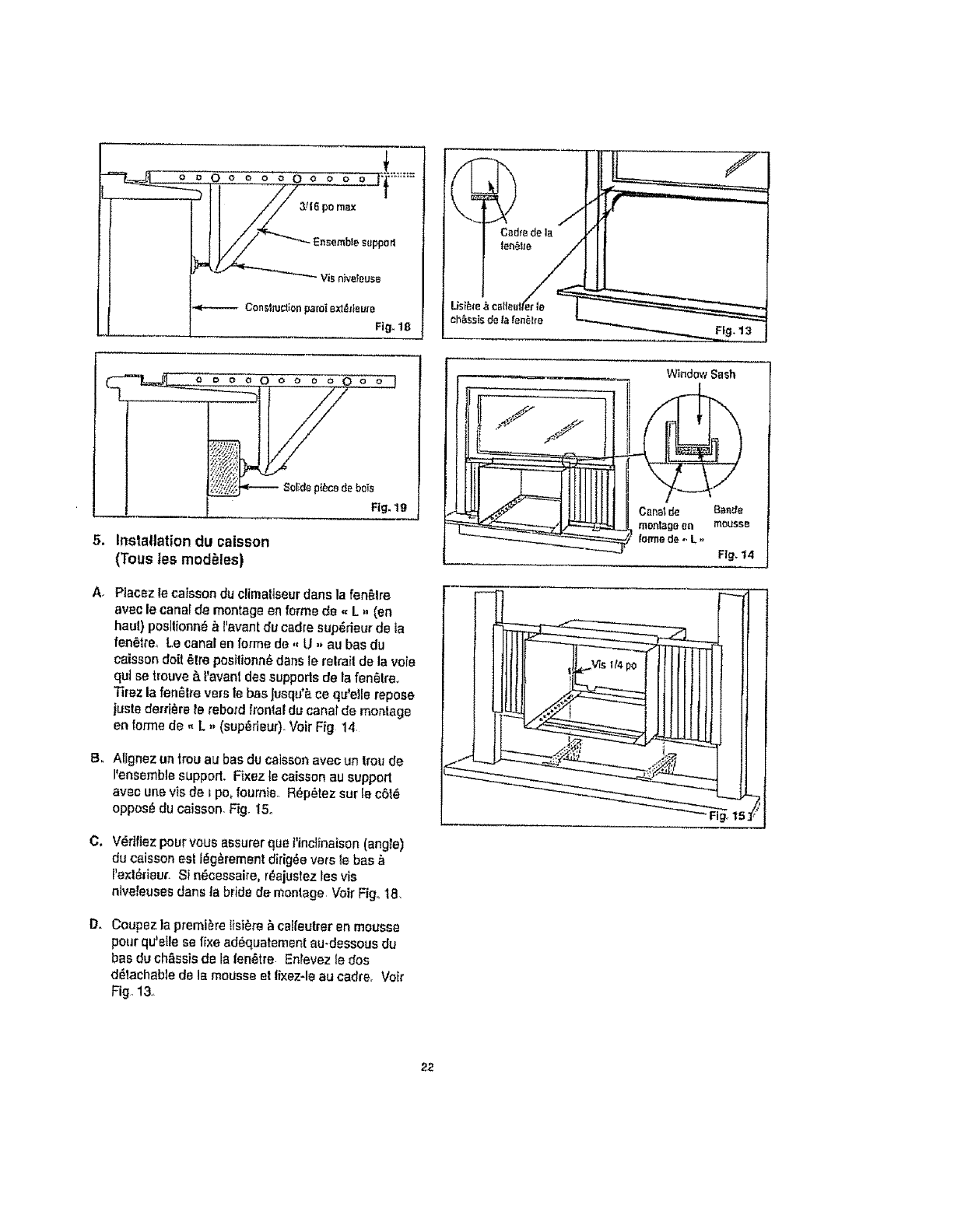
suppods doivent _lre perpend[culalres au tabard
[nf_rieurde la fen6lre, avec te support en (U) serr_
centre le cadre Voir Fig_ 18..
C. Pour un _coulemenl appropfi_-de la condensation,
il sere n_cessaire 6'aJuster l'angle de calage des
supports de la ten,tree Cala se fail en ajuslant la
distance de la v[s niveleuse sur la paroi ext_rieureo
L'angie de caIage maximum ne doit pas d_passer
3/16 po, Fig..18.
3. Montage des rideaux lat_raux au caisson
(Tousles mod_les)
Faites glisser les valets dens les canaux sup_rieur
at inf_fieur,comma ment_ &ta Fig 9. Ces volels
sentldentifi_s(sur le cadre) en tent qua valets
gauches et droits Fixez les voiets au caisson en
utiflsant qualre vis de _po sur cheque c6t_.
4, Installation des supports de montage et de
la preml_re lisi_re ,_ calfeutrer
(Tousles mod_tes}
REMAFIQUE SPEC1ALE :Les fan,tree pr_senlenI
!outs une vart_tbde styles diff6rents, C'est
pourquoi il peut _tre n_cassaire de modifier ou
d'lmproviservolta installation particuli_re.
A, Flxez l'ensemble supportaux supports angufaires
de g0_(Fig.t6) en utilisant tea boulons de 1,5 pox
I/,$ po (deux pa_ support)
Fixez avec {asquat_e rondelles de s_cudt_ de I po
el [es quatre _crous de i po. Ne serrez PAS & fond
imm_diatement ces vis, car il peurrai! _tfe
n_cessaire d'ajuster _aprofondeur de l'ensembte
support en fonct_onde la profondeur du cadre de
volta |entire. Veir Figures 18 & 19. V_rifiez et
teslez t'ensemblesupport dans la fen6tre avanl
Mnslallation, Si vous _.tessalisfait, serrez routes las
vis, instatlez les deux vis niveteuses dens les
supports angulaires de 90° (_querre). Voir Fig. 16.
Sites vis niveleuses son_trapdisfantes de la parot
pourfoumir une slabilit_ adequate, i]peu! 6Ire
n_cessaire de dim[nuer cette distance au moyen
d'une soIide piece de beis Voir Fig. 19
B_ Mesurez la Iongueur de t'inl_rieurdu rebord de la
fen_tre et t_ouvezle centre, tel qu'il est rnontr_ ,_ia
Fig 17.
Med_les DAC7024DE : Mesurez 8,071 po _partir
de cheque c6t_ du centre et marquez ces poinls
AI[gnez la rentsen V sur le support avec cheque
marque correspondents el manlez tes supports sur
Is tabard an utillsantdeux viade 3/4 pe el 2
rondellesplates par supporLLas
/",\
_'_ Via de 1t4 po
_orm_d_- U- dB_U.
(espace p_uspe_it
|'event} Fig. 8
..Cad_e desvolels
.V01ets
Fig. 9
Fenle en
oo.,oo--.,.,,o.
"./is r_tveleuses _ F'_-" '
Fig t6
It_
Fig t7
2t
i
r---'==t=ji--_i-o o o oO o o o o Oo o ]
"7....._ ....
"Fig. 19
5, Inslattation du caisson
(Tous tes mod_les)
A+ Placez le caissondu climaltseurdans la fan,Ire
avec le caner de montage en forme de _,L. (an
haul) posltionn_ ,_l'avant du cadre sup_rieur de la
ien_tte, Le canal en farina de ,, U ,, au bas du
caisson doll +tre posilionn+ dane le relrail de la vole
qut se trouve _.!'avant des supports de la fenOlra_
Tirez la fen_lre vers 18bee Jusqu°_ce qu'elle repose
juste de+ri+re +erebord frontal du canal de montage
en lorme de - L ,, (sup+rieuO+Volr Fig 14
B. Allgnez un trou au bas du calssonavec un Irou de
I'ensemblesupport+ Fixez te caisson au support
aveo une vis de i po, fournie.. R+p+tez sur le c6t+
oppose du caisson. Fig+15.
C. V_dfiez pour vous assurer qua t'inciinaison (angle)
du caisson est I_g_rement dirig_e vars te bas &
Pexl_fieur. Si n_cessaire, r_,ajustezles vis
nivefeuses dens |a bride de montage Voir Fig, t8
D= Coupez la premiere lisi_re _ calfeetrer en mousse
pourqu'efle se fixe ad6quatement au.dessous du
bas du chassisde la |en6tre Entevez le dos
d_lachable de la mousse et lixez-le au cadre. Voir
Fig. 13.
WindowSash
ti S_ l tItIf t_ I
L.-_
Canalde eande
_,_E:_7_L -_ montagean mousse
forrnede_L ,, Fig.t4
22.
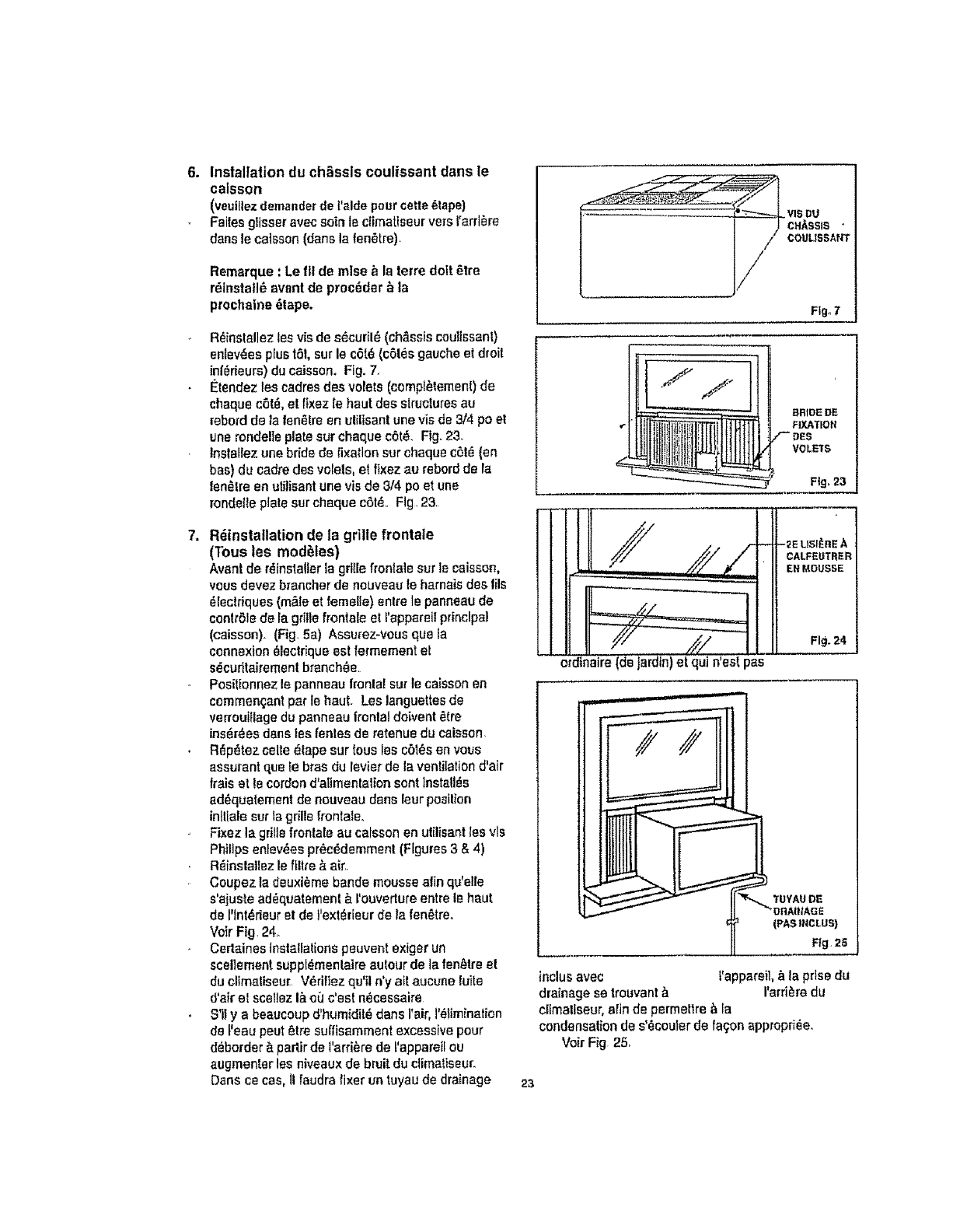
6. Inslallation du chassis coulissant dans le
caisson
(veutllezdemanderde I'alde poureerie _tape)
Faitesglisser avec soin le ciimatiseur vers t'arri_re
dens le caisson (dans la ten_tre).
Remarque : Le ftl de mlss _ la terra doit _tre
rdinstatl6 event de procdder _ la
prochaine _tape.
R_installez Iss vie de s_curil_ (chassis coulissanl)
sniev_es plus t6l, sur le c6[_ (c61_sgauche et droll
in|_rieurs)du caisson, Fig. 7.
I_tendez tee cadres des resets (cemp_lement) de
cheque c6t_, et fixez le haut dss structures au
rebo/d de la fend,Ire en ulilisant une vis de 3/4 poet
une rondelte plate our cheque c6t_.. Fig. 23.
Installezune bride de fixationsur chaqus c6l_ ten
bas) du cadre des volets, et fixez au rebordde la
fan,Ire en uliIisant une vis de 314poet une
rondelte piate sur cheque c6t_.. Fig. 23.
7. Rdtnstallation de la grille fronlale
(Tous lee mod_les)
Avant de r_instatler la grille frontals sur le caisson,
vous dsvez brancher de nouveau le harnais des tils
_Iectriques (m_le et femeIte) Shire le panneau de
contrSle de la grille frontals et I'appareilprincipal
(caisson). (Fig. 5a) Assurez-veus qua ta
connexion _lectrique est lermement et
sdcufltairemenl branch_s.
Posittennez le pannsau Iranla[ stir le caisson en
commengantpar le haul. Los languettes de
verroutflage du pannsau fronlaJdoivent _.(re
ins_r_es dens tss fentes ds retenus du caisson.
R_p_tez celte _tape sur tous les cbl_s en vous
assurant qus Ie bras du levier de la ventilation d'air
frets et Is cordond'a[Imenlalion sent lnsta!l_s
ad_quatement de nouveau dens leur position
inlliale sur la grills frontals,
Fixez la grille frontale au caisson en utilisant lee vls
Philtpsenlev_espr_c_demmenl (Figures 3 & 4)
R_inslaltsz le ftltre & ah'.
Coupez la deuxi_me bands mousse alin qu'elle
s'ajuste ad_quatement & rouverture entre le haul
de I'lnt_rieur el de t'ext_rieurde la fen_treo
Voir Fig. 24.
Certaines Inslallations peuvent exiger un
scellement suppl_menlaire autour de la fsn_trs el
du climatiseur. V_rifiez qu'il n'y sit aucune fuite
5'air el scellez i_ o_ c'est n_csssaire
S'il y a beattcoup d'hum(dR_dane I'air,]'_lim_nation
de ['eau pout _tre suffisamment excessive pour
d_border _ padir de l'arri_rede ['appareilou
augmenter les niveaux de bruit du ctimatiseur.
Dens cecas, II faudra fixer un tuyau de drainage 23
/
Fig.7
eRaSE DE
FIXA_ON
VOLETS
FI 9, 23
ordinaire (de jardtn)et qui n'esf pas
-_ELtSI_nEA
CALFEUTRER
EN MOUSSE
Fig, 24
¥UYAU DE
(PAStNCLUS)
Fig, 25
indus avec t'appareil,_la prise du
drainage se trouvant_ I'arfi_re du
ctimetlseur,afin ds permeltre _ la
condensation de s'_couler de fa_;oneppropri_e.
Voir Fig 25.
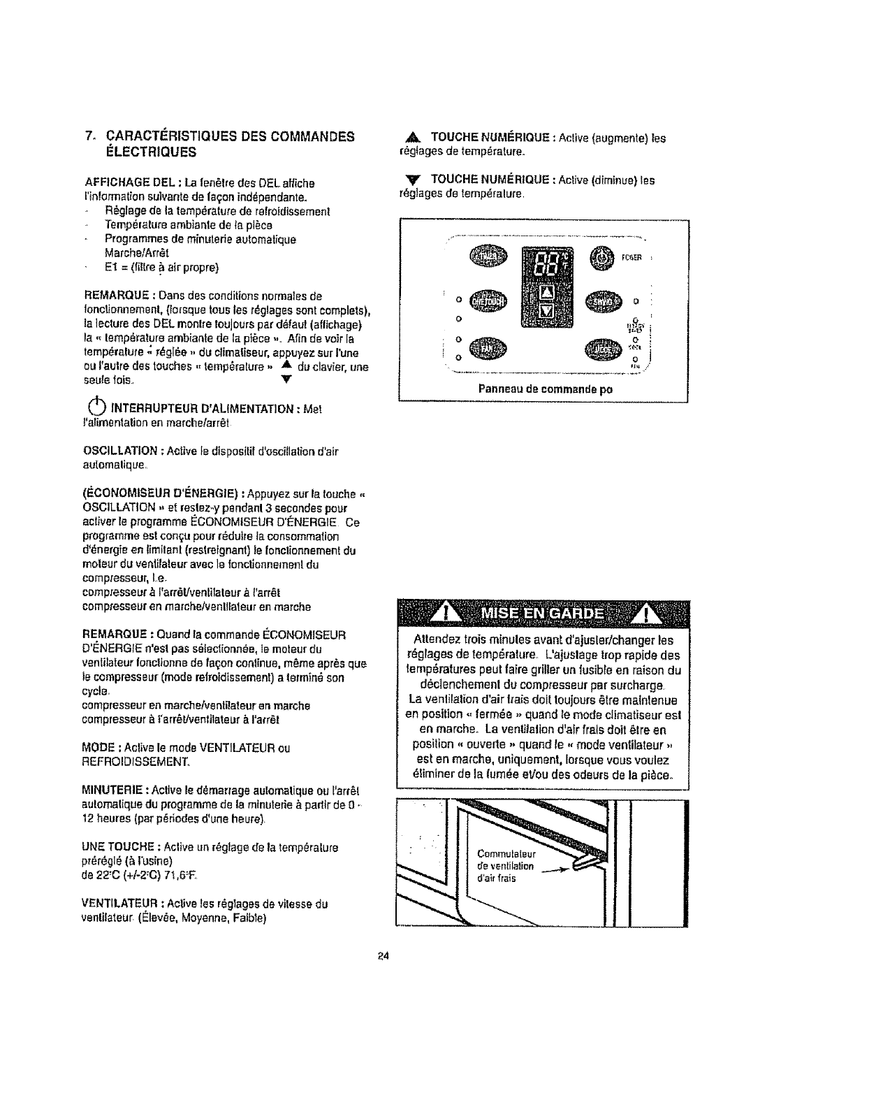
7. CARACT,eRISTIQUES DES COMMANDES
I_LECTRIQUES
AFFICHAGE DEL : La len_lre des DEL aNiche
rirt!ormation su]vante de faqon ind_pendante.
R_glage de la temperature de refroidlssemenl
Temperature ambianle de Ie pl_ce
Programmes de minutede autometique
MarchelArr_t
E1 = (|gtre _ air propre)
REMARQUE : Dens des conditionsnormatesde
lonctionnement, (Io_squetousles rdglages sent complets),
ta ]ecturedes DEL monlre touJourepar d_faul (afltchage)
la - lemp_rature ambiante de 1_pt_ce -.. Afin de veir la
temp_ralu_'e,; r_gl6e ,, du ctimatiseur,appuyez sur rune
ouI'aulre des touches ,, temp_ralure. A duclavier, une
seulelois. V
OINTERRUPTEUR D'ALIMENTAT1ON: Met
l'alimentation en marchelarr6t
OSCILLATION ; Active ledtsposttif d'oscillation d'air
automaliq ue•
(IECONOMISEUR D'ENERGIE) :Appuyez surts touche ,,
OSCILLATION ,, et reslez-y pendant 3 secondes pour
aclNerle programme I_CONOMISEUR D'ENERGIE Ca
programme est cen_u pour rddutre ia consommation
d'_nergie en limilant (res'.reignant) is fenclionnement du
moleur du veni.ilateur avec ]e fonctlonnemen! du
compresseur, I.e
compresseut' ,_ {'arr_lfventilaleur &{'errS|
compresseur en merche/venllfateur en marche
REMARQUE :Quand la commando I_CONOMISEUR
D'ENERGtE n'esl pas sSlectionn_e, te me|our du
venIitateur tor=cilonne de lab;on continue, m_me apr,_s qua
te compresseur (mode retroidtssement) a termin_ son
cycle.
compresseur en marche/ventilateur en marche
campresseur ._|'arr_l/ven|tlateur & I'atr_t
MODE :Aolive le mode VENT]LATElJR ou
REFROIDISSEMENTo
MINUTERIE : Aclive le demar_age automalique ou I'arr6f
automalique du programme de la mtnuterie _ partlr de 0 -
12 heures (par p_dodes d'une heure).
UNE TOUCHE :Active un r_gtage de ta temperature
pr_r_gl_ (_ t_usine}
de 22:C (+h2:C) 71,6_F
VENTILATEUR :Active |as r_glagesde vilessedu
venlilateur (E_lev,_e,Moyenne, Falble)
ATOUCHE NUMERIQUE : Acltve (augmente) los
r_giages de temp_.rature.
_lr TOUCHE NUMERIQUE : Active (diminue) lee
r_glages de temp_ralure,
Panneau de commende po
Attendez troisminutes evanS,d'ajusledchanger lee
r_glages de temperature. Uajuslage trop rapide des
tempSratures pout faire grilter ua lusible en raison du
d6ctenchemenl du compresseur par surcharge
La venlila|ion d'air I_'a_sdolt toujours*_t_'emainlenue
en position ,, ferm_e ,, quand remode climatiseur esl
en marche. La ventilation d'alr frals dolt _lre en
position ,, ouverte,, quand te ,, mode venfilateur ,,
est en marche, uniquemenl, lorsque vous voulez
_liminer de la lum_e eVou des odeurs de la pi_ceo
I
i
[
24
ALtMENTATION : Appuyez sur ta touche num0rique
ALIMENTATION pour met|re t'appareit en marche ou
I'arr6tero
ARI_GLAGES DE TEMPt_RATURE : Appuyez sur la
Iouche _,vers le haut ,, pour augmenter la temperature
r_g_e du cllmatiseur Cheque lois que vous appuyez
sur cette touche num_dque, Ia lemp_[ature est
augment_e comme suit:
2=F(_ohe!le Fahrenheit) R_glage maximum 90_F
I=0 (_chelle Ceisius) R_glage maximum 31°C
yRI_GLAGES DE TEMPI_RATURE : Appuyez sur la
touche ,, vers le bee ,, pour diminuer la tamp_ralure
r_gt_edu climaliseur Cheque tots que vous appuyez
sur cette touche num_r_que, ia temperature est diminu_
commesuit :
2'F (_chelle Fahrenheit) R_gtage maximum 60_F
t'0 (_chelle Cetsius) R_gtage maximum 16=C
OSCILLATION :Appuyez sur la touchenum_dque
OSCILLATION pour acliver Ia Ionctiond'osciltallon
automattque de I'air. La )umi_.repilote vede adjacente
la touche num_rique OSCILLATION s'aliumera,
Iden_lflantle made choisiqui est en marche. Los vole[s
vedicaux osci|terent en mouvements de va.eFvient
(d'un c51_,_ ]_autre)aulomaffquemento dfetribuant de
l_airaiternativemenl pourdonner un refroidissement
coniortabie Pour arr_,terle mode oscillatlon, appuyez
de nouveau sur la touche num_dque OSCILLATION, la
lumt_repilete vede adjacente _ la touche num_rique
s'6_.eindra..
(I_CONOMISEUR D'I_NERGIE) : Pour aoliver le mode
I_CONOMISEUR D'I_NERGiE, appwez sur la touche
num_dque - OSCILLATION ,, et restez-y pendanl 3
secondes. La i'umi_re pilote vede situ_e directement
au-dessus du mode _CONOMISEUR D ENERGIE
s'allumera identilIantle mode cho[siqul est en marche-
Le programmeI_CONOMISEUR D I_NERGIE side _,
r_duireta consomme|iond*,_,nergie(_lect_icff6) en
contr6lant (tim|tan|) le fonctionnement du moteur du
venti_ateur avec los cycles op_rationne!e du
compresseur,i,a
compresseur,_I'arr_liventilateur _ |'arr_t
compresseur en marche/ventilateur en marche
Si temode _CONOMISEUR D'ENERGIE n'est pas
active, le venlitataurIoncltonnerade talon continue,
m_me apr_s que le compresseur aura lini son cycle,
l.e. compresseuren marchetvenlilateur en marche
compresseur _ rarr_t(ventilateur en marche
REMARQUE : L'_conomiseur d*_nergle foncttonne en
mode ,, refroldtssemenl ,, seulemenL
MODE : Appuyez sur cette touchenum_dque pour
choisir te mode de tenor|on appropri_..
(Venli/ateudRefroidissement) Cheque p_essionsur la
touche MODE va altemer entre le mode ,,
REFROIDISSEMENT ,oet ,, VENTfLATEUR ,,. La
lumi_e pffote verle adjacente direolement ao-dessus
du mode REFROIDISSEMENT ou VENTILATEUR
s'illuminera, tdentiiianlle mode choisiquI est en
marche.
MINUTERIE : Appuyez sur cette touchenum_rlque
pouraotiver los programrnes, d_marrage automatique
,, et ,, arr_t automatique -de la minuterie. Les
programmee d_marrage/arr_.t automatiquespeuvent
_tre r_gi_s _.padir de 0-12 heures Cheque press|on
sur la Iouche num_rlqua de la MINUTERIE augmenlera
le temps choisi par p_riodes d'une heure chacune
DF_MARRAGEAUTOMATIQUE : Avant d'activer le
programme,, d_mar_age automalique ,,. vous devez
toutdabord chotstr(r_gter) tes conditions d
Ionctionnement du climaliseur (i,e, r_glaga de ]a
temperature, vitesse duventtlaleur,oscillation,etc,).
Lorsque tes r_glages sent compl_|_, le climatiseurdolt
_lre mls _ la positionarr_l tie pas en mode de
fonclionnement) Appuyez sur Is Iouche num_rique
M_,NUTERIE_t _'heurede d_marrage automatique
apparaTl_adens i'afftchage DEL, puts choislssez rheure
d_eir_e (0-12 heures), et Ie climatiseurva d6marrer
automatiquemsnt _ rheu_e_r_d_qu_e,
ARR_-TAUTOMATIQUE : Mettez le ctimatiseur en
marche et s_lect_onnez tes o_ndttlons requises de
fonctionnemenl (Le. |e r_glage de temperature el la
vitesse du venlilateur). Appuyez sur la touche
num_rique MINUTERIE et |'heoreeppara_tra dane
l'affichageDEL, seleclionnez I'heure d'arr_t
eutomaltqued_s]r_e (0 - 12 heures), et la clima!_seur
s'arr_tera automatiquemenl & i'heure d_termin_e.
REMARQUE : II n*est pa_ possible de faire fonctlonner
la lois te ,, d_marrage automa|ique ,, el r, arrt_!
automatique ,, clans un sou! programme. Teue lee
programmee& mtnuterie automalique sent
automatiquemenl effaces apree que le programm_
r_gl_ est compt_._
UNE TOUCHE ; Appuyez sur celte touche pouracttver
un r_glage de temperature p_,J'_gl_e& I'usine de 22'C
+1-2=C(71,6=F). Le cltmaliseurIonctionnera el
main|tundra la temp_ralura lnl_rieure _.ce r_glage.
Lee r_gtages de vitesee du venli|ateur peuven! aussi
_tre changes durant le programmeUNE TOUCHE.
25
l_Jj_lll={![_i[o]ll.l!_J_=,_l_tie}l I _ it=!,_iRl.lnJii=l Information sur [eflltre _ air
VENTILATEUR ; Appuyez sur cello touche pour actlver
re r_glage de vitesse appropri_e duvenlilateul:,
Chaque preseion sur Ia touchehumOr!qua va atlemer
les options de vitesse du ventt[ateur,Elev_e, Moyenne,
Faible., La lumi_re pitote vede correspondent _ i'oplion
de vitesse du VENTtLATEUR s'iiluminera et idenliliera
le choixeffeclu_
E1 = NETTOYEZ LE FILTRE ,&.AIR :Un message-
guide ,_E1 ,, s'affiehera automatiquementdens la
len6tre DEL indiquant le momenl appropri6 de natloyer
le filtre _ air Le programme E1 est un dispositifde
minuteria (encastr6) qui marche _.padlr de la dur6e de
lonctionnemen! (climatlseur). t] est tr_s Important de
toujoursgarder la fiitre _ air p[opre atin de maxtmiser
Pe|ficacit_ du refroldissement, (Voir Neltoyage du flltre
_.el0 Le filtre & air -dotl ,, absolumant 61reneUoy_
Iorsque le message ,, E1 ,, apparaiL Pour annular
(_liminer) _emessage E1 de l'affichageDEL, ]e
c[imatiseur, doit ,, 6tre d_b[anch6 (de la prise murals)
de la source d'alimenlation, puts rebranch6, Cola r6gle
de nouveau et automatiquemenl le dispositifinterne de
mlnuteda du programme ,, E1 ,,o
REMARQUE : Comma en cas de panne d'_lectricil_ }e
programme -E1 ,, est automatiquemenl remis on
lonctlon, nous vous sugg_rons d'enlever etde nelloyer
le _lre ,_air avanl Is red_marrage de I'appareiL
Affichage de la temperature Celsius/FAHRENHEIT ;
11as! possiblede changer I'affichege DEL de ta
temp_ralure en ,, Celsius ,, ou - Fahrenheit ,,, en
appuyant sur los touches num_flques (lemp_rature),
s[multan_ment.
La lurni_re pilate yetis. =C/'F ,, (symbols}s'aliumera,
tdenlifiantafnsi la s_Iection du mode_
Avant de preceder _I'entretiendu climatiseur, assurez-
vous de maitre ]e ctfmeliseur #.la position ,, ARRET ,,
et de d_brancher Ie cordon d'alimantalionde ta prise
_lectrique,
Le ti]fre &air joue un r0le lr_s impodant dane _es
niveaux do fonclionnemenl de lout climaliseur. Un ftllre
air propre rnaxlmisera !'efftcacit8 du refroidissemenl.
Un tillre _ air sale mintmisera refficactl_ du
_efroidfseement. II est doric important de garder le liltre
air ,, propre, en lout temps Col appare_ fail partie
d'un p_ogramme qui montrera un message. Et ,, (=
NETTOYEZ LE FILTRE A AIR) darts l'afliohage DEL
indiquanl quand ilest temps de nattoyer te filtre_ air,.
Enl_vement du flltre & air
Le tiltre _ air est silu_ derriere Jagrille frontalede prise
d'air. Pour enlever le filtre &air, saistssez la poign_e du
fiflre situ_e sur le devant de la gtilte at laites.,le gllsser
dreileo
Pour r_insteiler le flitre _ air, inversez los _tapes ci-
dessus,
Netloyage du filtre _air
1. Llti|tsezun asptraleur ,').poussieremunl d'une
brossa deuce pour or|lever los grosses salet_e.
Lavez le fillre dens de l'eau tilde de rosins de
40"_C(104=F). Sile tillra est tr_s sale, lavez-la
avec de I'eau savonneuse ou an agent nffttoyanl
neulre,, (NE LAVEZ JAMA|S LE FILTRE A AIR AU
LAVE-VAISSELLE).
N'uUltsez pas de nettoyants chimiquas torts pour
netloyer le ftltre_air,car ilspeuvent endommager
le plaslique et los rnailtes du lillre_
3. Rincez le filtreayes de i'eau propre et s_chez-ta
fond event de le r_installer.
Ne faites JAMAIS |onctionnerle cllmatiseursans le
fillre&air, car les particules de poussi_re peuvent
provoquer la d_lailtance de i'_quipement.
2_
3-
N'utilieez PAS de l'essence, un produil chimtque,
diluent ou autre sur un climatlseur, car cos
substances peuvent endommager [a ftnilion de la
peinlure et d_former des pi_ces en plastique.
N'essayez jamais de verser de l'eau direclemenl
sur le climatiseur,car cola provoque une
det_rioration de I'isolation _tectrique_
Lorsque la grille d'entr_e d'air et le caisson sent
sales, los taver _ I'eau ti6de, (eu-dessous de 4O'C
(104_F)_ S'its sent tr_s sales, los laver avec de
f'eau savonneuse ou un agent nelloyar_t neu_re
Entretien hers satson
I. Faitss fenc_ionneruniquement le ventilateur
(vilesse _tev_e) pendant une demi-joum_e pour
s_cher I'int_rtaur du climatiseur.,
2. Toumez rinterrup_eurd'ailmentation _.ta position
arr_t et d_branchez la fiche de la prise mutate.
3, Netloyez le filtre _ air el le caisson e_!_rieuro
4 Rangez le climaliseur {couvert) dans un endroil sac.
26
- -- =[_it,J=hJ==Dm'J._Bir_%_l_=
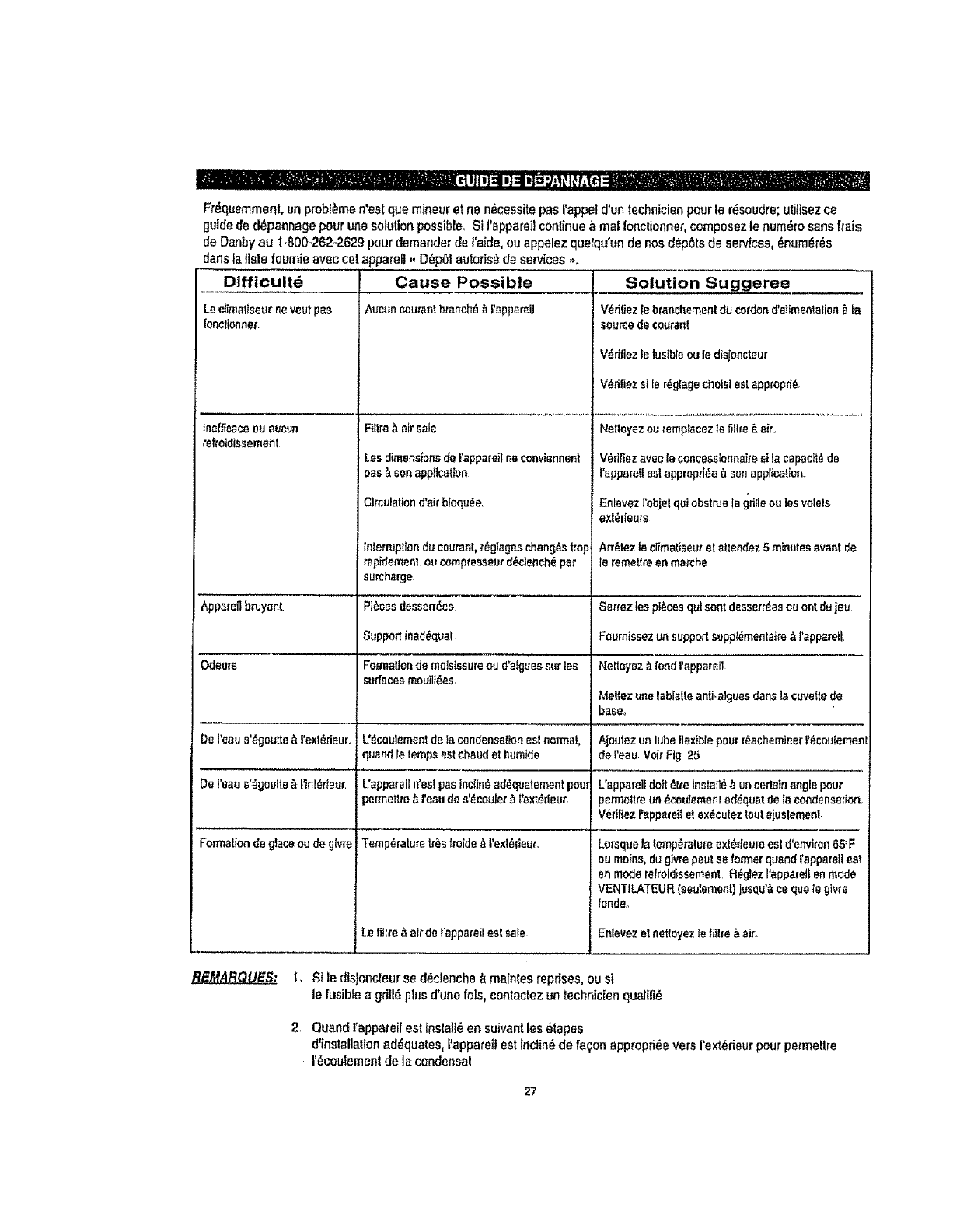
Fr_quemmenl, un problems n'est qua mineur el ne n_cessite pas rappet d'un technicien pour le r_soudm; utitisez ce
guide de d_pannage pour une solution possible_ St I'appareil conlinue ,_ real Ionctionner, cornposez le num_ro sans frets
de Danby au 1-800.262-2629 pour demander de t'aide, ou appefez quelqu'un de nos d_pets de services, _num_r_s
dens la lisle foumie avec col apparell - D_pel aulods_ de services ,,.
Dtfficult_ Cause Possible
Aucun coumntbranch_ _ rsppamllLBclimatiseurne vsut pas
I'encflonner.
Insflioaceou sueun
_efroldlssement.
Apparellbruyant
C}_eu_s
De reeu s'_goutte _ t'extedeun
De reau s'_goulte _,t_nt_rteur.
Formation de gleesou de givre
Fllfm_ air sale
Lssdimensions del'appareil na convisnnent
_es_ son appltcatlen
3tmulationd'air blodu_e,.
lnlenUplion du coarser,regtagss chang{_strap
rapidemenl,ou compresseard_clench,_ pat
surcharge
=]_cssdesssn_ss
Support inad_qual
Fomtatlon de molstssure ou d'alguss sur los
sud_cesmouilf#.ee.
L°_aulemen! de Ia condensalioneel normal,
quand letemps eatcheudel humide
!'apparell n'eetpas Inciin_ad_quatement poem
Jsmlettte _ I'eau de a'_eouler_,f'ext_deut.
Temperature tf_sltsidsA t'ext_fieur.
Le lit[re A alrde !'apparsBeat sale
Solution Suggeree
V_dliez le branchemenl du cordond'altmentatisnAla
GOUF(;Bde Goararl(
V_rillez le fusibleoule disjencteur
V_dfiez sl Is r_glage choisieelapprepd_,
Neltsyez eu remplacez Is firm & air,
Vedtiezavecleconeesslonnai_eeila capaclt_de
_'appareIIsslapprspd_aa senapplication.,
Eelsvez l'objst qui obstrus la grillseu leevalois
exf_ieare
An_tez Is climaliseurel altendez 5minutes avant de
lersmet_resn marche
Setmz leepI_ces quIsent desserr_es eu oat du ieu
Faumissez un supportsupp!_mentaire _ t'appsmll,
Neltm]sz _.fondrsppareil
Mellez use lablstle anti.,alguesdane la cuvettede
bass,
Ajoutsz un tube flexible pour[_acheminer t'_eoulemenl
de _'eau.Voir Fig 25
L'appareiideft _{te tnstall6 ,_ uacedainangle pour
_ermelfreun _ceutemen! ad_quat de le condensation.
V_rfftez I'appa{eil st sx_cutez tout ajuslemeet
Lemque la temp_}ratureext_=ieumeat d'environ65=F
eu means,du glvrepeut ss fem_erquand [apparstl eat
en mode relroidissemenL R_glez I'appamll anmode
VENTILATEUR (sautement) jusqu'A ce qua tegtvre
fends,,
Enlevezet nstloysz Isfiil_e_ air.
RE/ffAR_ 1. Sile disjonc_eurse d_clenche _ mainles reprises, ou st
le fusiblea g_itl_plus d'une lots, contaetezun technician qualilid
2. Quand [appareil est Install_ en suivant lee _tapes
d'instalialion addquatee, t'apparetlest Inclindde fa_o_ approp_e vers rext_.rieurpour pe_meUre
I'_cout_menl de la cendensal
27
GARANTIE LIMITI_E DE CLIMATISEUR
_l _t:_aleildequ_'_eelg_rBnt'_e_emp]de'_utviced_rr_a_i_p_rr_l_raeId_!_br_n, s]les!u_l_ d_%leeo_ndilio__ales le_s _(
Gelfeguan_ede_to((_Jle(t'd,_Facha_urir_=j del'ap_ae_i]ue_u p._lDanbI,'oup_rFundess_.ff3t,';boteursag.'_sel e_ene_ul _l_e((_(',_ktl_e
COHDlllOh!S
EXCLUSIO)18
En_u de(a_nle, irn'e_(_auc_meautr_ger_nlle,co_il(_ou_0(_senle_ic,n,q_'ellesexe_pri_'_e_ ladle.,_ la_nmafffesleouInt_-nt(_nello.(_'
Dar,b'!P_'od_cisU_il_.(Canada)ouD_nb)*P_od_dslac(E-UgA )oueesdistObul._urseg(_s.Dem_me,s(m{_xduesloul_I_a_esgm'enU_.(mnd)tbn_
(7.,repl_e__lalio_yc.t_'n0Hsle.s(j_(ant_e.s,con,:fi:ic_sou_pf_senlai_o_enVide_ loule(_ir_]ss_llaVentedep(_uils_ deiouteaul,'e16g_lalioeou
r_len',en!sembl_L_es.
En\,erludel_pr_enle._'b),_oducleUn',il_e(Canade)ouDanbyPre,'J_.tsIr_(Eo-U d'A)_ pe_Aim!_ue(_nsab[e_ ca..s_ ble_u(es(>ofo'Jre,'l_ou
0esd_g)IsmalG(iels,y_rF,p,';s_f_ppu_],quel_equ'enso)ll_sceuses.Oa_bynepe_tp_Ifelenue(espor_BbIe{lee_bmmagesln_(_ls@sau
lonclionn.emer,ld_!ec_uxdel'_0pa(e((Enech_l_lf_(_p_reil,Fachel_rBccemol_demeltm(_coJcer_elde0_ge( DenbyP(_u_ Um)_ deice
re_pen))bilit6enC_LSde(_clarneUon_i(rlouleblessuleco_re((eoutoutd_t m_l_H_Ic.Ius_)p,!(_lepF,_Je_
COllOlItON)G(NEBALEB
L_g_an)_ouassuranced-:(eSsuln_e'app(_i(_p_ slleed_0_lsour_ps(eU_ss_I((usa.uxcas_)'_a_ts:.
I) Pznr,edeco,_'_l;
)) Dc_vneg_subispendantlel(_nsportouled_F,'_cen's_nIdefapp_(_l;
3) A_(r'_t_n_e_(_q_:_-.mc_ec_tens_n_a_b_e_c_b_e_ed6te_(_e_J_fus(_es_n_((ecL_);
4) A_d_nl, r_odif_ca_on,entp_ol_L_c,,Jbco((eclOel'_F_,eil;
5) UIi(isaliondane_ b_lco_mercialmJindusbie(;
6) _n_enrj_e_mm)_ec_u_p_re_2_gue(_e_rneu_e_ho:.f_s_c_sde_ceme_eu(e(_g_n_a_e_¢_)_
7) V(s``4es(i_ech_'_Ii_enp_u_ex_:q_e_`.j_e_i_nr,emer_r_e_F.p_e(lBup(_p(_alm
Ur_pr_;,ed_ch_tdeil_l_ep;_sen(_u_louted_n',_ndede_Z,paf_f,onsou,sg.=r_niePd_(ede_erlere_u,Poul((_i_ehonorerl_{g_an_e,pf_nle_ce
doc_:menl_ las_t_lech_iq,_Bgi_eeus'ed(_sl(0:
ISe_)cesous._afz=rdie
CllmelleeurCened(_ E,-Uod'A
Dernic)eD)mic)!_r
D_b)" p(odud; Llmlled O(nbk_l:Yode(loInc.
PO Box I'T/0._70 "_l'_e)owIll),Guelph.On!etlo_Cenedo Hill_ PO Box _e, iel E_n_y Coud, Rnd(ay,Ohlo,U SJ.. 458..I0
Telephone: (_|g)(_]?.o'g_FAX: (51g)83.7_44) Ot¢o! '#elepl'_'te: {4!S}42_-8621FAX: (,_ig)()..,_._J4_
mar.ay
Model*Mod_te
DAC7024DE
Forser_ce,contactyogr_earest
servtcadepotorcall:
1-800-263-2629
PourobtenirIs service,consullsz
vo_esuccursalar_gbnalede
serviceout_t_phonez:
1-800-263-2629
Room Air Conditioner
The model number of your room air condilIoner Is found on the serial
pla_e located on the right side of the unit above _he power cord
A|t repair pads are available for purchase or special order when you
visit your nearest service depot, To request service andlor the
location of the service depol nearest you. call the TOLL FREE
NUMBER: 1-800-263-2629
When requesting service or ordering pads. always provide the
Iollowing informalion:
• Product Type
• Model Number
,, Part Number
•Part Description
Climatlseur de pl_ce
Le num_ro de rnod_Fe de votre climatiseur se trouve sur la plaque
d'Informatton qui se trouve sur re cot6 droil de t'eppareil par dessus te
cordon d'a{imentation.
Toutes les pi_ces de rech_nge ou commandes sp_ciales sent
d_sponibles de votre centre r_g_onal de service autoris_.. Pour ex_ger
le service el-ou le nom de votre centre de service r_gionst, s_gnafez le
NUM(_RO SANS FRAIS: 1.,800-263-2629
Ayez lea renseignernents suivan|s _ la portia de le main tors de ;a
commande de piece ou service:
. Genre de produit
. Num6ro de mod_te
• Num_ro de p_ce
• Description de la pl_ce
DanbyProduclsLimited,Guelph,OntarioCanadaN1H6Zg
DanbyProduclslnc,,FindIay,OhioUSA45840
Pdr,t_l in C_n_ (P R.C )
