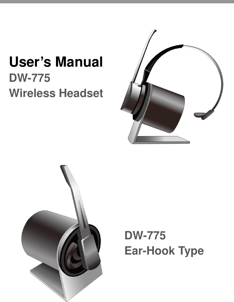
DASAN ELECTRON DW-775B WIRELESS HEADSET (FIXED PART) User Manual Anti virus enging is built in inside main board

DASAN ELECTRON WIRELESS HEADSET (FIXED PART) Anti virus enging is built in inside main board

Users Manual

                                                    User’s Manual DW-775 Wireless Headset DW-775 Ear-Hook Type
CONTENTS  1  Introduction 2  Features – headset and base unit 3  Features – base unit back 4  Setting up the unit 5  Battery Charging 6  Operation -  Pairing your Headset and Base Unit -  Checking for compatibility -  Making and ending a call using a telephone with Lifter attached -  Answering a call using a telephone with Lifter attached -  Adjusting the TX(transmit) volume -  Adjusting the RX(receive) volume -  Muting the microphone on the headset -  VoIP with PC(Optional) -  Using multi-headsets -  De-registering all headsets -  Electronic Hook Switch 7  Replacing the battery 8  Technical features 9  Optional accessories
 INTRODUCTION  Thank you for purchasing this product  The unit has been developed using the latest wireless technology. With the unit we  are  confident you will experience  a great level  of  comfort  and  freedom compared to using a standard telephone for making and receiving your calls.  READ THE USER GUIDE  The unit is very easy to use and set-up, although to get the best from your new purchase, we recommend you read this User Guide before getting down to any calls.  UNPACKING  Remove the unit from its packaging and ensure that along with this User Guide you have the  correct  mains  plug  fitted  to  the  power  supply  unit  for  your  supply  and  the  correct specified accessories.  Retain the packing carton for storage of your unit, and also in the unlikely event that the unit needs to be returned for service or repair.  IMPORTANT Ensure  that  all  electrical  connections  (including  extension  leads  and  interconnections between  pieces  of  equipment)  are  properly  made  and  in  accordance  with  the  relevant manufacturers instructions.  1.  INTRODUCTION
 Do not continue to operate the equipment if you are in any doubt about it working normally, or if it is damaged in any way.   Switch off, withdraw the mains plug and consult your dealer.  Do not allow electrical equipment to be exposed to rain or moisture.  Never  push  anything  into  holes,  slots  or  any  other  opening  as  this  could  result  in  fatal electrical shock.  Never guess or take chances with electrical equipment.  Do not open the telephone housing as doing so will void your warranty.  WARNING Telephone headsets are capable of producing high levels of sound. Prolonged exposure to high sound levels can cause damage to hearing.
    -  Ear-Hook        2.  Feature – Base and Headset Unit CALL On/Off  RX volume/Mute / Pairing   IN-USE    Charging LEDs  Microphone IN-USE LED  PC Selection S/W  TEL Selection  Pairing    Mute LED
-  Plastic Band & Headset Holder                                                          3.  Feature – Base Unit Back
   Despite  the  sophistication  behind  the  unit,  the  set-up  and  operation  of  the  unit  is remarkably  simple.  Please  follow  these  steps  in  the  following  pages  and  refer  to  the drawings  on  the  previous pages and you will be  up  and  running  with  your  new  wireless headset in a very short time.  Important: Before first use, please charge the headset fully  for  up to  2~3 hours to maximize your battery operational life.   1   Connect the TELEPHONE HANDSET TO THE UNIT Unplug  the  handset  cord  from  your  telephone  base  unit  and  plug  it  into  the HANDSET port located on the back of unit.   2   Connect the TELEPHONE BASE UNIT TO THE UNIT Use  the supplied telephone cord and connect  on  end  to  the HANDSET port on your telephone base unit. The other end should be connected to the TELEPHONE port located on the back of the unit.   3   Connect the POWER SUPPLY UNIT Plug the Power Supply Unit to the DC Input Jack on the back of the unit. Then connect the Power Supply Unit to your wall supply.   4. Setting up the Unit
 4   Place the headset on the base unit to charge    Important: Before first use, please charge the headset fully  for  up to  2~3 hours to maximize your battery operational life.   !   Place the headset on the base unit to charge Always place the headset on the base unit when not in use to allow your headset to be charged and ensure the talk-time and life of the battery.  Before first use, please charge the headset fully for up to 2~3 hours to maximize your battery operational life.  Only use  the  base  unit fitted with the original  power  supply unit  to  charge your headset, or damaged and incorrect operation may occur.  When  charging  the  LEDs  on  the  front  of  the  base  unit  will  illuminate  in  WHITE.  The following are the status and colors expected during the charging process.  Charging Status LEDs status(BASE) Charged status Charged status with 3 white LEDs Charging Indicator light will flash while charging Full Charged 3 while LEDs are blinking at the same time   5. Battery Charging
  Before operation your headset must be paired with your base unit, this can be confirmed by the following check:   After  power  on  the  Base  and  Headset  unit,  it  takes  5  seconds  to  be  paired automatically. If your headset unit LED is constantly blinking, you need to pair your headset with your base unit.  Headset Action Audio indicator Low battery 2 rapid beeps + 20 second pause Volume up/down 1 quick beep Volume max/min reached 3 beeps Incoming call with LIFTER melody Telephone line (open/close) 1 beep Headset out of range 1 beep + 10 second pause(repeats) Mute activation/deactivation 1 beep   Base Action Visual indicator Pairing Mode In-use LED is blinking fast TX Mute Mute LED(RED) is ON In use In-use LED is blinking slowly       6. Operation
 1   Power ON/OFF the headset 1.  Power OFF - Press and hold the ON/OFF button on the headset until RED LED is blinking twice. Release the button. 2.  Power  ON  -  Press  ON/OFF  button  on  the  headset  shortly  or  place  the headset on the Base unit.   2   Pairing your Headset and Base Unit 1.  Press and hold the pairing button on left side of the front panel of the Base unit about 2 seconds. Release the button.(RED LED is blinking faster) 2.  Press  and  hold the  mute  button  on  the headset  until  RED LED  is  blinking. Release the button.  Check the LED status when you push the ON/OFF button of headset.  BASE LED HEADSET LED IN USE Mode BLINKING OFF Stand-by Mode ON BLINKING every 10 seconds Not paired BLINKING OFF
 3   Checking for compatibility (Default Setup: ‘1’) As telephone manufactures can vary their configuration, it  is  necessary  to  have compatibility selections on the base unit to ensure that the unit is compatible with virtually any telephone.  To check  and adjust  for  compatibility between the  Base  unit  and  the  telephone perform the following:   While wearing the headset – push the ON/OFF button   If you cannot hear a dial tone with the factory setting, switch to the ‘2’ position of the COMPATIBILITY switch on back of the base unit until you hear a clear dial tone.   4   Making and ending call using a telephone with LIFTER attached   While wearing the headset, press the ON/OFF button   Check the lifter function activates (telephone connection opens)   You can hear a dial tone   RED LED on the headset unit will be turned off (in-use status) and RED LED on the Base unit is blinking.   Dial desired number   To end the call press the ON/OFF button on the headset   Check the lifter function de-activates (telephone connection closes)   RED LED on the headset will be blinking every 10 seconds (standard paired status) and RED LED on the Base turns on.
 5   Answering a call using a telephone with Lifter attached    The telephone rings   While wearing the headset, press the ON/OFF button on the headset   The lifter function activates (telephone connection opens)   To end the call press the ON/OFF button on the headset   The lifter function will de-activate (telephone connection closes)   6   Adjusting the TX (transmit) volume The TX (transmit) volume can be adjusted using the volume control located on the back of the base unit. Adjust the volume by pushing +/-  button to increase or decrease the level. The volume should be set to personal preference. To adjust follow these steps:   Make a telephone call and ask the person you are calling for their assistance.   Adjust the volume as you talk by pushing the volume control up(+) or down(-)   Ask the person you are calling to tell you when the volume of your voice is acceptable.   If  the  TX(transmit)  volume  is  still  low,  then  set  the  MICROPHONE SELECTION switch located on the back of the base unit to “B”
 7   Adjusting the RX (receive) volume Follow these steps:   Make a telephone call and ask the person you are calling for their assistance.   Adjust  the  RX  (receive)  volume  by  pressing  the  up/down  buttons  on  the headset while your caller is speaking.  8   Muting the microphone   To MUTE the microphone on the headset press the MUTE button located on the headset or In-use button located on the front of base unit.   To turn the MUTE off, press the MUTE button again.  Normal  operation  will now resume.  9   VoIP with PC (Optional)  DW-775 is optimized for Microsoft LYNC   Connect USB cable (option) between PC and mini USB port of Base.   To make call or receive through, push the PC/TEL button first and then press the ON/OFF button.   10   Using Multi-headset   6  Headset  can  be  registered  to  base  unit.  It  means  that  6  users  can  use headset with one base unit.   After being registered all headsets, all users can hear ring alert wile incoming call. User who pushes talk-button first can talk with caller.  ★ For using multi-headset, each headset is needed to be paired with base unit.
 11   De-registering all headsets   Unplug the power cord from the base unit..   While pushing TX buttons(+/-), plug the power cord into the base unit.   After 2~3 seconds, red LEDs will be ON.     Now, all registered headsets are cleared. Register headset you want to use.    12   Electronic Hook Switch (DASAN DHSG cable: accessory)  The unit enables you to answer  and  end  calls  remotely by using its built-in electronic  hook  switch  (EHS).  EHS  of  the  unit  is  only  possible  on  certain telephone systems supporting EHS.    ★ EHS is only possible on certain telephone systems. In order to determine  which telephones  have  the  EHS  feature  enabled,  please  refer  to  EHS  guide.  Please also refer to your telephone’s user manual for clarification.
   1   Replacing the battery     Ensure the headset is turned off   Take off the headset cover   Replace the battery  ★ Ask local distributor to replace the battery.                    7. Replacing the Battery
  Compatibility      Compatible with most standard corded desk phone Radio Frequency Range    Europe: 1.8GHz (DECT)         US: 1.9GHz (DECT) Radio Frequency Modulation    0.5 GFSK (Gaussian Frequency Shift Keying) Operating range      Up to 90 meter (Approx. 300 feet) Talk time       Up to 7 hours Standby time      Approx. 72 hours Battery type      Lithium Polymer Charging time      approximately 3 hours Power Supply Unit      Output Voltage: DC 9V 600mA                   8. Technical Features
   1   DL-570L Handset Lifter This handset lifter has been exclusively designed for use with the unit, allowing you to answer and end calls with the touch of a button when away from your desk. Features:   Remote one-touch answer/end of calls   Automatically lifts and replaces handset   Compatible with most standard telephones   Easy installation   2   EHS Adapter (Optional) EHS Compatibility Table Telephone Supported EHS EHS Adapter  SIEMENS OpenStage 40/60/80 POLYCOM IP330 SNOM Aastra DHSG DS-DHSG Cable  POLYCOM IP331 DHSG DS-DHSG-PLC  CISCO 7965G HHC DHHC Adapter  ALCATEL 4028 ALCATEL 4038 MSH DMSH Adapter  Avaya 9620 AEI DAEI Adapter  *Avaya another model AEI DAEI-II Adapter   9. Optional Accessories
 3   Other Accessories (Optional)              After finishing the connection, please tie all cables with a cable-tie.               USB Cable
  We will repair or replace, at our opinion, this product if found defective due to materials or workmanship within the warranty period beginning from the original date of purchase. This product is warranted by authorized representative for the period specified.  The Original dated purchase receipt  must be  presented to the authorized service center when service  is  rendered. On all carry-in models, transportation to and  from  the  service station is the responsibility of the purchaser.  This warranty does not cover damages due to accident, fire, flood, earthquake and/or other acts of God; misuse, incorrect line voltage, improper installation, improper or unauthorized repairs,  commercial  use  or  damages  occurred  in  shipping.  Exterior  and  interior  finish, lamps, glass, plastics parts and temperature probes are not covered under this warranty. Customer adjustment according to the owner’s manual are not covered under this warranty. This warranty is automatically void if the serial number is missing or altered.             Warranty and service
Bogota SIRCI Project  User Requirement Definition CB-EDR-HM-00-V1.0 Automatic Recharger Page62 of All FCC Statement  This device complies with Part 15 of the FCC Rules. Operation is subject to the following two conditions: (1) This device may not cause harmful interference. and   (2) This device must accept any interference received, including interference that may cause undesired operation.  Any changes or modifications to the equipment not expressly approved by the party responsible for compliance could void the user's authority to operate the equipment.    Note: This equipment has been tested and found to comply with the limits for a Class B digital device, pursuant to part 15 of the FCC Rules. These limits are designed to provide reasonable protection against harmful interference in a residential installation.   This equipment generates, uses and can radiate radio frequency energy and, if not installed and used in accordance with the instructions, may cause harmful interference to radio communications. However, there is no guarantee that interference will not occur in a particular installation. If this equipment does cause harmful interference to radio or television reception, which can be determined by turning the equipment off and on, the user is encouraged to try to correct the interference by one or more of the following measures: —Reorient or relocate the receiving antenna. —Increase the separation between the equipment and receiver. —Connect the equipment into an outlet on a circuit different from that to which the receiver is connected. —Consult the dealer or an experienced radio/TV technician for help.  .

Navigation menu