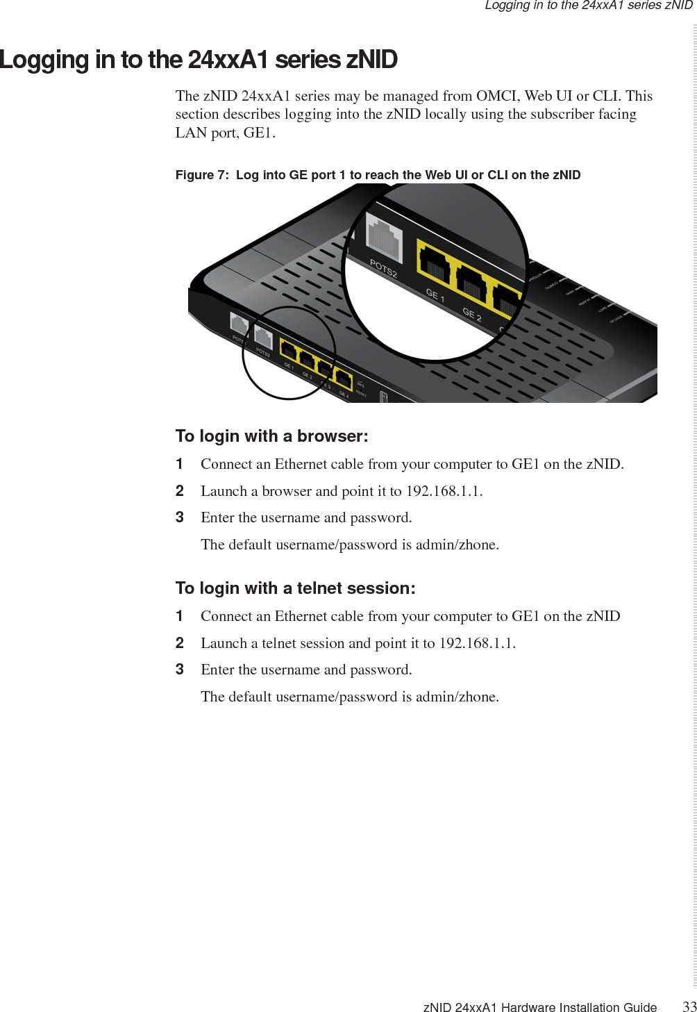
DASAN Zhone Solutions 2426Y1 (1) GPON 4 Port WiFi Gateway (2) GE 4 Port WiFi Gateway User Manual zNID 24xxA1 Series Hardware Installation Guide

DASAN Zhone Solutions, Inc. (1) GPON 4 Port WiFi Gateway (2) GE 4 Port WiFi Gateway zNID 24xxA1 Series Hardware Installation Guide

Users Manual

   zNID 24xxA1 SeriesHardware Installation GuideFor software version 4.xJanuary 2017Document Part Number: 830-04218-01
2zNID 24xxA1 Hardware Installation Guide   DASAN Zhone Solutions7195 Oakport StreetOakland, CA 94621USA510.777.7000www.zhone.cominfo@zhone.comCOPYRIGHT C2000-2017 DASAN Zhone Solutions, Inc. and its licensors. All rights reserved.This publication is protected by copyright law. No part of this publication may be copied or distributed, transmitted, transcribed, stored in a retrieval system, or translated into any human or computer language in any form or by any means, electronic, mechanical, magnetic, manual or otherwise, or disclosed to third parties without the express written permission from DASAN Zhone Solutions, Inc.Bitstorm, EtherXtend, IMACS, MALC, MXK, Raptor, SLMS, Z-Edge, Zhone, ZMS, zNID, MX, MXP, the DASAN Zhone Solutions logo and the Zhone logo are trademarks of DASAN Zhone Solutions, Inc.DASAN Zhone Solutions makes no representation or warranties with respect to the contents hereof and specifically disclaims any implied warranties of merchantability, non infringement, or fitness for a particular purpose. Further, DASAN Zhone Solutions reserves the right to revise this publication and to make changes from time to time in the contents hereof without obligation of DASAN Zhone Solutions to notify any person of such revision or changes.
zNID 24xxA1 Hardware Installation Guide 3TABLE OF CONTENTSAbout This Guide 5Style and notation conventions..............................................................................5Typographical conventions.......................................................................................6Related documentation.............................................................................................7Acronyms......................................................................................................................7Contacting Global Service and Support...............................................................8Important Safety Instructions..................................................................................9Laser Safety Instructions...........................................................................................9Instructions de sécurité relatives au laser................................................................10General Instructions................................................................................................11Instructions générales..............................................................................................12Compliance ................................................................................................................13FCC Statement........................................................................................................13FCC Radiation Exposure Statement.................................................................13Caution!............................................................................................................13CE ...........................................................................................................................14Canada Statement....................................................................................................15FCC - Part 68 ..........................................................................................................16REN (Ringer Equivalent Numbers) Statement ......................................................16REN Statement (Canada) .......................................................................................16Attachment Limitations Statement  ........................................................................16EMI Precautions......................................................................................................18Canada..............................................................................................................18Chapter 1 zNID 24xxA1 Series...............................................................................................19Overview  ....................................................................................................................19zNID 24xxA1 series components ...........................................................................21zNID 24xxA1 series features..................................................................................23zNID 24xxA1 models .............................................................................................23zNID 24xxA1 series specifications.........................................................................24zNID 24xxA1 series dimensions ............................................................................29zNID 24xxA1 series LEDs.......................................................................................30Logging in to the 24xxA1 series zNID.................................................................33
Table of Contents4zNID 24xxA1 Hardware Installation GuideChapter 2 zNID 24xxA1 Installation.....................................................................................35Install the zNID ..........................................................................................................35Installation precautions...........................................................................................37Mount the zNID......................................................................................................38Wall mount with fiber tray...............................................................................38Wall mount without fiber tray..........................................................................41Desktop with fiber tray.....................................................................................43Manage the optical cable  .......................................................................................44Fiber handling...................................................................................................44Testing optical power.......................................................................................44Optical fiber cable placement in the zNID fiber tray..............................................45Connect to network.................................................................................................46Connect power ........................................................................................................48Connecting phone terminals ...................................................................................49Connecting Ethernet ports.......................................................................................50Connecting USB port..............................................................................................51Complete the zNID installation ..............................................................................52Appendix A Appendix: Pinouts.................................................................................................53Gigabit Ethernet pinouts ........................................................................................54POTS pinouts.............................................................................................................55UPS pinouts ...............................................................................................................56Index......................................................................................................................................................57
zNID 24xxA1 Hardware Installation Guide 5ABOUT THIS GUIDEThis guide is intended for use by installation technicians, system administrators, or network administrators. It explains how to install the zNID 24xxA1 series enclosure, electronics and cabling. Style and notation conventionsThis document uses the following conventions to alert users to information that is instructional, warns of potential damage to system equipment or data, and warns of potential injury or death. Carefully read and follow the instructions included in this document.Caution: A caution alerts users to conditions or actions that could damage equipment or data.Précaution : Une mention Précaution avertit les utilisateurs au sujet d'états ou d'actions qui pourraient endommager le matériel ou les données.Note:  A note provides important supplemental or amplified information.Remarque : Une remarque fournit des informations supplémentaires ou amplifiées importantes.Tip: A tip provides additional information that enables users to more readily complete their tasks.Conseil : Un conseil fournit une information supplémentaire qui permet aux utilisateurs de réaliser leurs tâches plus facilement.WARNING! A warning alerts users to conditions or actions that could lead to injury or death.AVERTISSEMENT ! Un avertissement avertit les utilisateurs au sujet d'états ou d'actions qui pourraient entraîner des blessures voire la mort.
About This Guide6zNID 24xxA1 Hardware Installation GuideWARNING! A warning alerts users to conditions or actions that could lead to injury caused by a laser.AVERTISSEMENT ! Un avertissement avertit les utilisateurs au sujet d'états ou d'actions qui pourraient entraîner des blessures causées par un laser.WARNING! This icon warns the user that metal surfaces can become hot to touch. Avoid contact or use caution when touching these surfaces.AVERTISSEMENT ! Cette icône prévient l'utilisateur que les surfaces métalliques peuvent devenir chaudes au toucher. Evitez le contact ou soyez prudent lorsque vous touchez ces surfaces.Typographical conventionsThe following typographical styles are used in this guide to represent specific types of information. Bold Used for names of buttons, dialog boxes, icons, menus, profiles when placed in body text, and property pages (or sheets). Also used for commands, options, parameters in body text, and user input in body text.Fixed Used in code examples for computer output, file names, path names, and the contents of online files or directories.Fixed Bold Used in code examples for text typed by users.Fixed Bold ItalicUsed in code examples for variable text typed by users.Italic Used for book titles, chapter titles, file path names, notes in body text requiring special attention, section titles, emphasized terms, and variables.PLAIN UPPER CASE Used for environment variables.
Related documentation zNID 24xxA1 Hardware Installation Guide 7Related documentationRefer to the following publication for additional information:•zNID Quick Installation Instructions for the zNID you are installing. These instructions are shipped with the zNID, but are also available on the DZS website.•zNID RG Configuration Guide — explains how to use the zNID web interface and describes the system commands and parameters. Refer to the release notes for software installation information and for changes in features and functionality of the product (if any).AcronymsThe following acronyms are related to DZS products and may appear throughout this manual:Table 1:  Acronyms and their descriptionsAcronym DescriptionActive E Active Ethernet, also known as Gigabit EthernetAPC Angled physical contact (for fiber connector)Coax Coaxial cableCNI Comfort Noise InsertionCPE Consumer Premises EquipmentDHCP server Dynamic host configuration protocol serverEZ touch™ DZS’s implementation for managing CPEs and zNIDsGigE Gigabit EthernetGPON Gigabit passive optical networkHPNA  Home phone line networking allianceIPTV Internet protocol TVLED Light-emitting diodeMALC Multi-access line concentratorMDU Multiple Dwelling UnitMIB Management information basesMoCA Multimedia over Coax AllianceOLT Optical Line TerminatorONT Optical Network Terminator
About This Guide8zNID 24xxA1 Hardware Installation GuideContacting Global Service and SupportSupport for this product is provided by your Internet service providerONU Optical Network UnitPoE Power over EthernetPPPoE Point-to-point protocol over EthernetQoS Quality of serviceRF Radio FrequencyRFoG Radio Frequency over GlassSC adaptor Subscriber connector adaptorSIP Session initiation protocolSNMP Simple network management protocolT1/E1 T1 is Trunk line 1 (or DS 1, digital signal level 1). E1 is the European equivalent, though there are a number of differences between the North American T1 and the European E1.UPC Ultra physical contact (for fiber connector)Wi-Fi Wireless local area network (trademark of Wi-Fi alliance)VAD Voice Activity DetectionVOIP Voice over IPzNID Zhone Network Interface DeviceZMS Zhone Management SystemTable 1:  Acronyms and their descriptions (Continued)Acronym Description
Important Safety Instructions zNID 24xxA1 Hardware Installation Guide 9Important Safety InstructionsRead and follow all warning notices and instructions marked on the product and included in the manual.Veuillez lire et respecter toutes les notices d'avertissement et les instructions indiquées sur le produit et inclues dans le manuel.Laser Safety InstructionsDZS equipment and associated optical test sets use laser sources that emit light energy into fiber cables. This energy is within the red (visible) and infrared (invisible) regions of the electromagnetic spectrum.Laser products are subject to federal and state or provincial regulations, and local practices.  Regulation 21 CFR 1040 of the U.S. Bureau of Radiological Health requires manufacturers to certify each laser product as Class I, II, III, or IV, depending upon the characteristics of the laser radiation emitted. In terms of health and safety, Class I products present the least hazard (none at all), while Class IV products present the greatest hazard.Although DZS optical products have a Class I certification, hazardous exposure to laser radiation can occur when fibers connecting system components are disconnected or broken.Certain procedures carried out during testing require the handling of optical fibers without dust caps and therefore increase the risk of exposure. Exposure to either visible or invisible laser light can damage your eyes under certain conditions.Read and observe the following precautions to decrease the risk of exposure to laser radiation.WARNING! Risk of eye damage. At all times, when handling optical fibers, follow the safety procedures recommended by your company.WARNING! Avoid direct exposure to fiber ends or optical connector ends. Laser radiation may be present and can damage your eyes.WARNING! Never look into an active optical fiber or an optical fiber connector opening of an active or powered-up unit.Note: When working with optical fibers, take these precautions:•Wear safety glasses when installing optical fibers.•Clean hands after handling optical fibers. Small pieces of glass are not always visible and can cause eye damage. Get medical assistance immediately for any glass that comes into eye contact.
About This Guide10 zNID 24xxA1 Hardware Installation Guide•Prevent direct exposure to optical fiber ends or optical connector ends where laser signals are directly accessed. Do not handle pieces of optical fiber with fingers. Use tweezers or adhesive tape to lift and discard any loose optical fiber ends.•Wear rubber gloves to clean optical connectors. The gloves prevent direct contact with the isopropyl alcohol and prevent contamination of the ferrules with skin oils.•Place all optical fiber clippings in a plastic container provided for that purpose.•Handle optical fibers with caution. Place the optical fibers in a safe location during installation.•Follow the manufacturer instructions when using an optical test set. Incorrect calibration or control settings can create hazardous levels of radiation.Instructions de sécurité relatives au laserLe matériel de DZS et les ensembles de tests optiques associés utilisent des sources de laser qui émettent de l'énergie lumineuse dans les câbles optiques. Cette énergie se situe entre les régions rouge (visible) et infrarouge (invisible) du spectre électromagnétique.Les produits laser sont sujets à des réglementations fédérales et étatiques ou provinciales, ainsi que des pratiques locales. La Réglementation 21 CFR 1040 du U.S. Bureau of Radiological Health oblige les fabricants à certifier chaque produit laser selon les Classes I, II, III, ou IV, en fonction des caractéristiques de la radiation laser émise. En termes de santé et de sécurité, les produits de Classe I présentent le moins de danger (aucun), alors que les produits de Classe IV présentent les plus grands dangers.Bien que les produits optiques de DZS disposent d'une certification de Classe I, une exposition dangereuse aux radiations laser peut se produire lorsque les composants du système de connexion des fibres sont déconnectés ou cassés.Certaines procédures réalisées lors des essais nécessitent la manipulation de fibres optiques sans capuchons antipoussière et augmentent donc le risque d'exposition. L'exposition à la lumière laser visible ou invisible peut endommager vos yeux dans certaines conditions.Lisez et observez les précautions suivantes pour diminuer le risque d'exposition aux radiations laser.WARNING! AVERTISSEMENT ! Risque de blessure aux yeux. Lors de la manipulation de fibres optiques, suivez en permanence les procédures de sécurité recommandées par votre société.WARNING! AVERTISSEMENT ! Evitez l'exposition directe aux extrémités des fibres ou aux embouts des connecteurs optiques. Le laser pourrait vous irradier et blesser vos yeux.
Important Safety Instructions zNID 24xxA1 Hardware Installation Guide 11WARNING! AVERTISSEMENT ! Ne regardez jamais dans une fibre optique active ou une ouverture de connecteur de fibre optique d'un appareil actif ou sous tension.Remarque : Lorsque vous travaillez avec des fibres optiques, prenez ces précautions :•Portez les lunettes de protection lorsque vous installez des fibres optiques.•Lavez-vous les mains après avoir manipulé des fibres optiques. De petites pièces de verre ne sont pas toujours visibles et peuvent provoquer des affections oculaires. Obtenez une assistance médicale immédiatement pour tout morceau de verre entrant en contact avec les yeux.•Evitez l'exposition directe aux extrémités des fibres optiques ou aux extrémités des connecteurs optiques où les signaux laser sont directement accessibles. Ne manipulez pas de parties de fibres optiques avec les doigts. Utilisez des pinces typographiques ou du ruban adhésif pour lever et éliminer des extrémités lâches de fibres optiques.•Portez des gants de caoutchouc pour nettoyer les connecteurs optiques. Les gants protègent du contact direct avec l'alcool isopropylique et évitent la contamination des ferrules avec les huiles de peau.•Placez toutes les rognures de fibre optique dans un récipient en plastique fourni à cet effet.•Manipulez les fibres optiques avec précaution. Placez les fibres optiques dans un endroit sûr lors de l'installation.•Suivez les instructions du fabricant lors de l'utilisation d'un ensemble de test optique. Un étalonnage ou des paramètres de contrôle incorrects peuvent provoquer des niveaux dangereux de radiation.General InstructionsOther precautions to take before installing or servicing the product are as follows:•Never install telephone wiring during a lightning storm.•Never touch uninsulated telephone wires or terminals unless the telephone line has first been disconnected at the network interface.•Use caution when installing or modifying telephone lines.•Only authorized service technicians can service this product.Unauthorized service to this product can cause exposure to dangerous high-voltage points or other risks and may result in injury or damage to the unit and void all warranties.•Special cables, which may be required by the regulatory inspection authority for the installation site, are the responsibility of the buyer.
About This Guide12 zNID 24xxA1 Hardware Installation Guide•When installed in the final configuration, the product must comply with the applicable Safety Standards and regulatory requirements of the country in which it is installed. If necessary, consult with the appropriate regulatory agencies and inspection authorities to ensure compliance.•Install the zNID in accordance with national and local electric codes in order to meet all applicable requirements. Consult a qualified electrical consultant.Instructions généralesLes autres précautions à prendre avant l'installation ou l'entretien du produit sont les suivantes :•N'installez jamais un câblage téléphonique pendant un orage.•Ne touchez jamais de bornes ou de câbles téléphoniques non isolés à moins que la ligne téléphonique ait été déconnectée depuis l'interface réseau auparavant.•Soyez prudent lors de l'installation ou de la modification des lignes téléphoniques.•Seuls les techniciens d'entretien autorisés peuvent entretenir ce produit. L'entretien non autorisé de ce produit peut provoquer une exposition à des points de haute tension dangereux ou à d'autres risques et peut entraîner des blessures ou des dommages à l'appareil et rendre nulles toutes les garanties.•Les câbles spéciaux, qui peuvent être demandés par l'autorité d'inspection réglementaire pour le site d'installation, sont de la responsabilité du client.•Lorsqu'il est installé et dans sa configuration finale, le produit doit se conformer aux normes de sécurité et exigences réglementaires applicables du pays dans lequel il est installé. Si nécessaire, consultez les agences réglementaires et autorités d'inspection appropriées afin d'assurer la conformité.•Installez le zNID conformément aux codes sur l'électricité national et local afin de satisfaire à toutes les exigences applicables. Consultez un conseiller en produits électriques qualifié.
Compliance zNID 24xxA1 Hardware Installation Guide 13ComplianceFCC StatementThis equipment has been tested and found to comply with the limits for a Class B digital device, pursuant to Part 15 of the FCC Rules.  These limits are designed to provide reasonable protection against harmful interference in a residential installation.  This equipment generates, uses and can radiate radio frequency energy and, if not installed and used in accordance with the instructions, may cause harmful interference to radio communications.  However, there is no guarantee that interference will not occur in a particular installation.  If this equipment does cause harmful interference to radio or television reception, which can be determined by turning the equipment off and on, the user is encouraged to try to correct the interference by one of the following measures:•Reorient or relocate the receiving antenna. •Increase the separation between the equipment and receiver.•Connect the equipment into an outlet on a circuit different from that to which the receiver is connected. •Consult the dealer or an experienced radio/TV technician for help. FCC Radiation Exposure StatementThis device complies with FCC radiation exposure limits set forth for an uncontrolled environment and it also complies with Part 15 of the FCC RF Rules. This equipment must be installed and operated in accordance with provided instructions and the antenna(s) used for this transmitter must be installed to provide a separation distance of at least 20 cm from all persons and must not be co-located or operating in conjunction with any other antenna or transmitter. End-users and installers must be provide with antenna installation instructions and consider removing the no-collocation statementCaution!Any changes or modifications not expressly approved by the party responsible for compliance could void the user's authority to operate this equipment. This device complies with Part 15 of the FCC Rules. Operation is subject to the following two conditions: (1) This device may not cause harmful interference, and (2) this device must accept any interference received, including interference that may cause undesired operation.
About This Guide14 zNID 24xxA1 Hardware Installation GuideCECE compliance cerfications has been obtained for the following equipment: GPON 4 Port WiFi Gateway•ZNID-GPON-2424A1, ZNID-GPON-2424A1-XX, ZNID-GPON-2424A1-NYY, ZNID-GPON-2424A1-XX-NYY;•ZNID-GPON-2426A1, ZNID-GPON-2426A1-XX, ZNID-GPON-2426A1-NYY, ZNID-GPON-242461-XX-NYY;•ZNID-GPON-2408A1, ZNID-GPON-2408A1-XX, ZNID-GPON-2408A1-NYY, ZNID-GPON-2408A1-XX-NYY;•ZNID-GPON-2428A1, ZNID-GPON-2428A1-XX, ZNID-GPON-2428A1-NYY, ZNID-GPON-2428A1-XX-NYY;GE 4 Port WiFi Gateway•ZNID-GE-2424A1, ZNID-GE-2424A1-XX, ZNID-GE-2424A1-NYY, ZNID-GE-2424A1-XX-NYY;•ZNID-GE-2426A1, ZNID-GE-2426A1-XX, ZNID-GE-2426A1-NYY, ZNID-GE-242461-XX-NYY;•ZNID-GE-2408A1, ZNID-GE-2408A1-XX, ZNID-GE-2408A1-NYY, ZNID-GE-2408A1-XX-NYY;•ZNID-GE-2408A1, ZNID-GE-2428A1-XX, ZNID-GE-2428A1-NYY, ZNID-GE-2428A1-XX-NYY; "XX"-NA, EU, UK, SG, which indicates the power adpter plug type. For the optional "NYY" used only in Customer-specific configurations, "N" identifies the Revision number of the configuration from 0 to 9 or black, and "YY" specifies the customer using a unique two letter indentifer from A to Z or blank.The equipment named above is confirmed to comply with the requirements setout in the Council Directive on the Approximation of the Laws of the Member States relating to Electromagnetic Compatibility (2004/108/EC), Low-voltage Directive (2006/95/EC) and R&TTE (1999/5/EC). The equipment passed the test which was performed according to thefollowing European standards:•ETSI EN 301 489-17 V2.1.1: 2009•ETSI EN 301 489-1 V1.9.2: 2011•ETSI EN 300 328 V1.7.1: 2006•EN 62311: 2008•EN 60950-1: 2006+A11 2009+ A1:2010 + A12:2011
CE zNID 24xxA1 Hardware Installation Guide 15Canada StatementThis device complies with Industry Canada's licence-exempt RSSs. Operation is subject to the following two conditions:(1) This device may not cause interference; and(2) This device must accept any interference, including interference that may cause undesired operation of the device.Le présent appareil est conforme aux CNR d'Industrie Canada applicables aux appareils radio exempts de licence. L'exploitation est autorisée aux deux conditions suivantes :(1) l'appareil ne doit pas produire de brouillage;(2) l'utilisateur de l'appareil doit accepter tout brouillage radioélectrique subi, même si le brouillage est susceptible d'en compromettre le fonctionnement.The device meets the exemption from the routine evaluation limits in section 2.5 of RSS 102 and compliance with RSS-102 RF exposure, users can obtain Canadian information on RF exposure and compliance. Le dispositif rencontre l'exemption des limites courantes d'évaluation dans la section 2.5 de RSS 102 et la conformité à l'exposition de RSS-102 rf, utilisateurs peut obtenir l'information canadienne sur l'exposition et la conformité de rf.This transmitter must not be co-located or operating in conjunction with any other antenna or transmitter. This equipment should be installed and operated with a minimum distance of 20 centimeters between the radiator and your body.Cet émetteur ne doit pas être Co-placé ou ne fonctionnant en même temps qu'aucune autre antenne ou émetteur. Cet équipement devrait être installé et actionné avec une distance minimum de 20 centimètres entre le radiateur et votre corps.The device for operation in the band 5150-5250 MHz is only for indoor use to reduce the potential for harmful interference to co-channel mobile satellite systems Les dispositifs fonctionnant dans la bande 5150-5250 MHz sont réservés uniquement pour une utilisation à l'intérieur afin de réduire les risques de brouillage préjudiciable aux systèmes de satellites mobiles utilisant les mêmes canaux.Users should also be advised that high-power radars are allocated as primary users (i.e. priority users) of the bands 5250-5350 MHz and 5650-5850 MHz and that these radars could cause interference and/or damage to LE-LAN devices.Les utilisateurs de radars de haute puissance sont désignés utilisateurs principaux (c.-à-d., qu'ils ont la priorité) des bandes de 5 250 à 5 350 MHz et de 5 650 à 5 850 MHz et, d'autre part, que ces radars pourraient causer du brouillage et/ou des dommages aux dispositifs de RL-EL.
About This Guide16 zNID 24xxA1 Hardware Installation GuideFCC - Part 68This equipment complies with Part 68 of the FCC rules and the requirements adopted by the ACTA. On the bottom of this equipment is a label that contains, among other information, a product identifier in the format US: 6RTDL01A6768. If requested, this number must be provided to the telephone company.This equipment uses the following USOC jacks: RJ-11, RJ-45, USB Jack, Power Jack.REN (Ringer Equivalent Numbers) Statement Notice: The Ringer Equivalence Number (REN: 0.1) assigned to each terminal device provides an indication of the maximum number of terminals allowed to be connected to a telephone interface. The termination on an interface may consist of any combination of devices subject only to the requirement that the sum of the Ringer Equivalence Numbers of all the devices does not exceed 5.REN Statement (Canada) This product meets the applicable Innovation, Science and Economic Development Canada technical specifications. The Ringer Equivalence Number (REN=0.1) indicates the maximum number of devices allowed to be connected to a telephone interface. The termination of an interface may consist of any combination of devices subject only to the requirement that the sum of the RENs of all the devices not exceed five.Le présent produit est conforme aux spécifications techniques applicables d'Innovation, Sciences et Développement économique Canada. L'indice d'équivalence de la sonnerie (IES=0.1) sert à indiquer le nombre maximal de dispositifs qui peuvent être raccordés à une interface téléphonique. La terminaison d'une interface peut consister en une combinaison quelconque de dispositifs, à la seule condition que la somme des IES de tous les dispositifs n'excède pas cinq.Attachment Limitations Statement Notice: This equipment meets telecommunications network protective, operational and safety requirements as prescribed in the appropriate Terminal Equipment Technical Requirements document(s). This is confirmed by marking the equipment with the Industry Canada certification number. The Department does not guarantee the equipment will operate to the user's satisfaction. Before installing this equipment, users should ensure that it is permissible to be connected to the facilities of the local telecommunications company. The
REN (Ringer Equivalent Numbers) Statement zNID 24xxA1 Hardware Installation Guide 17equipment must also be installed using an acceptable method of connection. The customer should be aware that compliance with the above conditions may not prevent degradation of service in some situations. Repairs to certified equipment should be coordinated by a representative designated by the supplier. Any repairs or alterations made by the user to this equipment, or equipment malfunctions, may give the telecommunications company cause to request the user to disconnect the equipment. Users should ensure for their own protection that the electrical ground connections of the power utility, telephone lines and internal metallic water pipe system, if present, are connected together. This precaution may be particularly important in rural areas. Caution: Users should not attempt to make such connections themselves, but should contact the appropriate electric inspection authority, or electrician, as appropriate
About This Guide18 zNID 24xxA1 Hardware Installation GuideEMI PrecautionsCanadaThis Class B digital apparatus meets all requirements of the Canadian interference-causing equipment regulations. Cet appareil numérique de la classe B respecte toutes les exigences du règlement sur le matérial brouilleur du Canada.
zNID 24xxA1 Hardware Installation Guide 19   ZNID 24XXA1 SERIESThis chapter describes the 24xxA1 series of zNIDs. It includes the following sections:•Overview, page 19•zNID 24xxA1 series features, page 23•zNID 24xxA1 models, page 23•zNID 24xxA1 series specifications, page 24•zNID 24xxA1 series dimensions, page 29•zNID 24xxA1 series LEDs, page 30•Logging in to the 24xxA1 series zNID, page 33Overview The zNID 24xxA1 Series (Zhone Network Interface Device) is a family of indoor residential GPON ONTs, Gigabit Ethernet and Fast Ethernet ONTs and copper based Ethernet devices which are standards based Consumer Premises Equipment (CPE) designed for advanced triple-play deployments. The indoor models in DZS's zNID product line of ONT's provide a lower cost alternative to outdoor ONT solutions. The small package contains many features including QoS, VoIP, and multicast video support. The zNID ONT is only one component in the PON network. DZS provides the entire FTTx solution to our customers including the OLT, splitters, cabinets, and the ONT.The 24xxA1 indoor ONT is designed for high performance applications. Depending on model hardware features include 10/100/1000Mbps LAN Ports and POTS Voice FXS ports, RF video, WiFi and USB in a compact enclosure for indoor use. zNID 24xxA1 Series units may be installed as a desktop or, wall mounted and is powered via an AC Adaptor.The zNID 24xxA1 Series are ideal for triple-play service deployments in Fiber-to-the-Home application. Industry standard SIP and MGCP voice signaling provides reliable voice services while DZS's experience with packet voice ensures interoperability and support with a large number of soft switches. All 24xxA1 series Single Family Unit (SFU) ONTs provide the same voice features found on the 42xx series of outdoor residential ONTs and 9xxx series
zNID 24xxA1 Series20 zNID 24xxA1 Hardware Installation Guide   of outdoor Multiple Dwelling Unit (MDU) ONTs. SIP-PLAR signaling is supported for connection via DZS's Voice Gateway to traditional Class 5 TDM switches, while both MGCP and SIP are supported for direct connection to a VoIP Softswitch. This flexibility allows DZS's 42xx, 9xxx and 24xx Series ONTs to work in nearly all Telco networks, with interoperability support for a broad array of Softswitches.The Ethernet ports can be separated into different services allowing the configuration of dedicated ports for IP video and data.Compliant with standard OMCI definition, the zNID-24xxA1 is manageable at the remote site and supports the full range FCAPS functions including supervision, monitoring and maintenance.DZS provides THE complete PON solution: ONT, OLT, splitter, EDFA, RF Transmitters, and cabinet solutions are available from DZS because our customers want to buy a complete and fully tested solution from one trusted source.The zNID 24xxA1 series may be managed by •EZ Touch (DZS’s CPE and zNID management application)•Zhone Management System (ZMS)•Web (HTTP)•Command Line Interface (CLI/Telnet/SSH)•SNMPMore information about managment capabilities see the zNID Administrator and Operators Guide.
Overview zNID 24xxA1 Hardware Installation Guide 21   zNID 24xxA1 series componentsThe zNID 24xxA1 series indoor ONTs provide a variety of interfaces for triple play deployments. These indoor units may be mounted to a wall or placed on a desktop.Figure 1:  The interfaces, displays and buttons for the zNID 24xxA1Depending upon the zNID model selected, the interfaces on the zNID can include:•Four Gigabit Ethernet RJ45 ports•Two phone ports (POTS)•WiFi antennae•USB•Connection for uninterruptable power supply (UPS)
zNID 24xxA1 Series22 zNID 24xxA1 Hardware Installation Guide   Figure 2:  The zNID 24xxA1 series attaches to a fiber tray baseFigure 3:  The unit may also be wall mounted, with or without a fiber tray
zNID 24xxA1 series features zNID 24xxA1 Hardware Installation Guide 23   zNID 24xxA1 series featuresUnder ideal circumstances, GPON can reach up to 20 or 30 km, however the practical limit is 12 km (about eight miles). Reach is dependent on the configuration of the optical distribution network (ODN).All 24xxA1 series ONTs are designed for indoor use.The 24xxA1 series of zNIDs share a common SW architecture with the 42xx and 9xxx series of zNIDs, including the same intuitive Web interface and command line interface. The zNID is also managed by the Zhone Network Management System (ZMS),using SNMP. Software upgrades and configuration backups can be handled automatically by the ZMS using the EZ Touch management feature.This section covers:•zNID 24xxA1 models•zNID 24xxA1 series specifications•zNID 24xxA1 series dimensionsThe zNID enables service providers to provide voice, data, and video services along with advanced IP and data support.zNID 24xxA1 modelsTable 2:  zNID 24xxA1 modelsModel DescriptionZNID-GPON-2408A1 GPON Uplink, 4 GigE, 2x2 2.4GHz 802.11b/g/n and 3x3 5.8GHz 802.11a/n/ac, 1 USB portZNID-GPON-2424A1 GPON Uplink, 2 POTS, 4 GigEZNID-GPON-2426A1 GPON Uplink, 2 POTS, 4 GigE,  2x2 2.4GHz 802.11b/g/n, 1 USB portZNID-GPON-2428A1 GPON Uplink, 2 POTS, 4 GigE, 2x2 2.4GHz 802.11b/g/n and 3x3 5.8GHz 802.11a/n/ac, 1 USB port ZNID-GE-2408A1 GE Uplink, 4 GigE, 2x2 2.4GHz 802.11b/g/n and 3x3 5.8GHz 802.11a/n/ac, 1 USB port ZNID-GE-2424A1 GE Uplink, 2 POTS, 4 GigEZNID-GE-2426A1 GE Uplink, 2 POTS, 4 GigE,  2x2 2.4GHz 802.11b/g/n, 1 USB port ZNID-GE-2428A1 GE Uplink, 2 POTS, 4 GigE, 2x2 2.4GHz 802.11b/g/n and 3x3 5.8GHz 802.11a/n/ac, 1 USB port
zNID 24xxA1 Series24 zNID 24xxA1 Hardware Installation Guide   zNID 24xxA1 series specificationsThe possible interfaces and number of interfaces depend on the specific model, see zNID 24xxA1 models on page 23 for a list of models and their interfaces.Table 3:  zNID 24xxA1 common specificationsSpecifications ValuesDimensions  ~1.50 in (38 mm) high x 10.00 in (254 mm) wide x 5.98 in (152 mm) deepheight does not include feetWeight 500 g (1.1 lb.)Operating temperature  0° Cto+40° C (32° F to +104° F)Storage temperature  -20° Cto+85° C (-4° F to +185° F)Relative humidity 0 to 95%, non-condensingPower Input: 12Vdc 1.5AAdapter: 100-240V~ 50/60 Hz Max 0.7APower Consumption: 15-20W, depending on modelDying Gasp Support•ZNID-2428A1MAXIMUM POWER: 19 W, 12VDC, 2ATypical power required by ONT: 15-19W•ZNID-2426A1MAXIMUM POWER: 15 W, 12VDC, 1.5ATypical power required by ONT: 13-15W •ZNID-2424A1:MAXIMUM POWER:12W, 12VDC, 1.5ATypical power required by ONT: 12-13W
zNID 24xxA1 series features zNID 24xxA1 Hardware Installation Guide 25   Interfaces Uplinks:•GPON: SC/APC connector for ZNID-GPON-24xxA1–1.244Gbps Burst Mode Upstream Transmitter (1310nm)–2.488Gbps Downstream Receiver (1490nm)–Downstream Video Receiver (1550nm) for ZNID-GPON-2403, 2425, 2427 only•GE: SC/UPC connector for ZNID-GE-24xxA1SFF non-removable optics work over a 20km distance–1.244Gbps Upstream Transmitter (1310nm)–1.244Gbps Downstream Receiver (1490nm)Customer facing interfaces (Depends on model):•POTS interfaces (RJ11)•Gig E interfaces (RJ45 - 10/100/1000Base-T Ethernet)Host port interface:•USB craft port (standard type A USB connector) zNID 2426A1 and 2428A1USB port rating: 1AWi-Fi interface:•2x2 2.4GHz 802.11b/g/n (zNID 2426A1)•2x2 2.4GHz 802.11b/g/n and 3x3 5.8Ghz 802.11a/n/ac (zNID 2428A1)Standards Support •ITU-T G.984 compliantTable 3:  zNID 24xxA1 common specifications (Continued)Specifications Values
zNID 24xxA1 Series26 zNID 24xxA1 Hardware Installation Guide   Protocol Support •GPON uplink–ITU-T G.984 (GPON)–Multiple T-CONTS per device–Multiple GEM Ports per device–1:1 mapping of GEM ports into T-CONTS with priority queue based scheduling–Activation with automatic discovered SN and password in conformance with ITU-T G.984.3–AES-128 Decryption with key generation and switching–FEC (Forward Error Correction)–802.1p mapper service profile on U/S–Mapping of GEM Ports into a T-CONT with priority queues based scheduling–Support for Multicast GEM Port•Ethernet/IP–Bridging and switching (802.1D / 802.1 Q)–Eight traffic classes with 802.1p–802.3x flow control–MAC address entriesFor OMCI-configured traffic flows, no limit (no bridge table)For Bridged VLANs, configured via Web UI or CLI in RG Mode, 4096 bridge table entries are supported. (only the most recent 100 entries are displayed).–VLAN tagging / untagging–VLAN stacking (Q-in-Q)–MAC limiting–802.1x Ethernet Authentication–PPPoE client•DHCP server, DHCP client•FTP, TFTP•Telnet•HTTP•SSH•SNMP•NAT•QoS–802.1P/Q priorization–ToS IP Precedence–Traffic shaping – bandwidth management and rate limiting•Firewall and SecurityTable 3:  zNID 24xxA1 common specifications (Continued)Specifications Values
zNID 24xxA1 series features zNID 24xxA1 Hardware Installation Guide 27   POTS (Voice) Support •SIP (RFC 3261)•SIP-PLAR•MGCP•5 REN per line, balanced Ring at 60V RMS, DTMF dialing•Multiple voice codec: G.711 (u/a-law), G.726, G.729 (A and B)•Echo Canceling, Voice Activity Detection (VAD), Comfort Noise Insertion (CNI)•Various CLASS services — Caller ID, Call Waiting, Call Forwarding, Call Transfer, etc.•T.30 and T.38 Fax•G.711 fallback for FAX•Pulse meteringWireless (WiFi) Support •2x2 MIMO•Antenna: 5dBi•25dBM EIRP (316mW) Maximum Tx Power•max number of subscribers: 16 per SSID•SSID support: 4•1:1 mapping of SSIDs to VLANs•WEP, WPA-PSK, WPA2-PSK (AES, TKIP)•802.1x•64 bit and 128 bit WEP support•MAC address filteringIPTV •IGMP multicast•IGMP snoopingManagement •Zhone Management System–EZ Touch–CPE Manager•OMCI•Web UI•Command Line Interface•SNMPRegulatory Compliance  •CE•UL•FCC Part BTable 3:  zNID 24xxA1 common specifications (Continued)Specifications Values
zNID 24xxA1 Series28 zNID 24xxA1 Hardware Installation Guide   WARNING! Using a power supply not meetingthese requirements may result in system damage,overheating, or even fire.ATTENTION! L'utilisation d'une source d'alimentation électrique qui ne répond pas à ces exigences peut résulter dans les dommages du système, une surchauffe, ou même un incendie.Table 4:  ONT Power RequirementsModel Watts Voltage Amps TypicalZNID-2428A1 19W 12VDC 2A 15-19WZNID-2426A1 15W 12VDC 1.5A 13-15WZNID-2424A1 12W 12VDC 1.5A 12-13WADVERTENCIANO CONTIENE FUENTE DE ALIMENTACION PARA SU USOEquipo para ser utilizado con fuente de alimentación de lassiguientes características:Entrada: 100-240Vca, 50/60Hz, .8ASalida: 12Vcc, 1.5-2.0APotencia: 12-19 WattsEl uso de fuentes que no sean compatibles puede causardaños al equipo o incluso peligro para el usuario.
zNID 24xxA1 series dimensions zNID 24xxA1 Hardware Installation Guide 29   zNID 24xxA1 series dimensionsFigure 4:  zNID 24xxA1 dimensionsFigure 5:  zNID fiber tray dimensions
zNID 24xxA1 Series30 zNID 24xxA1 Hardware Installation Guide   zNID 24xxA1 series LEDsThe LEDs vary depending on the model of zNID. See zNID 24xxA1 models on page 23 for a complete list of zNID models.Figure 6:  zNID-GPON-24xxA1 (A and non A) LEDSTable 5:  zNID-GPON-24xxA1 (A and non A) LEDsLED Name Color Behavior IndicatesSTATUS Green Heartbeat (1 short blink every 5 seconds)Normal OperationGreen Rapid blink(10/sec) Unit has been reset to Factory Defaults / is unconfiguredGreen Alternating fast blinking and Off (1 second rapid blink/1 second off)EZ Touch communications in processGreen Slow blink (1/second) Remote Mgt Access (OMCI, SNMP, HTTP, Telnet, or TR-069)Green On Reboot or restart in processNone Off Power offBATT Yellow On Operating on Battery PowerYellow Slow blink (2/sec) Battery Alarm (Low Battery, Missing, or Replace)None Off Normal operation on AC powerALARM Red On Running on batteryRed 50% cycle:  1 sec Rapid Blink/1 sec OffEZ Touch actions pending -- SW or Config update requiredNone Off Normal operation on AC power
zNID 24xxA1 series LEDs zNID 24xxA1 Hardware Installation Guide 31   WAN Green On Ranged successfullyGreen Slow blink (1/sec) Ranging in progressNone Off Not ready for ranging or not provisioned CONFIG Green On OMCI provisioning is completeGreen Rapid blink(10/sec) OMCI provisioning is written to FLASHGreen Slow blink (1/second) OMCI provisioning is in progressNone Off No OMCI provisioningINTERNET Green On Internet service is availableNone Off Internet service is unavailable (no response from DNS server)GE1 – GE4 Green On Ethernet interface linkGreen Flash Data transmittingNone Off No link on Ethernet interfaceVOICE Green On Registered successfullyGreen Slow blink (1/second) Off hookNone Off Registration failed or telephone service is not provisionedUSB Green On ConnectedNone Off No power/USB not connected2.4 Green On 2.4GHz WiFi service is enabled on ONTGreen Slow blink (1/second) 2.4GHz WiFi data passing between ONT and connected deviceNone Off 2.4GHz WiFi service is disabled on ONTTable 5:  zNID-GPON-24xxA1 (A and non A) LEDsLED Name Color Behavior Indicates
zNID 24xxA1 Series32 zNID 24xxA1 Hardware Installation Guide   5.8  Green On 5.8GHz WiFi service is enabled on ONTGreen Slow blink (1/second) 5.8GHz WiFi data passing between ONT and connected deviceNone Off 5.8GHz WiFi service is disabled on ONTTable 5:  zNID-GPON-24xxA1 (A and non A) LEDsLED Name Color Behavior Indicates
Logging in to the 24xxA1 series zNID zNID 24xxA1 Hardware Installation Guide 33   Logging in to the 24xxA1 series zNIDThe zNID 24xxA1 series may be managed from OMCI, Web UI or CLI. This section describes logging into the zNID locally using the subscriber facing LAN port, GE1.Figure 7:  Log into GE port 1 to reach the Web UI or CLI on the zNIDTo login with a browser:1Connect an Ethernet cable from your computer to GE1 on the zNID.2Launch a browser and point it to 192.168.1.1.3Enter the username and password.The default username/password is admin/zhone.To login with a telnet session:1Connect an Ethernet cable from your computer to GE1 on the zNID2Launch a telnet session and point it to 192.168.1.1.3Enter the username and password.The default username/password is admin/zhone.
zNID 24xxA1 Series34 zNID 24xxA1 Hardware Installation Guide
zNID 24xxA1 Hardware Installation Guide 35  ZNID 24XXA1 INSTALLATIONThis chapter can be used as separate installation instructions. This chapter explains how to install the zNID 24xxA1 hardware. It includes the following sections:•Install the zNID, page 35•Overview of zNID 24xxA1 series installation, page 36Install the zNIDThis section describes the procedures for installing the zNID. The overiew procedure provides options for wall mounting or placing the zNID on a surface with or without the optional fiber tray.This section contains the following topics:•Overview of zNID 24xxA1 series installation on page 36•Installation precautions on page 37•Mount the zNID on page 38–Wall mount with fiber tray on page 38–Wall mount without fiber tray on page 41–Desktop with fiber tray on page 43•Manage the optical cable on page 44•Fiber handling on page 44•Testing optical power on page 44•Optical fiber cable placement in the zNID fiber tray on page 45•Connect to network on page 46•Connect power on page 48•Connecting phone terminals on page 49•Connecting Ethernet ports on page 50•Complete the zNID installation on page 52
zNID 24xxA1 Installation36 zNID 24xxA1 Hardware Installation Guide  Overview of zNID 24xxA1 series installation1Select the locationEnsure that the environment is free of dust and excessive moisture and has sufficient ventilation.The zNID may be installed in a vertical or horizontal orientation (wall or desktop. The zNID should be placed in a clean dry place as is appropriate for electronic equipmentInstallation precautions on page 37Install the system in reasonable proximity to all equipment or rooms where the TV or computer reside for straightforward connections.2Mount the zNID.Mount the zNID on page 383Install service fiber to the zNID.Connect to network on page 464Connect AC power and/or UPSConnect power on page 485Connect the subscriber facing servicesaConnect telephone (POTS) serviceSee Connecting POTS on page 49.bConnect Ethernet serviceSee Connect Ethernet ports on page 50.6CompleteChecking the LEDs on page 52
Installation precautions zNID 24xxA1 Hardware Installation Guide 37  Installation precautionsMaximum operating temperature should not exceed the range of 0° C to 40° C (32° F to 104° F).Ensure that proper cable grades are used for all system and network connections. For best results, use the cables and connectors recommended in this document.Connect the system to the power supply circuit as described in this document.Before making fiber connections, be sure that the optical cable fiber tips and components are clean and free of dust and debris. Follow established cleaning procedures if required.Note: Sharp bends in fiber cables create undesirable optical attenuation or loss. The zNID fiber tray provides fiber spools and hooks to avoid sharp bends in the fiber cable. A minimum bend radius of 30 mm (1.2 in) is recommended for stripped fiber.La température maximum de fonctionnement ne doit pas dépasser le plage de 0° C à 40° C (32° F à 104° F).Assurez-vous que les rangs de câbles corrects sont utilisés pour tous les raccordements du système et du réseau. Pour les meilleurs résultats, utilisez les câbles et connecteurs recommandés dans ce document.Raccordez le système au circuit d'alimentation comme décrit dans ce document.Avant de réaliser les raccordements des fibres, soyez sur que les embouts de fibre des câbles optiques et les composants sont propres et libres de poussière et autres débris. Suivez les procédures de nettoyage établies si nécessaire.Note: Remarque : Les courbes serrées dans les câbles optiques créent une atténuation ou une perte optique indésirable. Le plateau de fibres zNID fournit des bobines et des crochets de fibre afin d'éviter les courbes serrées dans le câble optique. Un rayon de courbure minimum de 30 mm (1,2 po) est recommandé pour la fibre dénudée.
zNID 24xxA1 Installation38 zNID 24xxA1 Hardware Installation Guide  Mount the zNIDThe zNID enclosure can be mounted on a vertical surface or a horizontal surface (wall or desktop).•Wall mount with fiber tray on page 38•Wall mount without fiber tray on page 41•Desktop with fiber tray on page 43Wall mount with fiber trayThe zNID fiber tray can be mounted on a wall using four screws. Caution: To prevent damage to the enclosure, use screws appropriate to the mounting surface.Précaution : Afin d'éviter d'endommager l'enceinte, utilisez des vis adaptées à la surface de montage.Caution: Install the zNID fiber tray a proper height from the floor.Précaution : Installez le plateau de fibres zNID à une hauteur correcte par rapport au sol.
Installation precautions zNID 24xxA1 Hardware Installation Guide 39  Mounting the zNID fiber tray on a wallTo mount the zNID fiber tray on a wall:Figure 8:  Installing the fiber tray on a wall1Prepare the surface for mounting.
zNID 24xxA1 Installation40 zNID 24xxA1 Hardware Installation Guide  2Hold the bracket level in the desired location and mark the hole positions.The holes for the fiber tray are 8 cm apart (about 3.15 inches or a little less than 3 and 3/16 inches) on the horizontal axis and 4 cm apart (about 1.57 inches or about 1 and 9/16 inches) on the vertical axis.3Drill the holes.4Line up the fiber tray with the screw holes and attach the screws.Use attaching hardware appropriate for the type of surface to which the unit is mounted (i.e. wood, brick, CB, etc.). Use shims when necessary to keep the zNID vertical.5Wind the fiber in the tray.See Optical fiber cable placement in the zNID fiber tray on page 456Put the zNID on the fiber tray.The wall mount sockets on the zNID fit the two nubs which stick out from the fiber spool on the fiber tray.
Installation precautions zNID 24xxA1 Hardware Installation Guide 41  Wall mount without fiber trayCaution: To prevent damage to the enclosure, use screws appropriate to the mounting surface.Précaution : Afin d'éviter d'endommager l'enceinte, utilisez des vis adaptées à la surface de montage.Caution: Install the zNID fiber tray a proper height from the floor.Précaution : Installez le plateau de fibres zNID à une hauteur correcte par rapport au sol.Caution: The zNID should always be mounted in a vertical orientation.Précaution : Le zNID doit toujours être monté en orientation verticale.
zNID 24xxA1 Installation42 zNID 24xxA1 Hardware Installation Guide  Mounting the zNID on a wall without the fiber trayFigure 9:  Installing the fiber tray on a wallTo mount the zNID directly on a wall:1Prepare the surface for mounting.
Installation precautions zNID 24xxA1 Hardware Installation Guide 43  2Mark the hole positions.The holes for the fiber tray are 13 cm apart (about 5.12 inches or a little less than 5 and 1/8 inches) on the horizontal axis.3Drill the holes.4Attach the screws.Use screws appropriate for the type of surface to which the unit is mounted (i.e. wood, brick, CB, etc.).5Put the zNID on the screws.The screws should be leave enough space from being flush with the wall for the zNID legs to hold the unit firmly against the wall.Desktop with fiber trayTo mount the zNID fiber tray on a wall:1Prepare the surface for mounting.2Wind the fiber in the tray.See Optical fiber cable placement in the zNID fiber tray on page 453Put the zNID on the fiber tray.The wall mount sockets on the zNID fit the two nubs which stick out from the fiber spool on the fiber tray.
zNID 24xxA1 Installation44 zNID 24xxA1 Hardware Installation Guide  Manage the optical cable When making a fiber optic connection, avoid touching the fiber cable ends to the outside of the mating connector. Touching can contaminate the connectors.Fiber handlingBefore making any connections, be sure that the optical cable fiber tips and components are clean and free of dust and debris.The zNID fiber tray provides fiber spools and hooks to avoid sharp bends in the fiber cable. A minimum bend radius of 30 mm is recommended for stripped fiber and larger fiber needs a larger bend radius to guarantee the specified system performance. Note: Sharp bends in fiber cables create undesirable optical attenuation or loss.Testing optical powerTable 6 specifies how much laser power to expect on the fiber.Table 6:  Optical values for the triplexer for zNID-GPON-24xxParameter 1490 nm(Data Downstream) 1550 nm(RF Downstream)Damage Level +5 dBm +5 dBmOptical Overload -8 dBm +2 dBmMinimal Optical Signal -28 dBm -8 dBmMid Range Optical Value -17 dBm -4 dBmTable 7:  Optical values for the triplexer for zNID-GE-24xxParameter Active EthernetDamage Level +5 dBmOptical Overload -2 dBmMinimal Optical Signal -23 dBmMid Range Optical Value -12 dBm
Installation precautions zNID 24xxA1 Hardware Installation Guide 45  Optical fiber cable placement in the zNID fiber trayUsing a fiber tray involves routing the optical fiber around the spools, then physically to the SC connector in the zNID.Note: Sharp bends in fiber cables create undesirable optical attenuation or loss. The zNID enclosure provides fiber spools and hooks to avoid sharp bends in the fiber cable. A minimum bend radius of 30 mm (1.2 in) is recommended for stripped fiber.To place the fiber cable in the fiber tray:1Inspect and clean the fiber connector to ensure it is free of impurities. 2Make sure the fiber segment is properly installed in the fiber tray, excess cable is wrapped around fiber reels without having improper bends leaving enough loose cable so that it will not take too sharp of a bend to connect to the zNID.Figure 10:  Maintain the proper bend radius in the fiber3Test the fiber cable to verify clean signals.Note: It is recommended that the fiber cable be tested before finishing.
zNID 24xxA1 Installation46 zNID 24xxA1 Hardware Installation Guide  Connect to networkConnecting the SC connectors on fiber based modelsConnect the SC connector from the electronics module to the SC connector in the zNID enclosure.Observe the necessary precautions to decrease the risk of exposure to laser radiation.WARNING! Risk of eye damage. At all times when handling optical fibers, follow the safety procedures recommended by your company.AVERTISSEMENT ! Risque de blessure aux yeux. Lors de la manipulation de fibres optiques, suivez en permanence les procédures de sécurité recommandées par votre société.Although DZS optical products have a Class I certification, hazardous exposure to laser radiation can occur when fibers are connected, disconnected or broken. Handling of optical fibers without dust caps increases the risk of exposure. Exposure to either visible or invisible laser light can damage your eyes under certain conditions.1Remove the  fiber service cover by removing the fiber service screw and then sliding the fiber service cover forward (toward the connection panel of the zNID). Using your thumb push on the raised marking on the fiber service cover to slide it off.For a new unit the fiber service cover will be in a bag, so you will not need to do this step. Figure 11:  zNID-GPON-24xxA1 models use SC/APC connector (green)
Connect to network zNID 24xxA1 Hardware Installation Guide 47  Figure 12:  zNID-GE-24xxA1 model uses SC/UPC connector (blue)2Remove the dust covers from the SC optical connectors. Clean the connector if necessary.3Plug in the fiber connector to connect the zNID to the network.Note: To function properly the optical strength to the zNID should be between -8dBm and  -27dBm for GPON and between -2dBm and  -23dBm for GE units. See Testing optical power on page 44 for information.4Reattach the fiber service cover onto the zNID including the fiber service screw.
zNID 24xxA1 Installation48 zNID 24xxA1 Hardware Installation Guide  Connect powerThe zNID is powered by 12VDC using the DC Power Supply which is shipped with the unit. An optional uninterruptable power supply may also be used.Figure 13:  The zNID 24xxA1 has both a DC power connector and a UPS input for powerNote: The DC power connector and UPS input must not be used at the same time.For pinout information for the UPS connector, see UPS pinouts on page 56.
Connect to network zNID 24xxA1 Hardware Installation Guide 49  Connecting phone terminalsThe zNID 24xxA1 models have the ability to connect POTS via RJ-11. Connecting POTSThe zNID 24xxA1 models have the ability to connect POTS via RJ-11 connector. The terminal connections are shown in Figure 14.1Locate the subscriber’s telephone wire pair.Figure 14:  Connect phone lines2If the wire pair is not terminated, follow local practices to attach an RJ-11 connector.3Plug the wire pair with RJ-11 connector into one of the zNID RJ-11 phone jacks.4Repeat steps 1-3 as needed to connect additional phone lines.For pinout information for the POTS connector, see POTS pinouts on page 55.
zNID 24xxA1 Installation50 zNID 24xxA1 Hardware Installation Guide  Connecting Ethernet portsThe zNID-24xxA1 series models have up to 4 Gigabit Ethernet ports. Connect Ethernet portsThe zNID provides RJ eight pin modular jacks (RJ45) for Ethernet connections. Ethernet connections can be used to deliver any packet services including IPTV, data, and VoIP.For Ethernet services, connect a Category 5 or a Category 6 cable to an RJ45 interface as shown in Figure 15.1Locate the Ethernet LAN cable.2If the cable is not terminated, follow local practices to attach an RJ-45 connector.3Plug the Ethernet cable into the appropriate RJ-45 Ethernet port.Figure 15:  The RJ-45 Ethernet ports.4Repeat steps 1-3 as needed to connect additional Ethernet cables.For pinout information for the Gigabit Ethernet connector, see Gigabit Ethernet pinouts on page 54.
Connect to network zNID 24xxA1 Hardware Installation Guide 51  Connecting USB portThe zNID-24xxA1 series models have a USB 2.0 port for future applications. Figure 16:  The USB port.
zNID 24xxA1 Installation52 zNID 24xxA1 Hardware Installation Guide  Complete the zNID installationAfter making the physical connections, complete the installation by checking the LEDs, the grounding for the full enclosure, closing the outer cover, sealing the entry holes, and screwing in the final screw to secure the unit.Checking the LEDsCheck the LEDs to verify that power is working.See the zNID 24xxA1 series LEDs on page 30.
zNID 24xxA1 Hardware Installation Guide 53APPENDIX: PINOUTSThis appendix provides the following pinouts•Gigabit Ethernet pinouts on page 54•POTS pinouts on page 55•UPS pinouts on page 56
Appendix: Pinouts54 zNID 24xxA1 Hardware Installation GuideGigabit Ethernet pinoutsFigure 17:  The Gigabit Ethernet ports use an RJ45 connectorTable 8:  Pinout for the GigE RJ45Pin Name Description1 TX_D1+ Transceive data +2 TX_D1- Transceive data -3 RX_D2+ Recieve data +4 BI_D3+ Bi-directional data +5 BI_D3- Bi-directional data -6 RX_D2- Receive data -7 BI_D4+ Bi-directional data +8 BI_D4- Bi-directional data -
POTS pinouts zNID 24xxA1 Hardware Installation Guide 55POTS pinoutsFigure 18:  The POTS ports use an RJ11 connectorTable 9:  Pinout for the POTS RJ11Pin Description1N/C2N/C3Ring4Tip5N/C6N/C
Appendix: Pinouts56 zNID 24xxA1 Hardware Installation GuideUPS pinoutsFigure 19:  Pin out layout for the UPS connectorTable 10:  Pinout descriptions for the UPS connectionPin Signal Comments1+12V UPS in2 GND UPS return.3 On battery Open signal when on battery power4 Signal return Connected to Signal GND on ONT5 Missing battery Open signal when battery not detected6 Replace battery Open signal when battery should be replaced7 GND Connected to Signal GND on ONT8 Low Battery Open signal when battery is low
zNID 24xxA1 Hardware Installation Guide 57   INDEXBbuttons 21CChecking LEDs 52Connect power 48Connect to network 46Connecting Ethernet ports 50Connecting phone terminals 49Connecting POTS 49Connecting USB port 51DDesktop with fiber tray 43Dimensions 24displays 21EEthernet connection 50FFiber handling 44fiber tray base 22GGigabit Ethernet pinouts 54IInstallation precautions 37interfaces 21interfaces supported 25LLEDs 52MManage the optical cable 44OOperating 24Operating temperature 24Overview 19PPinoutGigE RJ45 54POTS RJ11 55UPS connection 56Pinouts 53POTS pinouts 55Power 24power 48RRelative humidity 24RJ11 connector 55SSFU 19Single Family Unit 19Storage temperature 24TTesting optical power 44UUPS pinouts 56Vvoice support 27
Index58 zNID 24xxA1 Hardware Installation Guide   Wwall mount 38Wall mount with fiber tray 38Wall mount without fiber tray 41Weight 24ZzNIDEthernet connection 50interfaces 25LEDs 52power 48voice support 27wall mount 38zNID 24xxA1 Installation 35zNID 24xxA1 models 23zNID 24xxA1 Series 19zNID 24xxA1 series components 21zNID 24xxA1 series features 23zNID 24xxA1 series specifications 24ZNID-GE-2408A1 23ZNID-GE-2424A1 23ZNID-GE-2426A1 23ZNID-GE-2428A1 23ZNID-GPON-2408A1 23ZNID-GPON-2424A1 23ZNID-GPON-2426A1 23ZNID-GPON-2428A1 23

Navigation menu