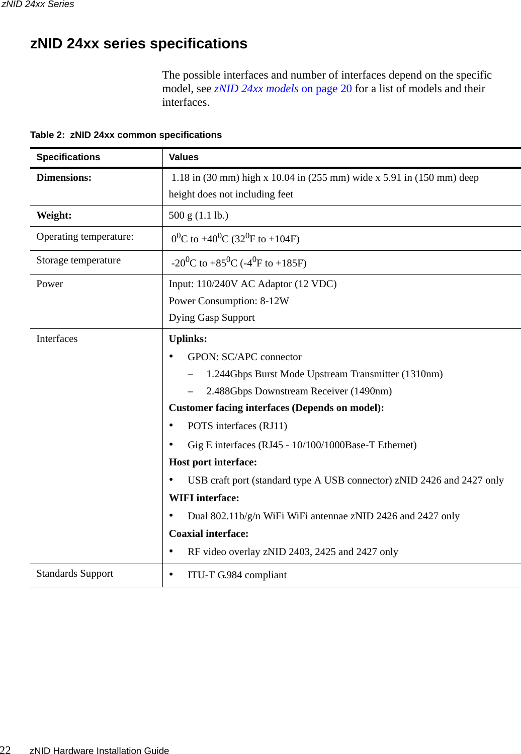
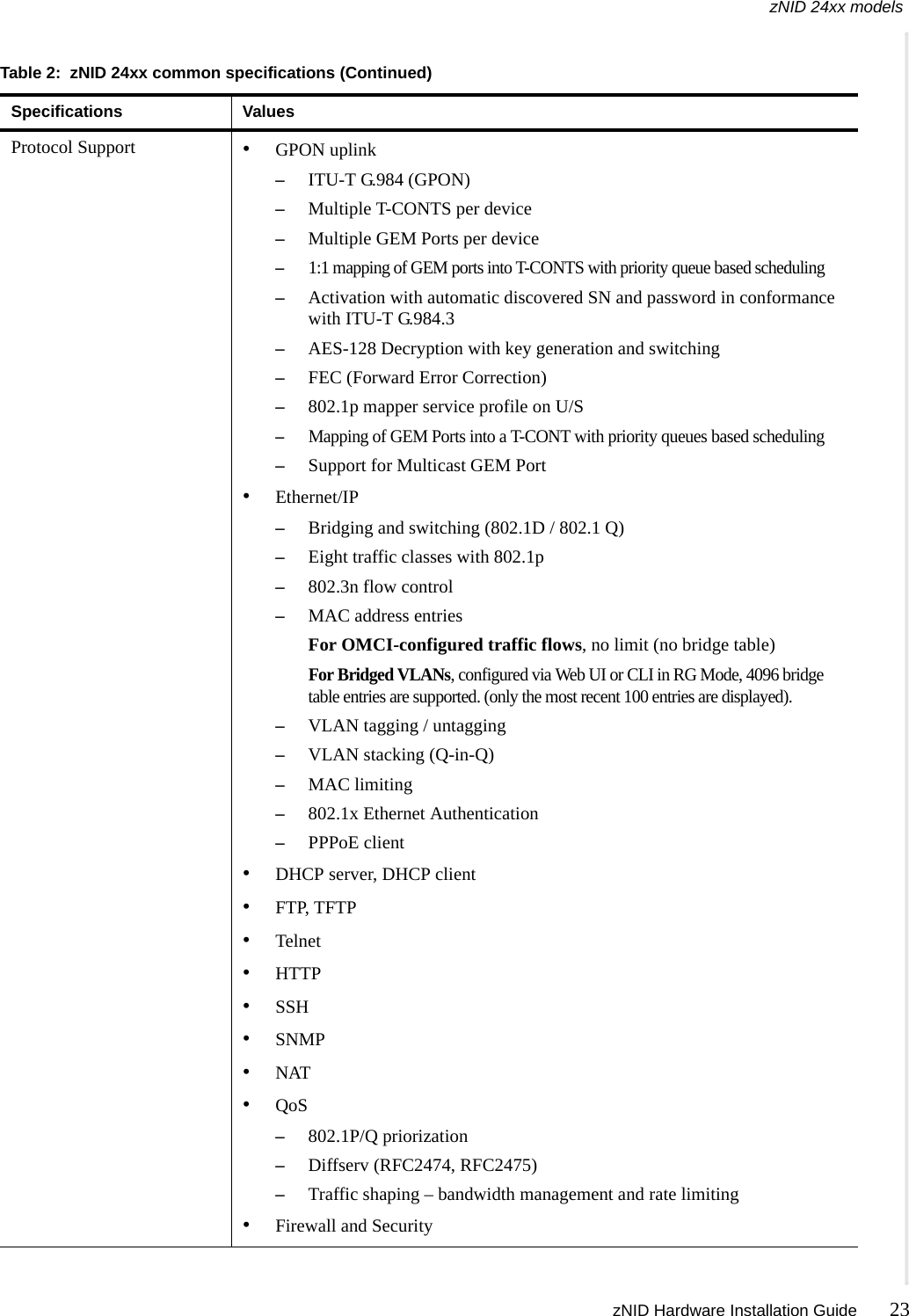
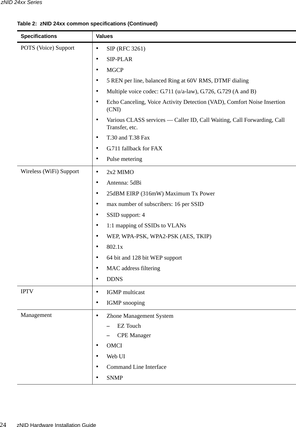
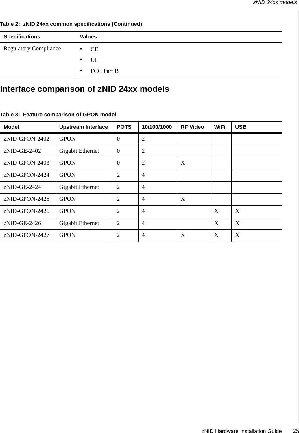
DASAN Zhone Solutions 242X GPON ONT User Manual zNID 24xx Hardware Installation Guide

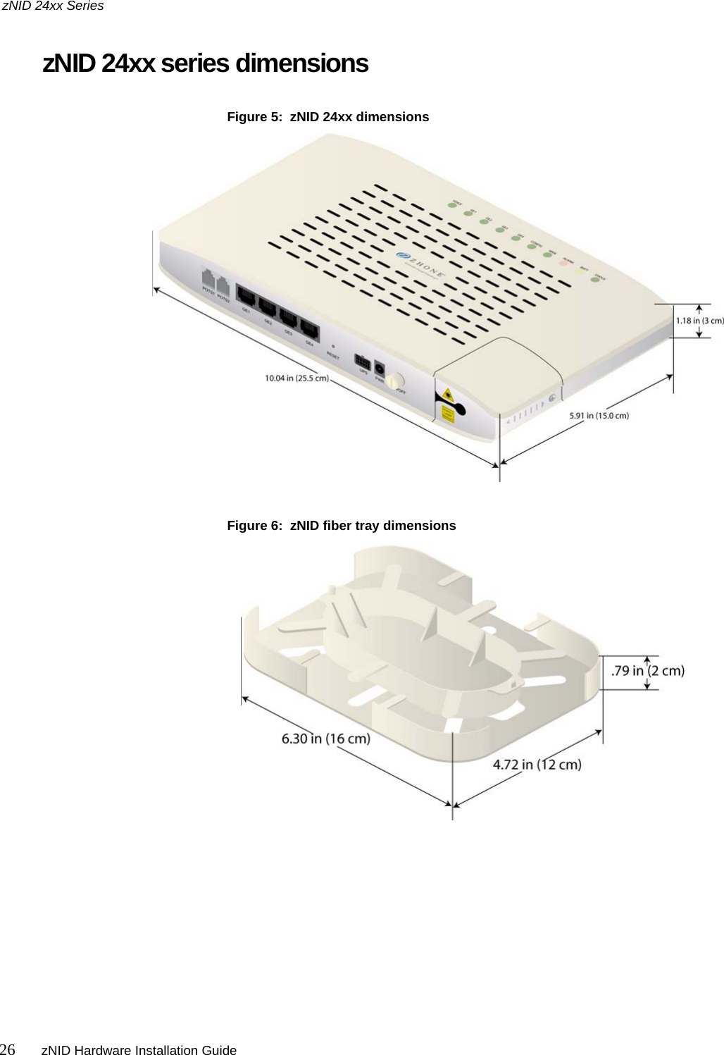
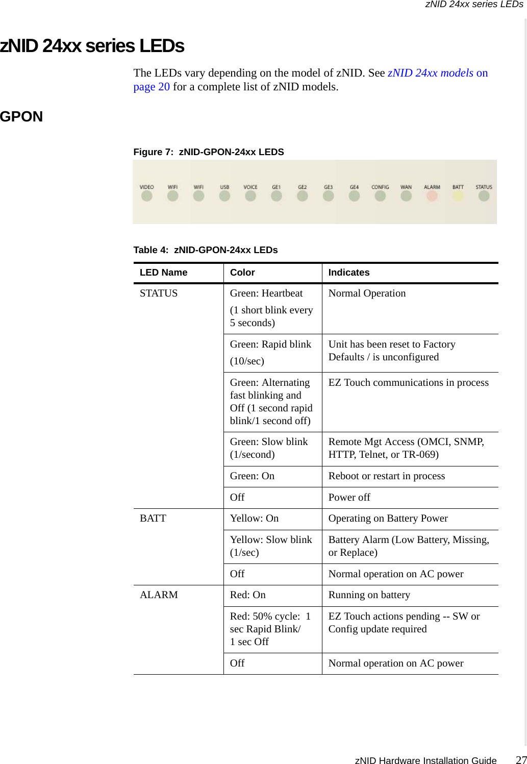
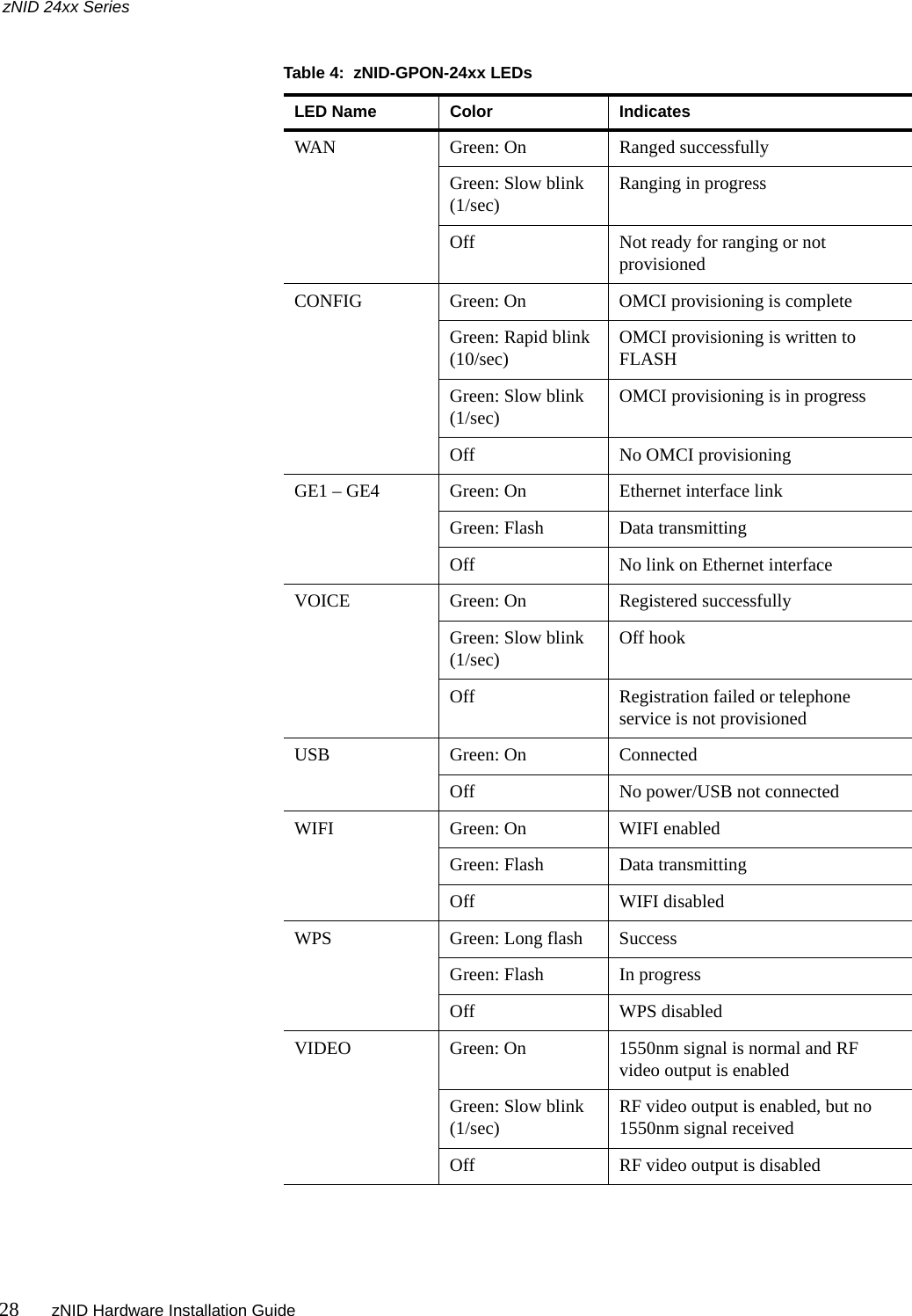
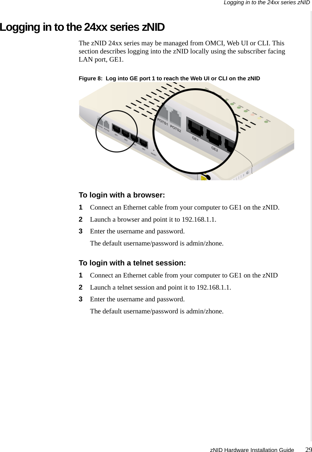
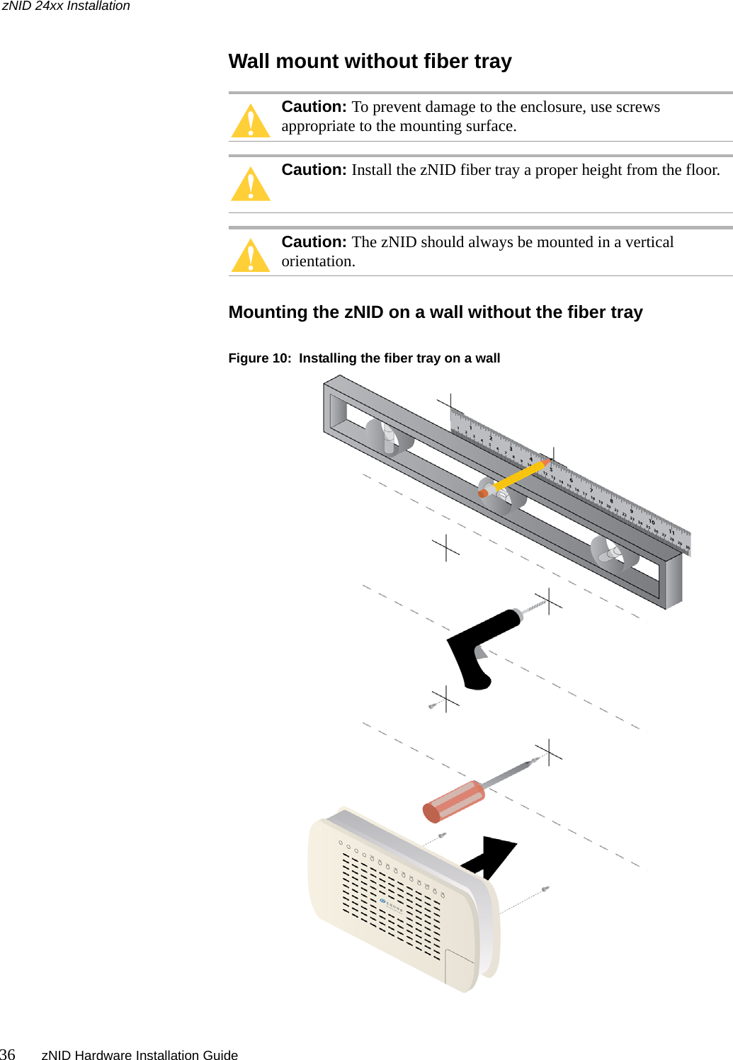
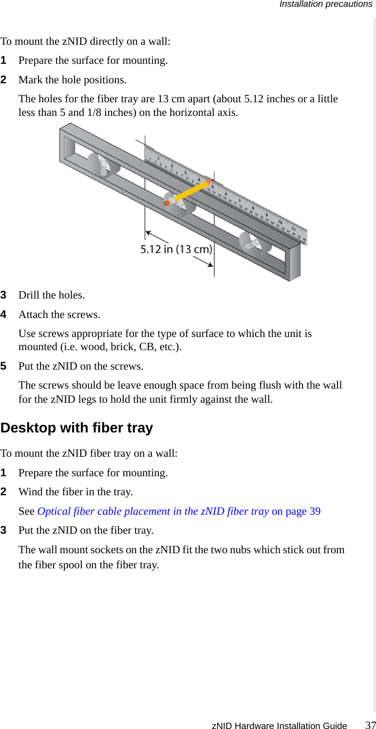
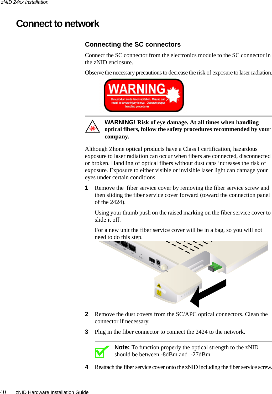
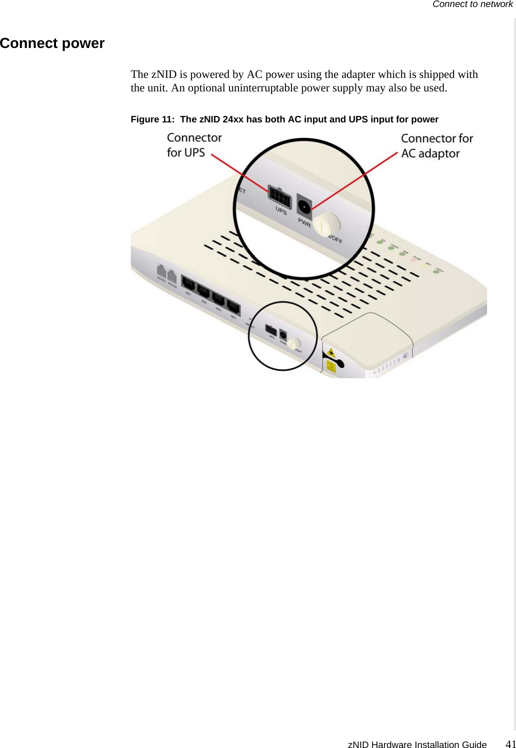
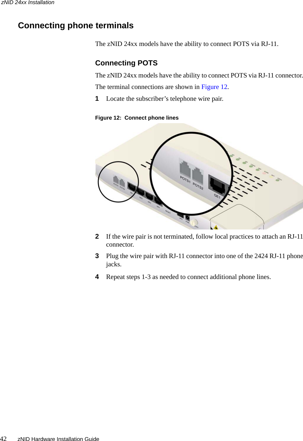
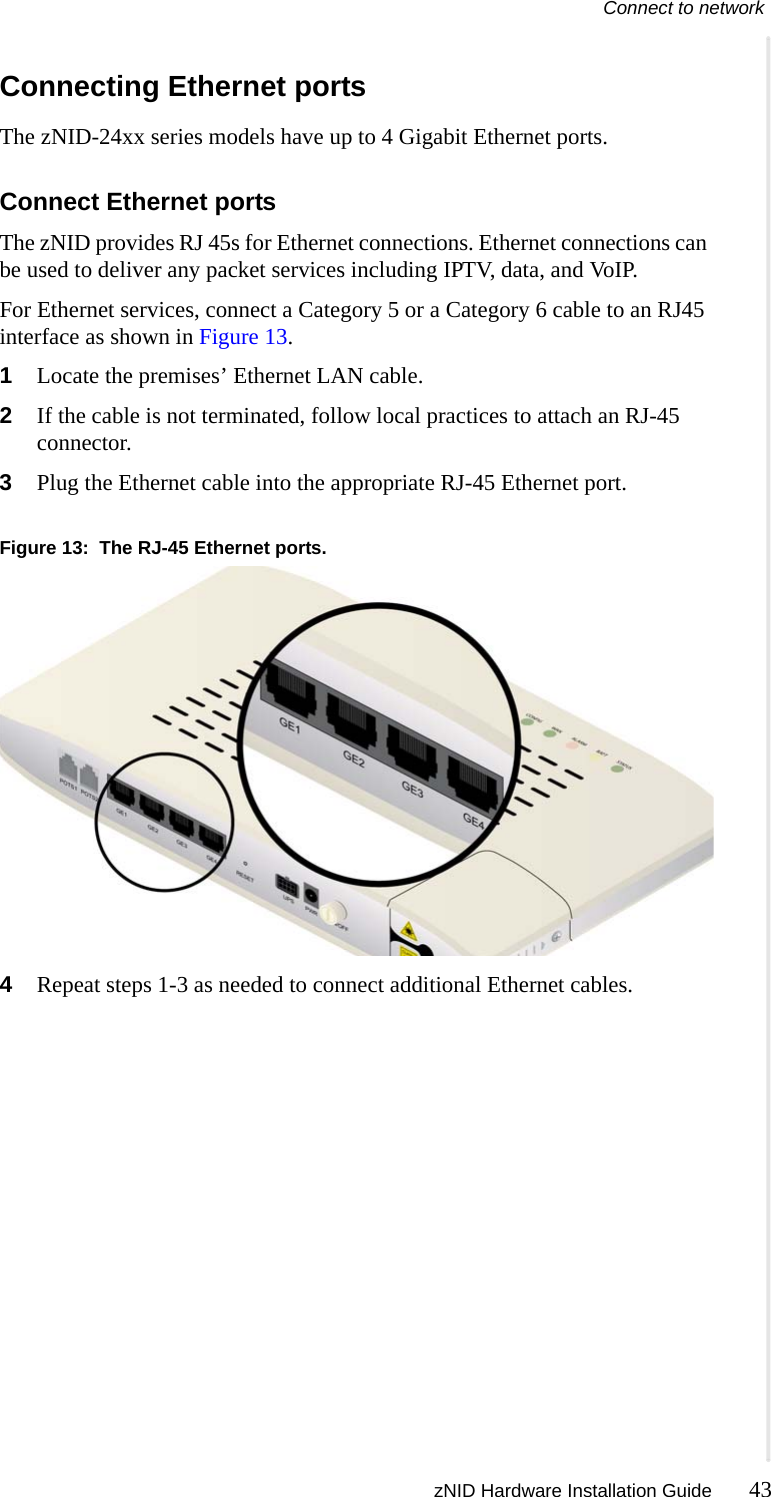
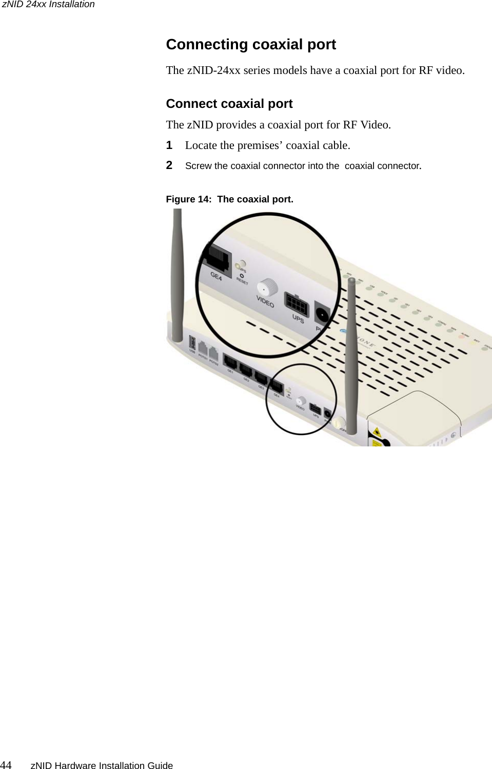
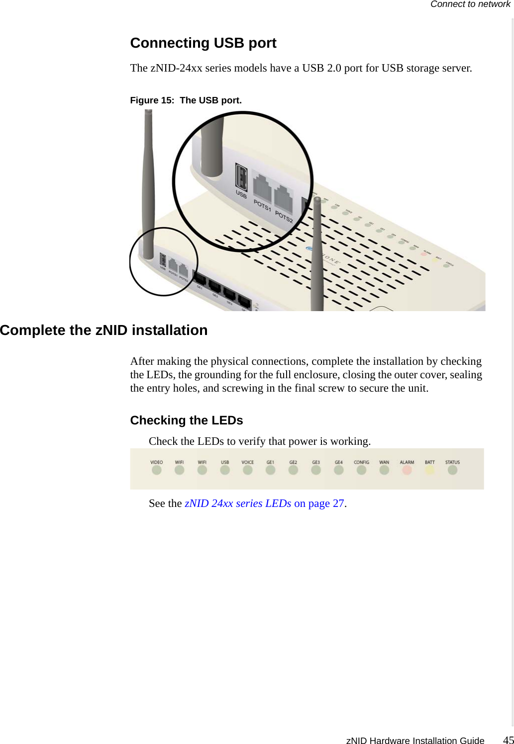
Zhone Technologies, Inc. GPON ONT zNID 24xx Hardware Installation Guide

Manual

   Zhone zNID 24xx SeriesHardware Installation GuideFor software version 2.4August 2011Document Part Number: 830-03747-01
2zNID Hardware Installation Guide   Zhone Technologies@Zhone Way7195 Oakport StreetOakland, CA 94621USA510.777.7000www.zhone.cominfo@zhone.comCOPYRIGHT C2000-2011 Zhone Technologies, Inc. and its licensors. All rights reserved.This publication is protected by copyright law. No part of this publication may be copied or distributed, transmitted, transcribed, stored in a retrieval system, or translated into any human or computer language in any form or by any means, electronic, mechanical, magnetic, manual or otherwise, or disclosed to third parties without the express written permission from Zhone Technologies, Inc.Bitstorm, EtherXtend, EZ Touch, IMACS, MALC, MXK, Raptor, SLMS, Z-Edge, Zhone, ZMS, zNID and the Zhone logo are trademarks of Zhone Technologies, Inc.Zhone Technologies makes no representation or warranties with respect to the contents hereof and specifically disclaims any implied warranties of merchantability, non infringement, or fitness for a particular purpose.Further, Zhone Technologies reserves the right to revise this publication and to make changes from time to time in the contents hereof without obligation of Zhone Technologies to notify any person of such revision or changes.
zNID Hardware Installation Guide 3TABLE OF CONTENTSStyle and notation conventions..............................................................................5Typographical conventions.......................................................................................6Related documentation.............................................................................................6Acronyms......................................................................................................................7Contacting Global Service and Support...............................................................9FCC Statement ..........................................................................................................10CE..................................................................................................................................10Important Safety Instructions................................................................................12Laser Safety Instructions.........................................................................................12General Instructions................................................................................................13Chapter 1 zNID 24xx Series....................................................................................................15Overview  ....................................................................................................................15zNID 24xx series components ................................................................................17zNID 24xx series features.......................................................................................19zNID 24xx models..................................................................................................20GPON models...................................................................................................21Gigabit Ethernet models...................................................................................21zNID 24xx series specifications..............................................................................22Interface comparison of zNID 24xx models...........................................................25zNID 24xx series dimensions................................................................................26zNID 24xx series LEDs............................................................................................27GPON......................................................................................................................27Logging in to the 24xx series zNID......................................................................29
Table of Contents4zNID Hardware Installation GuideChapter 2 zNID 24xx Installation..........................................................................................31Install the zNID ..........................................................................................................31Installation precautions...........................................................................................33Mount the zNID......................................................................................................33Wall mount with fiber tray...............................................................................34Wall mount without fiber tray..........................................................................36Desktop with fiber tray.....................................................................................37Manage the optical cable  .......................................................................................38Fiber handling...................................................................................................38Testing optical power.......................................................................................38Optical fiber cable placement in the zNID fiber tray..............................................39Connect to network.................................................................................................40Connect power ........................................................................................................41Connecting phone terminals ...................................................................................42Connecting Ethernet ports.......................................................................................43Connecting coaxial port..........................................................................................44Connecting USB port..............................................................................................45Complete the zNID installation ..............................................................................45Index......................................................................................................................................................47
zNID Hardware Installation Guide 5ABOUT THIS GUIDEThis guide is intended for use by installation technicians, system administrators, or network administrators. It explains how to install the zNID 24xx series enclosure, electronics and cabling. Style and notation conventionsThis document uses the following conventions to alert users to information that is instructional, warns of potential damage to system equipment or data, and warns of potential injury or death. Carefully read and follow the instructions included in this document.Caution: A caution alerts users to conditions or actions that could damage equipment or data.Note:  A note provides important supplemental or amplified information.Tip: A tip provides additional information that enables users to more readily complete their tasks.WARNING! A warning alerts users to conditions or actions that could lead to injury or death.WARNING! A warning alerts users to conditions or actions that could lead to injury caused by a laser.WARNING! This icon warns the user that metal surfaces can become hot to touch. Avoid contact or use caution when touching these surfaces.
About This Guide6zNID Hardware Installation GuideTypographical conventionsThe following typographical styles are used in this guide to represent specific types of information. Related documentationRefer to the following publication for additional information:•zNID Quick Installation Instructions for the zNID you are installing. These instructions are shipped with the zNID, but are also available on the Zhone website.•zNID 24xx Configuration Guide — explains how to use the zNID web interface and describes the system commands and parameters. Refer to the release notes for software installation information and for changes in features and functionality of the product (if any).Bold Used for names of buttons, dialog boxes, icons, menus, profiles when placed in body text, and property pages (or sheets). Also used for commands, options, parameters in body text, and user input in body text.Fixed Used in code examples for computer output, file names, path names, and the contents of online files or directories.Fixed Bold Used in code examples for text typed by users.Fixed Bold ItalicUsed in code examples for variable text typed by users.Italic Used for book titles, chapter titles, file path names, notes in body text requiring special attention, section titles, emphasized terms, and variables.PLAIN UPPER CASE Used for environment variables.
Acronyms zNID Hardware Installation Guide 7AcronymsThe following acronyms are related to Zhone products and may appear throughout this manual:Table 1:  Acronyms and their descriptionsAcronym DescriptionActive E Active Ethernet, also known as Gigabit EthernetAPC Angled physical contact (for fiber connector)Coax Coaxial cableCNI Comfort Noise InsertionCPE Consumer Premises EquipmentDHCP server Dynamic host configuration protocol serverEZ touch™ Zhone’s implementation for managing CPEs and zNIDsGigE Gigabit EthernetGPON Gigabit passive optical networkHPNA  Home phone line networking allianceIPTV Internet protocol TVLED Light-emitting diodeMALC Multi-access line concentratorMDU Multiple Dwelling UnitMIB Management information basesMoCA Multimedia over Coax AllianceOLT Optical Line TerminatorONT Optical Network TerminatorONU Optical Network UnitPoE Power over EthernetPPPoE Point-to-point protocol over EthernetQoS Quality of serviceRF Radio FrequencyRFoG Radio Frequency over GlassSC adaptor Subscriber connector adaptorSIP Session initiation protocolSNMP Simple network management protocol
About This Guide8zNID Hardware Installation GuideT1/E1 T1 is Trunk line 1 (or DS 1, digital signal level 1). E1 is the European equivalent, though there are a number of differences between the North American T1 and the European E1.UPC Ultra physical contact (for fiber connector)Wi-Fi Wireless local area network (trademark of Wi-Fi alliance)VAD Voice Activity DetectionVOIP Voice over IPzNID Zhone Network Interface DeviceZMS Zhone Management SystemTable 1:  Acronyms and their descriptions (Continued)Acronym Description
Contacting Global Service and Support zNID Hardware Installation Guide 9Contacting Global Service and SupportSupport for this product is provided by your Internet service provider
About This Guide10 zNID Hardware Installation GuideFCC StatementThis equipment has been tested and found to comply with the limits for a Class B digital device, pursuant to Part 15 of the FCC Rules.  These limits are designed to provide reasonable protection against harmful interference in a residential installation.  This equipment generates, uses and can radiate radio frequency energy and, if not installed and used in accordance with the instructions, may cause harmful interference to radio communications.  However, there is no guarantee that interference will not occur in a particular installation.  If this equipment does cause harmful interference to radio or television reception, which can be determined by turning the equipment off and on, the user is encouraged to try to correct the interference by one of the following measures:•Reorient or relocate the receiving antenna. •Increase the separation between the equipment and receiver.•Connect the equipment into an outlet on a circuit different from that to which the receiver is connected. •Consult the dealer or an experienced radio/TV technician for help. FCC Caution: Any changes or modifications not expressly approved by the party responsible for compliance could void the user's authority to operate this equipment. This device complies with Part 15 of the FCC Rules. Operation is subject to the following two conditions: (1) This device may not cause harmful interference, and (2) this device must accept any interference received, including interference that may cause undesired operation. CEFor the following equipment: •ZNID-GPON-2402-XXX•ZNID-GPON-2403-XXX•ZNID-GPON-2424-XXX•ZNID-GPON-2425-XXX•ZNID-GPON-2426-XXX•ZNID-GPON-2427-XXXThe xxx suffix, 2-3 alphanumeric characters identify the sales region or specific customer with customized LOGO or software.Is herewith confirmed to comply with the requirements setout in the Council Directive on the Approximation of the Laws of the Member States relating to Electromagnetic Compatibility (2004/108/EC), Low-voltageDirective (2006/
CE zNID Hardware Installation Guide 1195/EC) and R&TTE (1999/5/EC).The equipment has passed The test was performed according to thefollowing European standards:•ETSI EN 301 489-17 V2.1.1: 2009•ETSI EN 301 489-1 V1.8.1: 2008•ETSI EN 300 328 V1.7.1: 2006•EN 62311: 2008•EN 60950-1: 2006+A11 2009
About This Guide12 zNID Hardware Installation GuideImportant Safety InstructionsRead and follow all warning notices and instructions marked on the product and included in the manual.Laser Safety InstructionsZhone equipment and associated optical test sets use laser sources that emit light energy into fiber cables. This energy is within the red (visible) and infrared (invisible) regions of the electromagnetic spectrum.Laser products are subject to federal and state or provincial regulations, and local practices.  Regulation 21 CFR 1040 of the U.S. Bureau of Radiological Health requires manufacturers to certify each laser product as Class I, II, III, or IV, depending upon the characteristics of the laser radiation emitted. In terms of health and safety, Class I products present the least hazard (none at all), while Class IV products present the greatest hazard.Although Zhone optical products have a Class I certification, hazardous exposure to laser radiation can occur when fibers connecting system components are disconnected or broken.Certain procedures carried out during testing require the handling of optical fibers without dust caps and therefore increase the risk of exposure. Exposure to either visible or invisible laser light can damage your eyes under certain conditions.Read and observe the following precautions to decrease the risk of exposure to laser radiation.WARNING! Risk of eye damage. At all times, when handling optical fibers, follow the safety procedures recommended by your company.WARNING! Avoid direct exposure to fiber ends or optical connector ends. Laser radiation may be present and can damage your eyes.WARNING! Never look into an active optical fiber or an optical fiber connector opening of an active or powered-up unit.Note: When working with optical fibers, take these precautions:•Wear safety glasses when installing optical fibers.•Clean hands after handling optical fibers. Small pieces of glass are not always visible and can cause eye damage. Get medical assistance immediately for any glass that comes into eye contact.
Important Safety Instructions zNID Hardware Installation Guide 13•Prevent direct exposure to optical fiber ends or optical connector ends where laser signals are directly accessed. Do not handle pieces of optical fiber with fingers. Use tweezers or adhesive tape to lift and discard any loose optical fiber ends.•Wear rubber gloves to clean optical connectors. The gloves prevent direct contact with the isopropyl alcohol and prevent contamination of the ferrules with skin oils.•Place all optical fiber clippings in a plastic container provided for that purpose.•Handle optical fibers with caution. Place the optical fibers in a safe location during installation.•Follow the manufacturer instructions when using an optical test set. Incorrect calibration or control settings can create hazardous levels of radiation.General InstructionsOther precautions to take before installing or servicing the product are as follows:•Never install telephone wiring during a lightning storm.•Never touch uninsulated telephone wires or terminals unless the telephone line has first been disconnected at the network interface.•Use caution when installing or modifying telephone lines.•Only authorized service technicians can service this product.Unauthorized service to this product can cause exposure to dangerous high-voltage points or other risks and may result in injury or damage to the unit and void all warranties.•Special cables, which may be required by the regulatory inspection authority for the installation site, are the responsibility of the buyer.•When installed in the final configuration, the product must comply with the applicable Safety Standards and regulatory requirements of the country in which it is installed. If necessary, consult with the appropriate regulatory agencies and inspection authorities to ensure compliance.•Install the zNID in accordance with national and local electric codes in order to meet all applicable requirements. Consult a qualified electrical consultant.
About This Guide14 zNID Hardware Installation Guide
zNID Hardware Installation Guide 15   ZNID 24XX SERIESThis chapter describes the 24xx series of zNIDs. It includes the following sections:•Overview, page 15•zNID 24xx series features, page 19•zNID 24xx models, page 20•zNID 24xx series specifications, page 22•zNID 24xx series dimensions, page 26•zNID 24xx series LEDs, page 27•Logging in to the 24xx series zNID, page 29Overview The zNID 24xx Series (Zhone Network Interface Device) is a family of indoor residential GPON ONTs which are standards based Consumer Premises Equipment (CPE) designed for advanced triple-play deployments. The indoor models in Zhone's zNID product line of ONT's provide a lower cost alternative to outdoor ONT solutions. The small package contains many features including QoS, VoIP, and multicast video support. The zNID ONT is only one component in the PON network. Zhone provides the entire FTTx solution to our customers including the OLT, splitters, cabinets, and the ONT.The 24xx indoor ONT is designed for high performance applications. Depending on model hardware features include 10/100/1000Mbps LAN Ports and POTS Voice FXS ports, RF video, WiFi and USB in a compact enclosure for indoor use. zNID 24xx Series units may be installed as a desktop or, wall mounted and is powered via an AC Adaptor.The zNID 24xx Series are ideal for triple-play service deployments in Fiber-to-the-Home/Premise application. Industry standard SIP and MGCP voice signaling provides reliable voice services while Zhone's experience with packet voice ensures interoperability and support with a large number of soft switches. All 24xx series Single Family Unit (SFU) ONTs provide the same voice features found on the 42xx series of outdoor residential ONTs and 9xxx series of outdoor Multiple Dwelling Unit (MDU) ONTs. SIP-PLAR signaling is
zNID 24xx Series16 zNID Hardware Installation Guide   supported for connection via Zhone's Voice Gateway to traditional Class 5 TDM switches, while both MGCP and SIP are supported for direct connection to a VoIP Softswitch. This flexibility allows Zhone's 42xx, 9xxx and 24xx Series ONTs to work in nearly all Telco networks, with interoperability support for a broad array of Softswitches.The Ethernet ports can be separated into different services allowing the configuration of dedicated ports for IP video and data.Compliant with standard OMCI definition, 2424 is manageable at remote side and supports the full range FCAPS functions including supervision, monitoring and maintenance.Zhone provides THE complete PON solution: ONT, OLT, splitter, EDFA, RF Transmitters, and cabinet solutions are available from Zhone because our customers want to buy a complete and fully tested solution from one trusted source.The zNID 24xx series may be managed by •EZ Touch (Zhone’s CPE and zNID management application)•Zhone Management System (ZMS)•Web (HTTP)•Command Line Interface (CLI/Telnet/SSH)More information about managment capabilities see the zNID Administrator and Operators Guide.
Overview zNID Hardware Installation Guide 17   zNID 24xx series componentsThe zNID 24xx series indoor ONTs provide a variety of interfaces for triple play deployments. These indoor units may be mounted to a wall or placed on a desktop.Figure 1:  The interfaces, displays and buttons for the zNID 24xxDepending upon the zNID model selected, the interfaces on the zNID can include:•Two or four Gigabit Ethernet RJ45 ports•Two phone ports (POTS)•WiFi antennae•RF video•USB•Connection for uninterruptable power supply (UPS)
zNID 24xx Series18 zNID Hardware Installation Guide   Figure 2:  The zNID 24xx series attaches to a fiber tray baseFigure 3:  The unit may also be wall mounted, with or without a fiber tray
zNID 24xx series features zNID Hardware Installation Guide 19   zNID 24xx series featuresUnder ideal circumstances, GPON can reach up to 20 or 30 km, however the practical limit is 12 km (about eight miles). Reach is dependent on the configuration of the optical distribution network (ODN).All 24xx series ONTs are designed for indoor use.The 24xx series of zNIDs share a common SW architecture with the 42xx and 9xxx series of zNIDs, including the same intuitive Web interface and command line interface. The zNID is also managed by the Zhone Network Management System (ZMS),using SNMP. Software upgrades and configuration backups can be handled automatically by the ZMS using the EZ Touch management feature.This section covers:•zNID 24xx models•zNID 24xx series specifications•zNID 24xx series dimensionsThe zNID enables service providers to provide voice, data, and video services along with advanced IP and data support.
zNID 24xx Series20 zNID Hardware Installation Guide   zNID 24xx modelsFigure 4:  zNID 24xx modelsCaution: To ensure adequate ventilation, nothing should be placed on the top of the zNID 24xx. zNID 24xx units should not be stacked.
zNID 24xx models zNID Hardware Installation Guide 21   GPON modelsThe zNID series GPON models have the following interfaces:Gigabit Ethernet modelsThe zNID series Gigabit Ethernet models have the following interfaces:Model DescriptionzNID-GPON-2402 GPON Uplink, 2 GigEzNID-GPON-2403 GPON Uplink, 2 GigE, RFVzNID-GPON-2424 GPON Uplink, 2 POTS, 4 GigEzNID-GPON-2425 GPON Uplink, 2 POTS, 4 GigE, RFVzNID-GPON-2426 GPON Uplink, 2 POTS, 4 GigE, WiFi, USBzNID-GPON-2427 GPON Uplink, 2 POTS, 4 GigE, WiFi, RFV, USBModel DescriptionzNID-GE-2402 GE Uplink, 2 GigEzNID-GE-2424 GE Uplink, 2 POTS, 4 GigEzNID-GE-2426 GE Uplink, 2 POTS, 4 GigE, WiFi, USB
zNID 24xx Series22 zNID Hardware Installation Guide   zNID 24xx series specificationsThe possible interfaces and number of interfaces depend on the specific model, see zNID 24xx models on page 20 for a list of models and their interfaces.Table 2:  zNID 24xx common specificationsSpecifications ValuesDimensions:  1.18 in (30 mm) high x 10.04 in (255 mm) wide x 5.91 in (150 mm) deepheight does not including feetWeight: 500 g (1.1 lb.)Operating temperature:  00Cto+400C (320F to +104F)Storage temperature  -200Cto+850C (-40F to +185F)Power Input: 110/240V AC Adaptor (12 VDC)Power Consumption: 8-12WDying Gasp SupportInterfaces Uplinks:•GPON: SC/APC connector –1.244Gbps Burst Mode Upstream Transmitter (1310nm)–2.488Gbps Downstream Receiver (1490nm)Customer facing interfaces (Depends on model):•POTS interfaces (RJ11)•Gig E interfaces (RJ45 - 10/100/1000Base-T Ethernet)Host port interface:•USB craft port (standard type A USB connector) zNID 2426 and 2427 onlyWIFI interface:•Dual 802.11b/g/n WiFi WiFi antennae zNID 2426 and 2427 onlyCoaxial interface:•RF video overlay zNID 2403, 2425 and 2427 onlyStandards Support •ITU-T G.984 compliant
zNID 24xx models zNID Hardware Installation Guide 23   Protocol Support •GPON uplink–ITU-T G.984 (GPON)–Multiple T-CONTS per device–Multiple GEM Ports per device–1:1 mapping of GEM ports into T-CONTS with priority queue based scheduling–Activation with automatic discovered SN and password in conformance with ITU-T G.984.3–AES-128 Decryption with key generation and switching–FEC (Forward Error Correction)–802.1p mapper service profile on U/S–Mapping of GEM Ports into a T-CONT with priority queues based scheduling–Support for Multicast GEM Port•Ethernet/IP–Bridging and switching (802.1D / 802.1 Q)–Eight traffic classes with 802.1p–802.3n flow control–MAC address entriesFor OMCI-configured traffic flows, no limit (no bridge table)For Bridged VLANs, configured via Web UI or CLI in RG Mode, 4096 bridge table entries are supported. (only the most recent 100 entries are displayed).–VLAN tagging / untagging–VLAN stacking (Q-in-Q)–MAC limiting–802.1x Ethernet Authentication–PPPoE client•DHCP server, DHCP client•FTP, TFTP•Telnet•HTTP•SSH•SNMP•NAT•QoS–802.1P/Q priorization–Diffserv (RFC2474, RFC2475)–Traffic shaping – bandwidth management and rate limiting•Firewall and SecurityTable 2:  zNID 24xx common specifications (Continued)Specifications Values
zNID 24xx Series24 zNID Hardware Installation Guide   POTS (Voice) Support •SIP (RFC 3261)•SIP-PLAR•MGCP•5 REN per line, balanced Ring at 60V RMS, DTMF dialing•Multiple voice codec: G.711 (u/a-law), G.726, G.729 (A and B)•Echo Canceling, Voice Activity Detection (VAD), Comfort Noise Insertion (CNI)•Various CLASS services — Caller ID, Call Waiting, Call Forwarding, Call Transfer, etc.•T.30 and T.38 Fax•G.711 fallback for FAX•Pulse meteringWireless (WiFi) Support •2x2 MIMO•Antenna: 5dBi•25dBM EIRP (316mW) Maximum Tx Power•max number of subscribers: 16 per SSID•SSID support: 4•1:1 mapping of SSIDs to VLANs•WEP, WPA-PSK, WPA2-PSK (AES, TKIP)•802.1x•64 bit and 128 bit WEP support•MAC address filtering•DDNSIPTV •IGMP multicast•IGMP snoopingManagement •Zhone Management System–EZ Touch–CPE Manager•OMCI•Web UI•Command Line Interface•SNMPTable 2:  zNID 24xx common specifications (Continued)Specifications Values
zNID 24xx models zNID Hardware Installation Guide 25   Interface comparison of zNID 24xx modelsRegulatory Compliance  •CE•UL•FCC Part BTable 2:  zNID 24xx common specifications (Continued)Specifications ValuesTable 3:  Feature comparison of GPON modelModel Upstream Interface POTS 10/100/1000 RF Video WiFi USBzNID-GPON-2402 GPON 0 2zNID-GE-2402 Gigabit Ethernet 0 2zNID-GPON-2403 GPON 0 2 XzNID-GPON-2424 GPON 2 4zNID-GE-2424 Gigabit Ethernet 2 4zNID-GPON-2425 GPON 2 4 XzNID-GPON-2426 GPON 2 4 X XzNID-GE-2426 Gigabit Ethernet 2 4 X XzNID-GPON-2427 GPON 2 4 X X X
zNID 24xx Series26 zNID Hardware Installation Guide   zNID 24xx series dimensionsFigure 5:  zNID 24xx dimensionsFigure 6:  zNID fiber tray dimensions
zNID 24xx series LEDs zNID Hardware Installation Guide 27   zNID 24xx series LEDsThe LEDs vary depending on the model of zNID. See zNID 24xx models on page 20 for a complete list of zNID models.GPONFigure 7:  zNID-GPON-24xx LEDSTable 4:  zNID-GPON-24xx LEDsLED Name Color IndicatesSTATUS Green: Heartbeat (1 short blink every 5 seconds)Normal OperationGreen: Rapid blink(10/sec)Unit has been reset to Factory Defaults / is unconfiguredGreen: Alternating fast blinking and Off (1 second rapid blink/1 second off)EZ Touch communications in processGreen: Slow blink (1/second) Remote Mgt Access (OMCI, SNMP, HTTP, Telnet, or TR-069)Green: On Reboot or restart in processOff Power offBATT Yellow: On Operating on Battery PowerYellow: Slow blink (1/sec) Battery Alarm (Low Battery, Missing, or Replace)Off Normal operation on AC powerALARM Red: On Running on batteryRed: 50% cycle:  1 sec Rapid Blink/1 sec OffEZ Touch actions pending -- SW or Config update requiredOff Normal operation on AC power
zNID 24xx Series28 zNID Hardware Installation Guide   WAN Green: On Ranged successfullyGreen: Slow blink (1/sec) Ranging in progressOff Not ready for ranging or not provisioned CONFIG Green: On OMCI provisioning is completeGreen: Rapid blink (10/sec) OMCI provisioning is written to FLASHGreen: Slow blink (1/sec) OMCI provisioning is in progressOff No OMCI provisioningGE1 – GE4 Green: On Ethernet interface linkGreen: Flash Data transmittingOff No link on Ethernet interfaceVOICE Green: On Registered successfullyGreen: Slow blink (1/sec) Off hookOff Registration failed or telephone service is not provisionedUSB Green: On ConnectedOff No power/USB not connectedWIFI Green: On WIFI enabledGreen: Flash Data transmittingOff WIFI disabledWPS Green: Long flash SuccessGreen: Flash In progressOff WPS disabledVIDEO Green: On 1550nm signal is normal and RF video output is enabledGreen: Slow blink (1/sec) RF video output is enabled, but no 1550nm signal receivedOff RF video output is disabledTable 4:  zNID-GPON-24xx LEDsLED Name Color Indicates
Logging in to the 24xx series zNID zNID Hardware Installation Guide 29   Logging in to the 24xx series zNIDThe zNID 24xx series may be managed from OMCI, Web UI or CLI. This section describes logging into the zNID locally using the subscriber facing LAN port, GE1.Figure 8:  Log into GE port 1 to reach the Web UI or CLI on the zNIDTo login with a browser:1Connect an Ethernet cable from your computer to GE1 on the zNID.2Launch a browser and point it to 192.168.1.1.3Enter the username and password.The default username/password is admin/zhone.To login with a telnet session:1Connect an Ethernet cable from your computer to GE1 on the zNID2Launch a telnet session and point it to 192.168.1.1.3Enter the username and password.The default username/password is admin/zhone.
zNID 24xx Series30 zNID Hardware Installation Guide
zNID Hardware Installation Guide 31  ZNID 24XX INSTALLATIONThis chapter can be used as separate installation instructions. This chapter explains how to unpack the zNID 24xx and install the zNID 24xx hardware. It includes the following sections:•Install the zNID, page 31•Overview of zNID 24xx series installation, page 32Install the zNIDThis section describes the procedures for installing the zNID. The overiew procedure provides options for wall mounting or placing the zNID on a surface with or without the optional fiber tray.This section contains the following topics:•Overview of zNID 24xx series installation on page 32•Installation precautions on page 33•Mount the zNID on page 33–Wall mount with fiber tray on page 34–Wall mount without fiber tray on page 36–Desktop with fiber tray on page 37•Manage the optical cable on page 38•Fiber handling on page 38•Testing optical power on page 38•Optical fiber cable placement in the zNID fiber tray on page 39•Connect to network on page 40•Connect power on page 41•Connecting phone terminals on page 42•Connecting Ethernet ports on page 43•Complete the zNID installation on page 45
zNID 24xx Installation32 zNID Hardware Installation Guide  Overview of zNID 24xx series installation1Select the locationEnsure that the environment is free of dust and excessive moisture and has sufficient ventilation.The zNID may be installed in a vertical or horizontal orientation (wall or desktop. The zNID should be placed in a clean dry place as is appropriate for electronic equipmentInstallation precautions on page 33Install the system in reasonable proximity to all equipment or rooms where the TV or computer reside for straightforward connections.2Mount the zNID.Mount the zNID on page 333Install service fiber to the zNID.Connect to network on page 404Connect AC power and/or UPSConnect power on page 415Connect the subscriber facing servicesaConnect telephone (POTS) serviceSee Connecting POTS on page 42.bConnect Ethernet serviceSee Connect Ethernet ports on page 43.cConnect Ethernet serviceSee Connect coaxial port on page 44.6CompleteChecking the LEDs on page 45
Installation precautions zNID Hardware Installation Guide 33  Installation precautionsMaximum operating temperature should not exceed the range of 0° C to 40° C (32° F to 104° F).Ensure that proper cable grades are used for all system and network connections. For best results, use the cables and connectors recommended in this document.Connect the system to the power supply circuit as described in this document.Before making fiber connections, be sure that the optical cable fiber tips and components are clean and free of dust and debris. Follow established cleaning procedures if required.Note: Sharp bends in fiber cables create undesirable optical attenuation or loss. The zNID fiber tray provides fiber spools and hooks to avoid sharp bends in the fiber cable. A minimum bend radius of 30 mm (1.2 in) is recommended for stripped fiber.Mount the zNIDThe zNID enclosure can be mounted on a vertical surface or a horizontal surface (wall or desktop).•Wall mount with fiber tray on page 34•Wall mount without fiber tray on page 36•Desktop with fiber tray on page 37
zNID 24xx Installation34 zNID Hardware Installation Guide  Wall mount with fiber trayThe zNID fiber tray can be mounted on a wall using four screws. Caution: To prevent damage to the enclosure, use screws appropriate to the mounting surface.Caution: Install the zNID fiber tray a proper height from the floor.Mounting the zNID fiber tray on a wallTo mount the zNID fiber tray on a wall:Figure 9:  Installing the fiber tray on a wall
Installation precautions zNID Hardware Installation Guide 35  1Prepare the surface for mounting.2Hold the bracket level in the desired location and mark the hole positions.The holes for the fiber tray are 8 cm apart (about 3.15 inches or a little less than 3 and 3/16 inches) on the horizontal axis and 4 cm apart (about 1.57 inches or about 1 and 9/16 inches) on the vertical axis.3Drill the holes.4Line up the fiber tray with the screw holes and attach the screws.Use attaching hardware appropriate for the type of surface to which the unit is mounted (i.e. wood, brick, CB, etc.). Use shims when necessary to keep the zNID vertical.5Wind the fiber in the tray.See Optical fiber cable placement in the zNID fiber tray on page 396Put the zNID on the fiber tray.The wall mount sockets on the zNID fit the two nubs which stick out from the fiber spool on the fiber tray.
zNID 24xx Installation36 zNID Hardware Installation Guide  Wall mount without fiber trayCaution: To prevent damage to the enclosure, use screws appropriate to the mounting surface.Caution: Install the zNID fiber tray a proper height from the floor.Caution: The zNID should always be mounted in a vertical orientation.Mounting the zNID on a wall without the fiber trayFigure 10:  Installing the fiber tray on a wall
Installation precautions zNID Hardware Installation Guide 37  To mount the zNID directly on a wall:1Prepare the surface for mounting.2Mark the hole positions.The holes for the fiber tray are 13 cm apart (about 5.12 inches or a little less than 5 and 1/8 inches) on the horizontal axis.3Drill the holes.4Attach the screws.Use screws appropriate for the type of surface to which the unit is mounted (i.e. wood, brick, CB, etc.).5Put the zNID on the screws.The screws should be leave enough space from being flush with the wall for the zNID legs to hold the unit firmly against the wall.Desktop with fiber trayTo mount the zNID fiber tray on a wall:1Prepare the surface for mounting.2Wind the fiber in the tray.See Optical fiber cable placement in the zNID fiber tray on page 393Put the zNID on the fiber tray.The wall mount sockets on the zNID fit the two nubs which stick out from the fiber spool on the fiber tray.
zNID 24xx Installation38 zNID Hardware Installation Guide  Manage the optical cable When making a fiber optic connection, avoid touching the fiber cable ends to the outside of the mating connector. Touching can contaminate the connectors.Fiber handlingBefore making any connections, be sure that the optical cable fiber tips and components are clean and free of dust and debris.The zNID fiber tray provides fiber spools and hooks to avoid sharp bends in the fiber cable. A minimum bend radius of 30 mm is recommended for stripped fiber and larger fiber needs a larger bend radius to guarantee the specified system performance. Note: Sharp bends in fiber cables create undesirable optical attenuation or loss.Testing optical powerTable 5 specifies how much laser power to expect on the fiber.Table 5:  Optical values for the triplexerParameter 1490 nm 1550 nmDamage Level +5 dBm +5 dBmOptical Overload -8 dBm +2 dBmMinimal Optical Signal -28.5 dBm -8 dBmMid Range Optical Value -17 dBm -4 dBm
Installation precautions zNID Hardware Installation Guide 39  Optical fiber cable placement in the zNID fiber trayUsing a fiber tray involves routing the optical fiber around the spools, then physically to the SC connector in the zNID.Note: Sharp bends in fiber cables create undesirable optical attenuation or loss. The zNID enclosure provides fiber spools and hooks to avoid sharp bends in the fiber cable. A minimum bend radius of 30 mm (1.2 in) is recommended for stripped fiber.To place the fiber cable in the fiber tray:1Inspect and clean the fiber connector to ensure it is free of impurities. 2Make sure the fiber segment is properly installed in the fiber tray, excess cable is wrapped around fiber reels without having improper bends leaving enough loose cable so that it will not take too sharp of a bend to connect to the zNID..3Test the fiber cable to verify clean signals.Note: It is recommended that the fiber cable be tested before finishing.
zNID 24xx Installation40 zNID Hardware Installation Guide  Connect to networkConnecting the SC connectorsConnect the SC connector from the electronics module to the SC connector in the zNID enclosure.Observe the necessary precautions to decrease the risk of exposure to laser radiation.WARNING! Risk of eye damage. At all times when handling optical fibers, follow the safety procedures recommended by your company.Although Zhone optical products have a Class I certification, hazardous exposure to laser radiation can occur when fibers are connected, disconnected or broken. Handling of optical fibers without dust caps increases the risk of exposure. Exposure to either visible or invisible laser light can damage your eyes under certain conditions.1Remove the  fiber service cover by removing the fiber service screw and then sliding the fiber service cover forward (toward the connection panel of the 2424). Using your thumb push on the raised marking on the fiber service cover to slide it off.For a new unit the fiber service cover will be in a bag, so you will not need to do this step. 2Remove the dust covers from the SC/APC optical connectors. Clean the connector if necessary.3Plug in the fiber connector to connect the 2424 to the network.Note: To function properly the optical strength to the zNID should be between -8dBm and  -27dBm4Reattach the fiber service cover onto the zNID including the fiber service screw.
Connect to network zNID Hardware Installation Guide 41  Connect powerThe zNID is powered by AC power using the adapter which is shipped with the unit. An optional uninterruptable power supply may also be used.Figure 11:  The zNID 24xx has both AC input and UPS input for power
zNID 24xx Installation42 zNID Hardware Installation Guide  Connecting phone terminalsThe zNID 24xx models have the ability to connect POTS via RJ-11. Connecting POTSThe zNID 24xx models have the ability to connect POTS via RJ-11 connector. The terminal connections are shown in Figure 12.1Locate the subscriber’s telephone wire pair.Figure 12:  Connect phone lines2If the wire pair is not terminated, follow local practices to attach an RJ-11 connector.3Plug the wire pair with RJ-11 connector into one of the 2424 RJ-11 phone jacks.4Repeat steps 1-3 as needed to connect additional phone lines.
Connect to network zNID Hardware Installation Guide 43  Connecting Ethernet portsThe zNID-24xx series models have up to 4 Gigabit Ethernet ports. Connect Ethernet portsThe zNID provides RJ 45s for Ethernet connections. Ethernet connections can be used to deliver any packet services including IPTV, data, and VoIP.For Ethernet services, connect a Category 5 or a Category 6 cable to an RJ45 interface as shown in Figure 13.1Locate the premises’ Ethernet LAN cable.2If the cable is not terminated, follow local practices to attach an RJ-45 connector.3Plug the Ethernet cable into the appropriate RJ-45 Ethernet port.Figure 13:  The RJ-45 Ethernet ports.4Repeat steps 1-3 as needed to connect additional Ethernet cables.
zNID 24xx Installation44 zNID Hardware Installation Guide  Connecting coaxial portThe zNID-24xx series models have a coaxial port for RF video. Connect coaxial portThe zNID provides a coaxial port for RF Video.1Locate the premises’ coaxial cable.2Screw the coaxial connector into the  coaxial connector.Figure 14:  The coaxial port.
Connect to network zNID Hardware Installation Guide 45  Connecting USB portThe zNID-24xx series models have a USB 2.0 port for USB storage server. Figure 15:  The USB port.Complete the zNID installationAfter making the physical connections, complete the installation by checking the LEDs, the grounding for the full enclosure, closing the outer cover, sealing the entry holes, and screwing in the final screw to secure the unit.Checking the LEDsCheck the LEDs to verify that power is working.See the zNID 24xx series LEDs on page 27.
zNID 24xx Installation46 zNID Hardware Installation Guide
zNID Hardware Installation Guide 47   INDEXEEthernet connection 43Iinterfaces supported 22LLEDs 45Mmodel numbers 21Ppower 41Vvoice support 24Wwall mount 34ZzNIDEthernet connection 43interfaces 22LEDs 45model numbers 21power 41voice support 24wall mount 34
Index48 zNID Hardware Installation Guide

Navigation menu