DASAN Zhone Solutions 272XY1 GPON 4 Port WiFi 802.11ac Gateway, GE 4 Port WiFi 802.11ac Gateway User Manual Zhone zNID 27xx Series Hardware Installation Guide
Zhone Technologies, Inc. GPON 4 Port WiFi 802.11ac Gateway, GE 4 Port WiFi 802.11ac Gateway Zhone zNID 27xx Series Hardware Installation Guide
User Manual

Zhone zNID 27xx Series
Hardware Installation Guide
For software version 3.x
May 2016
Document Part Number: 830-04181-02
2zNID 27xx Series Hardware Installation Guide
Zhone Technologies
@Zhone Way
7195 Oakport Street
Oakland, CA 94621
USA
510.777.7000
www.zhone.com
info@zhone.com
COPYRIGHT C2000-2016 Zhone Technologies, Inc. and its licensors. All rights reserved.
This publication is protected by copyright law. No part of this publication may be copied or distributed, transmitted, transcribed,
stored in a retrieval system, or translated into any human or computer language in any form or by any means, electronic,
mechanical, magnetic, manual or otherwise, or disclosed to third parties without the express written permission from Zhone
Technologies, Inc.
Bitstorm, EtherXtend, EZ Touch, IMACS, MALC, MXK, Raptor, SLMS, Z-Edge, Zhone, ZMS, zNID and the Zhone logo are
trademarks of Zhone Technologies, Inc.
Zhone Technologies makes no representation or warranties with respect to the contents hereof and specifically disclaims any
implied warranties of merchantability, non infringement, or fitness for a particular purpose.
Further, Zhone Technologies reserves the right to revise this publication and to make changes from time to time in the contents
hereof without obligation of Zhone Technologies to notify any person of such revision or changes.

zNID 27xx Series Hardware Installation Guide 3
TABLE OF CONTENTS
About This Guide ..............................................................................................................................5
Style and notation conventions..............................................................................5
Typographical conventions.......................................................................................6
Related documentation.............................................................................................7
Acronyms......................................................................................................................7
Contacting Global Service and Support...............................................................8
FCC Statement ............................................................................................................9
FCC Radiation Exposure Statement .........................................................................9
Déclaration FCC..........................................................................................................9
CE..................................................................................................................................10
Important Safety Instructions................................................................................12
Laser Safety Instructions.........................................................................................12
Instructions de sécurité relatives au laser................................................................13
General Instructions................................................................................................14
Instructions générales..............................................................................................15
EMI Precautions........................................................................................................16
Canada.....................................................................................................................16
Chapter 1 zNID 27xx series.....................................................................................................17
Overview ....................................................................................................................17
zNID 27xx series components ................................................................................19
zNID 27xx series features.......................................................................................21
zNID 27xx models..................................................................................................22
GPON models...................................................................................................22
Gigabit Ethernet models...................................................................................22
zNID 27xx series specifications..............................................................................23
zNID 27xx series dimensions................................................................................29
zNID 27xx series indicators ...................................................................................30
Front panel indicators .............................................................................................30
Ethernet interface LEDs..........................................................................................32
Logging in to the 27xx series zNID......................................................................33
Table of Contents
4zNID 27xx Series Hardware Installation Guide
Chapter 2 zNID 27xx Installation.........................................................................................35
Install the zNID 27xx ...............................................................................................35
Installation precautions..........................................................................................37
Mount the zNID..........................................................................................................38
Manage the optical cable .......................................................................................42
Fiber handling.........................................................................................................42
Testing optical power..............................................................................................42
Optical fiber cable placement with the zNID mounting bracket...................43
Connect to network..................................................................................................44
Connect power ..........................................................................................................46
Connecting phone terminals.................................................................................47
Connecting Ethernet ports.....................................................................................48
Connecting RF video coaxial port........................................................................49
Complete the zNID installation..............................................................................50
Appendix 3 Appendix: Pinouts.................................................................................................51
Gigabit Ethernet pinouts ........................................................................................51
POTS pinouts.............................................................................................................52
UPS pinouts and alarms.........................................................................................53
Index......................................................................................................................................................55
zNID 27xx Series Hardware Installation Guide 5
ABOUT THIS GUIDE
This guide is intended for use by installation technicians, system
administrators, or network administrators. It explains how to install the zNID
27xx series enclosure, electronics and cabling.
Style and notation conventions
This document uses the following conventions to alert users to information
that is instructional, warns of potential damage to system equipment or data,
and warns of potential injury or death. Carefully read and follow the
instructions included in this document.
Caution: A caution alerts users to conditions or actions that could
damage equipment or data.
Précaution : Une mention Précaution avertit les utilisateurs au sujet
d'états ou d'actions qui pourraient endommager le matériel ou les
données.
Note: A note provides important supplemental or amplified
information.
Remarque : Une remarque fournit des informations supplémentaires
ou amplifiées importantes.
Tip: A tip provides additional information that enables users to more
readily complete their tasks.
Conseil : Un conseil fournit une information supplémentaire qui
permet aux utilisateurs de réaliser leurs tâches plus facilement.
WARNING! A warning alerts users to conditions or actions that
could lead to injury or death.
AVERTISSEMENT ! Un avertissement avertit les utilisateurs au
sujet d'états ou d'actions qui pourraient entraîner des blessures
voire la mort.
About This Guide
6zNID 27xx Series Hardware Installation Guide
WARNING! A warning alerts users to conditions or actions that
could lead to injury caused by a laser.
AVERTISSEMENT ! Un avertissement avertit les utilisateurs au
sujet d'états ou d'actions qui pourraient entraîner des blessures
causées par un laser.
WARNING! This icon warns the user that metal surfaces can
become hot to touch. Avoid contact or use caution when touching
these surfaces.
AVERTISSEMENT ! Cette icône prévient l'utilisateur que les
surfaces métalliques peuvent devenir chaudes au toucher. Evitez
le contact ou soyez prudent lorsque vous touchez ces surfaces.
Typographical conventions
The following typographical styles are used in this guide to represent specific
types of information.
Bold Used for names of buttons, dialog boxes, icons, menus,
profiles when placed in body text, and property pages (or
sheets). Also used for commands, options, parameters in
body text, and user input in body text.
Fixed Used in code examples for computer output, file names, path
names, and the contents of online files or directories.
Fixed Bold Used in code examples for text typed by users.
Fixed Bold
Italic
Used in code examples for variable text typed by users.
Italic Used for book titles, chapter titles, file path names, notes in
body text requiring special attention, section titles,
emphasized terms, and variables.
PLAIN UPPER
CASE Used for environment variables.

Related documentation
zNID 27xx Series Hardware Installation Guide 7
Related documentation
Refer to the following publication for additional information:
•zNID Quick Installation Instructions for the zNID you are installing.
These instructions are shipped with the zNID, but are also available on
the Zhone website.
•zNID Configuration Guide — explains how to use the zNID web interface
and describes the system commands and parameters.
Refer to the release notes for software installation information and for
changes in features and functionality of the product (if any).
Acronyms
The following acronyms are related to Zhone products and may appear
throughout this manual:
Table 1: Acronyms and their descriptions
Acronym Description
Active E Active Ethernet, also known as Gigabit Ethernet
APC Angled physical contact (for fiber connector)
Coax Coaxial cable
CNI Comfort Noise Insertion
CPE Consumer Premises Equipment
DHCP server Dynamic host configuration protocol server
EZ touch™ Zhone’s implementation for managing CPEs and zNIDs
GigE Gigabit Ethernet
GPON Gigabit passive optical network
HPNA Home phone line networking alliance
IPTV Internet protocol TV
LED Light-emitting diode
MALC Multi-access line concentrator
MDU Multiple Dwelling Unit
MIB Management information bases
MoCA Multimedia over Coax Alliance
OLT Optical Line Terminator
ONT Optical Network Terminator

About This Guide
8zNID 27xx Series Hardware Installation Guide
Contacting Global Service and Support
Support for this product is provided by your Internet service provider
ONU Optical Network Unit
PoE Power over Ethernet
PPPoE Point-to-point protocol over Ethernet
QoS Quality of service
RF Radio Frequency
RFoG Radio Frequency over Glass
SC adaptor Subscriber connector adaptor
SIP Session initiation protocol
SNMP Simple network management protocol
T1/E1 T1 is Trunk line 1 (or DS 1, digital signal level 1). E1 is the
European equivalent, though there are a number of differences
between the North American T1 and the European E1.
UPC Ultra physical contact (for fiber connector)
Wi-Fi Wireless local area network (trademark of Wi-Fi alliance)
VAD Voice Activity Detection
VOIP Voice over IP
zNID Zhone Network Interface Device
ZMS Zhone Management System
Table 1: Acronyms and their descriptions (Continued)
Acronym Description
FCC Statement
zNID 27xx Series Hardware Installation Guide 9
FCC Statement
This equipment has been tested and found to comply with the limits for a
Class B digital device, pursuant to Part 15 of the FCC Rules. These limits are
designed to provide reasonable protection against harmful interference in a
residential installation. This equipment generates, uses and can radiate radio
frequency energy and, if not installed and used in accordance with the
instructions, may cause harmful interference to radio communications.
However, there is no guarantee that interference will not occur in a particular
installation. If this equipment does cause harmful interference to radio or
television reception, which can be determined by turning the equipment off
and on, the user is encouraged to try to correct the interference by one of the
following measures:
•Reorient or relocate the receiving antenna.
•Increase the separation between the equipment and receiver.
•Connect the equipment into an outlet on a circuit different from that to
which the receiver is connected.
•Consult the dealer or an experienced radio/TV technician for help.
FCC Radiation Exposure Statement
This device complies with FCC radiation exposure limits set forth for an
uncontrolled environment and it also complies with Part 15 of the FCC RF
Rules. This equipment must be installed and operated in accordance with
provided instructions and the antenna(s) used for this transmitter must be
installed to provide a separation distance of at least 20 cm from all persons
and must not be co-located or operating in conjunction with any other antenna
or transmitter. End-users and installers must be provided with antenna
installation instructions and consider removing the no co-location statement.
FCC Caution: Any changes or modifications not expressly approved by the
party responsible for compliance could void the user's authority to operate this
equipment.
This device complies with Part 15 of the FCC Rules. Operation is subject to
the following two conditions: (1) This device may not cause harmful
interference, and (2) this device must accept any interference received,
including interference that may cause undesired operation.
Déclaration FCC
Ce matériel a été testé et il a été conclu qu'il est conforme aux limites
imposées aux appareils numériques de Classe B, conformément à la Partie 15
des Règles FCC. Ces limites sont établies pour fournir une protection
raisonnable contre les interférences nuisibles dans une installation
résidentielle. Ce matériel génère, utilise et peut irradier de l'énergie de
fréquence radio et s'il n'est pas installé en conformité avec les instructions, il
About This Guide
10 zNID 27xx Series Hardware Installation Guide
pourrait provoquer des interférences nuisibles avec les communications radio.
Toutefois, il n'y a pas de garantie que des interférences ne se produiront
jamais dans aucune installation. Si ce matériel provoque des interférences
nuisibles à la réception de radio ou de télévision, ce qui peut être déterminé en
éteignant et en rallumant l'appareil, nous recommandons à l'utilisateur
d'essayer de corriger l'interférence via l'une des solutions suivantes :
•Réorienter ou déplacer l'antenne de réception.
•Augmenter l'écart entre l'appareil et le récepteur.
•Raccorder l'appareil à une prise sur un circuit différent de celui sur lequel
le récepteur est connecté.
•Consulter le détaillant ou un technicien de radio/télévision pour obtenir de
l'aide.
Précaution FCC : Tous les changements ou modifications non
expressément approuvés par la partie responsable de la conformité pourraient
rendre nul le droit d'usage de l'appareil par l'utilisateur.
Ce dispositif est conforme à la Partie 15 des Règles FCC. L'utilisation est
sujette aux deux condition suivantes : (1) cet appareil ne doit pas causer
d'interférences nuisibles, et (2) cet appareil doit accepter toute interférence
reçue, y compris des interférences pouvant provoquer un fonctionnement
indésirable.
CE
CE compliance cerfications has been obtained for the following equipment:
•ZNID-GPON-2726A1
•ZNID-GPON-2726H1
•ZNID-GPON-2727A1
•ZNID-GPON-2728A1
•ZNID-GE-2726A1
•ZNID-GE-2726H1
•ZNID-GE-2728A1
The equipment named above is confirmed to comply with the requirements
setout in the Council Directive on the Approximation of the Laws of the
Member States relating to Electromagnetic Compatibility (2004/108/EC),
Low-voltage Directive (2006/95/EC) and R&TTE (1999/5/EC). The
equipment passed the test which was performed according to thefollowing
European standards:
•ETSI EN 301 489-17 V2.1.1: 2009
•ETSI EN 301 489-1 V1.8.1: 2008
•ETSI EN 300 328 V1.7.1: 2006
CE
zNID 27xx Series Hardware Installation Guide 11
•EN 62311: 2008
•EN 60950-1: 2006+A11 2009
About This Guide
12 zNID 27xx Series Hardware Installation Guide
Important Safety Instructions
Read and follow all warning notices and instructions marked on the product
and included in the manual.
Veuillez lire et respecter toutes les notices d'avertissement et les instructions
indiquées sur le produit et inclues dans le manuel.
Laser Safety Instructions
Zhone equipment and associated optical test sets use laser sources that emit
light energy into fiber cables. This energy is within the red (visible) and
infrared (invisible) regions of the electromagnetic spectrum.
Laser products are subject to federal and state or provincial regulations, and
local practices. Regulation 21 CFR 1040 of the U.S. Bureau of Radiological
Health requires manufacturers to certify each laser product as Class I, II, III,
or IV, depending upon the characteristics of the laser radiation emitted. In
terms of health and safety, Class I products present the least hazard (none at
all), while Class IV products present the greatest hazard.
Although Zhone optical products have a Class I certification, hazardous
exposure to laser radiation can occur when fibers connecting system
components are disconnected or broken.
Certain procedures carried out during testing require the handling of optical
fibers without dust caps and therefore increase the risk of exposure. Exposure
to either visible or invisible laser light can damage your eyes under certain
conditions.
Read and observe the following precautions to decrease the risk of exposure
to laser radiation.
WARNING! Risk of eye damage. At all times, when handling
optical fibers, follow the safety procedures recommended by your
company.
WARNING! Avoid direct exposure to fiber ends or optical
connector ends. Laser radiation may be present and can damage
your eyes.
WARNING! Never look into an active optical fiber or an optical
fiber connector opening of an active or powered-up unit.
Note: When working with optical fibers, take these precautions:
•Wear safety glasses when installing optical fibers.
•Clean hands after handling optical fibers. Small pieces of glass are not
always visible and can cause eye damage. Get medical assistance
immediately for any glass that comes into eye contact.
Important Safety Instructions
zNID 27xx Series Hardware Installation Guide 13
•Prevent direct exposure to optical fiber ends or optical connector ends
where laser signals are directly accessed. Do not handle pieces of optical
fiber with fingers. Use tweezers or adhesive tape to lift and discard any
loose optical fiber ends.
•Wear rubber gloves to clean optical connectors. The gloves prevent direct
contact with the isopropyl alcohol and prevent contamination of the
ferrules with skin oils.
•Place all optical fiber clippings in a plastic container provided for that purpose.
•Handle optical fibers with caution. Place the optical fibers in a safe
location during installation.
•Follow the manufacturer instructions when using an optical test set. Incorrect
calibration or control settings can create hazardous levels of radiation.
Instructions de sécurité relatives au laser
Le matériel de Zhone et les ensembles de tests optiques associés utilisent des
sources de laser qui émettent de l'énergie lumineuse dans les câbles optiques.
Cette énergie se situe entre les régions rouge (visible) et infrarouge (invisible)
du spectre électromagnétique.
Les produits laser sont sujets à des réglementations fédérales et étatiques ou
provinciales, ainsi que des pratiques locales. La Réglementation 21 CFR 1040
du U.S. Bureau of Radiological Health oblige les fabricants à certifier chaque
produit laser selon les Classes I, II, III, ou IV, en fonction des caractéristiques
de la radiation laser émise. En termes de santé et de sécurité, les produits de
Classe I présentent le moins de danger (aucun), alors que les produits de
Classe IV présentent les plus grands dangers.
Bien que les produits optiques de Zhone disposent d'une certification de
Classe I, une exposition dangereuse aux radiations laser peut se produire
lorsque les composants du système de connexion des fibres sont déconnectés
ou cassés.
Certaines procédures réalisées lors des essais nécessitent la manipulation de
fibres optiques sans capuchons antipoussière et augmentent donc le risque
d'exposition. L'exposition à la lumière laser visible ou invisible peut
endommager vos yeux dans certaines conditions.
Lisez et observez les précautions suivantes pour diminuer le risque
d'exposition aux radiations laser.
WARNING! AVERTISSEMENT ! Risque de blessure aux yeux.
Lors de la manipulation de fibres optiques, suivez en permanence
les procédures de sécurité recommandées par votre société.
WARNING! AVERTISSEMENT ! Evitez l'exposition directe aux
extrémités des fibres ou aux embouts des connecteurs optiques.
Le laser pourrait vous irradier et blesser vos yeux.
About This Guide
14 zNID 27xx Series Hardware Installation Guide
WARNING! AVERTISSEMENT ! Ne regardez jamais dans une
fibre optique active ou une ouverture de connecteur de fibre
optique d'un appareil actif ou sous tension.
Remarque : Lorsque vous travaillez avec des fibres optiques, prenez ces
précautions :
•Portez les lunettes de protection lorsque vous installez des fibres optiques.
•Lavez-vous les mains après avoir manipulé des fibres optiques. De petites
pièces de verre ne sont pas toujours visibles et peuvent provoquer des
affections oculaires. Obtenez une assistance médicale immédiatement
pour tout morceau de verre entrant en contact avec les yeux.
•Evitez l'exposition directe aux extrémités des fibres optiques ou aux
extrémités des connecteurs optiques où les signaux laser sont directement
accessibles. Ne manipulez pas de parties de fibres optiques avec les
doigts. Utilisez des pinces typographiques ou du ruban adhésif pour lever
et éliminer des extrémités lâches de fibres optiques.
•Portez des gants de caoutchouc pour nettoyer les connecteurs optiques.
Les gants protègent du contact direct avec l'alcool isopropylique et évitent
la contamination des ferrules avec les huiles de peau.
•Placez toutes les rognures de fibre optique dans un récipient en plastique
fourni à cet effet.
•Manipulez les fibres optiques avec précaution. Placez les fibres optiques
dans un endroit sûr lors de l'installation.
•Suivez les instructions du fabricant lors de l'utilisation d'un ensemble de
test optique. Un étalonnage ou des paramètres de contrôle incorrects
peuvent provoquer des niveaux dangereux de radiation.
General Instructions
Other precautions to take before installing or servicing the product are as follows:
•Never install telephone wiring during a lightning storm.
•Never touch uninsulated telephone wires or terminals unless the
telephone line has first been disconnected at the network interface.
•Use caution when installing or modifying telephone lines.
•Only authorized service technicians can service this
product.Unauthorized service to this product can cause exposure to
dangerous high-voltage points or other risks and may result in injury or
damage to the unit and void all warranties.
•Special cables, which may be required by the regulatory inspection
authority for the installation site, are the responsibility of the buyer.
Important Safety Instructions
zNID 27xx Series Hardware Installation Guide 15
•When installed in the final configuration, the product must comply with
the applicable Safety Standards and regulatory requirements of the
country in which it is installed. If necessary, consult with the appropriate
regulatory agencies and inspection authorities to ensure compliance.
•Install the zNID in accordance with national and local electric codes in order
to meet all applicable requirements. Consult a qualified electrical consultant.
Instructions générales
Les autres précautions à prendre avant l'installation ou l'entretien du produit
sont les suivantes :
•N'installez jamais un câblage téléphonique pendant un orage.
•Ne touchez jamais de bornes ou de câbles téléphoniques non isolés à
moins que la ligne téléphonique ait été déconnectée depuis l'interface
réseau auparavant.
•Soyez prudent lors de l'installation ou de la modification des lignes
téléphoniques.
•Seuls les techniciens d'entretien autorisés peuvent entretenir ce produit.
L'entretien non autorisé de ce produit peut provoquer une exposition à des
points de haute tension dangereux ou à d'autres risques et peut entraîner
des blessures ou des dommages à l'appareil et rendre nulles toutes les
garanties.
•Les câbles spéciaux, qui peuvent être demandés par l'autorité d'inspection
réglementaire pour le site d'installation, sont de la responsabilité du client.
•Lorsqu'il est installé et dans sa configuration finale, le produit doit se
conformer aux normes de sécurité et exigences réglementaires applicables
du pays dans lequel il est installé. Si nécessaire, consultez les agences
réglementaires et autorités d'inspection appropriées afin d'assurer la
conformité.
•Installez le zNID conformément aux codes sur l'électricité national et
local afin de satisfaire à toutes les exigences applicables. Consultez un
conseiller en produits électriques qualifié.
About This Guide
16 zNID 27xx Series Hardware Installation Guide
EMI Precautions
Canada
This Class B digital apparatus meets all requirements of the Canadian
interference-causing equipment regulations.
Cet appareil numérique de la classe B respecte toutes les exigences du
règlement sur le matérial brouilleur du Canada.

zNID 27xx Series Hardware Installation Guide 17
ZNID 27XX SERIES
This chapter describes the 27xx series of zNID. It includes the following
sections:
•Overview, page 17
•zNID 27xx series features, page 21
•zNID 27xx models, page 22
•zNID 27xx series specifications, page 23
•zNID 27xx series dimensions, page 29
•zNID 27xx series indicators, page 30
•Logging in to the 27xx series zNID, page 33
Overview
Introducing the newest mix of style and technology - the Zhone 27XXA1/H1
Series Indoor GPON ONT. Dual-band 802.11ac WiFi capability combines
with a stylish table-top finish to bring next-generation connectivity and
best-of-class performance to Fiber-to-the-Home/Hotel deployments.
The zNID 2728 has seven internal high-gain antennas which enable two
concurrent dual-band (2.4 and 5.8GHz) WiFi radios to independently connect
multiple users and devices simultaneously, including older 802.11b/g/n
devices. Its 3x3 and 4x4 MIMO antenna design provides superb WiFi
throughput and coverage. The latest technology combined with 802.11ac
(5.8GHz) makes delivering reliable Multicast IPTV services over WiFi a
reality.
For the zNID 2726 and 2727five internal high-gain antennas enable two
concurrent dual-band radios (2.4 and 5.8GHz) WiFi radios to independently
connect multiple users and devices simultaneously, including older 802.11b/g/
n devices.
The 27xx Series zNIDs are ideal for providing WiFi coverage in large homes,
home theaters, and hotel guest and conference rooms facing a variety of
laptops and mobile devices.
The zNID 27xx Series sits upright and its attractive, modern enclosure
requires a small footprint making it equally at home on a living room
bookshelf or as a polished accessory in high-end commercial
zNID 27xx series
18 zNID 27xx Series Hardware Installation Guide
accommodations. An easy to use wall-mounting bracket is included.
Simplified and easy-to-read indicators allow for quick troubleshooting when
the Internet has gone to avoid unnecessary cable-pulling and power-cycling.
Hospitality installations will appreciate the guest-friendly indicator modes
(Day, Night, Off). Extensive diagnostics in the ONT (run locally on the ONT
or remotely from the NOC) reduce service call disruptions.
The zNID 27xx Series (Zhone Network Interface Device) is a family of
indoor residential GPON ONTs which are standards based Consumer
Premises Equipment (CPE) designed for advanced triple-play deployments in
campus and business environments. The indoor models in Zhone's zNID
product line of ONT's provide a lower cost alternative to outdoor ONT
solutions.
The 27xx series Single Family Unit (SFU) ONTs provide the same voice
features found on the 9xxx and 42xx series of outdoor residential ONTs.
SIP-PLAR signaling is supported for connection via Zhone's Voice Gateway
to traditional Class 5 TDM switches, while both MGCP and SIP are supported
for direct connection to a VoIP Softswitch. This flexibility allows Zhone's
42xx, 9xxx, 24xx, 26xx, 27xx and 28xx series ONTs to work in nearly all
Telco networks, with interoperability support for a broad array of
Softswitches.
The GE LAN ports can be separated into different services allowing the
configuration of dedicated ports for IP video and data for one or more
customers. Unique VLANs may be configured per customer to ensure full
isolation of each customer’s data traffic.
The 27xx Series ONTs can be either be placed freestanding on a desktop or
wall mounted using the included bracket. UPS (uninterruptable power source)
battery backup options are available for maintaining lifeline services during
AC power outages.
The zNID 27xx series may be managed by
•Unified Service Provisioning (USP)
•Zhone Management System (ZMS)
•Web (HTTP)
•EZ Touch (Zhone’s CPE and zNID management application)
•Command Line Interface (CLI/Telnet/SSH)
•SNMP
More information about managment capabilities see the zNID Configuration
Guide.
Overview
zNID 27xx Series Hardware Installation Guide 19
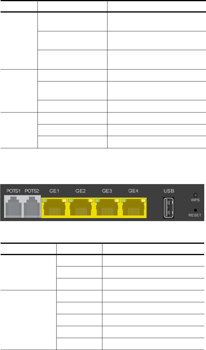
zNID 27xx series components
The zNID 27xx series indoor ONTs provide a variety of interfaces for triple
play deployments.
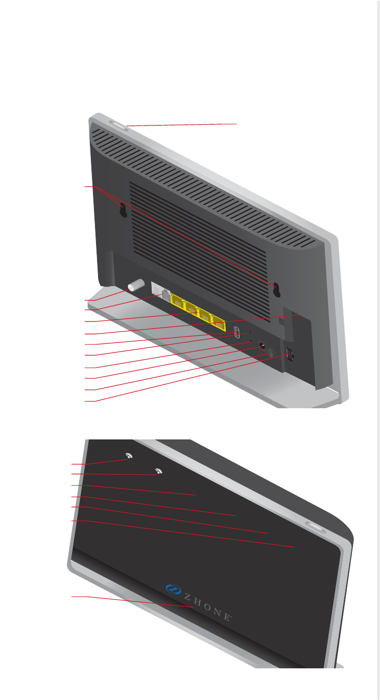
Figure 1: The interfaces and buttons on the rear of the zNID 27xx
Figure 2: The front panel indicators on the zNID 27xx series
POTS1 POTS2 GE1
VIDEO
GE2 GE3 GE4
ON/OFF
WPS
RESET
USB POWER
UPS
LED
RF Video
POTS(1-2)
GigE ports (GE1-4)
Fiber Connection
USB
WPS
RESET
POWER
ON/OFF
UPS
Holes for mounting
brackets
LED mode button
LED
5.8 2.4 VOICE INTERNET CONFIG WAN
5.8
2.4
VOICE
INTERNET
CONFIG
WAN
Logo indicator
zNID 27xx series
20 zNID 27xx Series Hardware Installation Guide
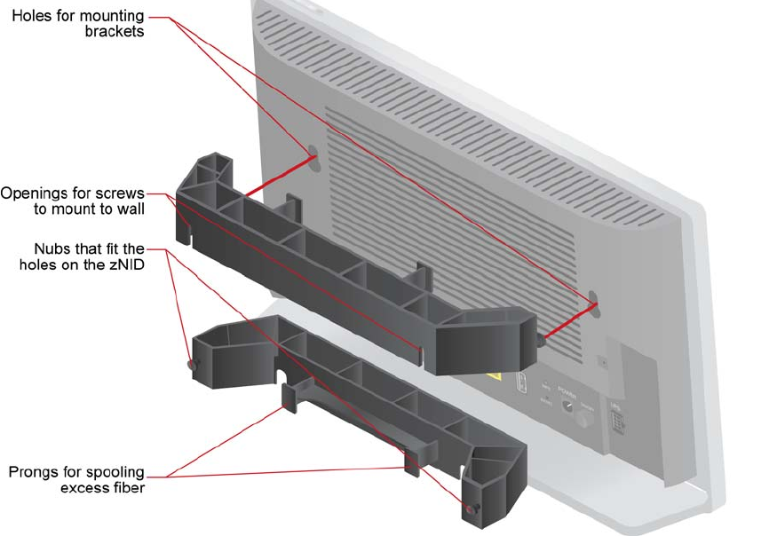
Figure 3: Wall mounting bracket features

zNID 27xx series features
zNID 27xx Series Hardware Installation Guide 21
zNID 27xx series features
Under ideal circumstances, GPON can reach up to 20 or 30 km, however the
practical limit is 12 km (about eight miles). Reach is dependent on the
configuration of the optical distribution network (ODN).
All 27xx series ONTs are designed for indoor use.
The 27xx series of zNIDs share a common SW architecture with the 24xx,
26xx, 28xx, 42xx, and 9xxx series of zNIDs, including the same intuitive Web
interface and command line interface. The zNID is also managed by the
Zhone Network Management System (ZMS), using SNMP or via OMCI
(ONT Management Control Interface). Software upgrades and configuration
backups can be handled automatically by the ZMS using the EZ Touch
management feature.
This section covers:
•zNID 27xx models
•zNID 27xx series specifications
•zNID 27xx series dimensions
The zNID enables service providers to provide voice, data, and video services
along with advanced IP and data support.

zNID 27xx series
22 zNID 27xx Series Hardware Installation Guide
zNID 27xx models
GPON models
The zNID 27xx series GPON models have the following interfaces:
Gigabit Ethernet models
The zNID 27xx series Gigabit Ethernet models have the following interfaces:
Model Description
ZNID-GPON-2726A1 GPON Uplink, 2 POTS, 4 GigE, 2x2 2.4GHz WiFi
(11b/g/n), 3x3 5GHz WiFi (11ac), USB
ZNID-GPON-2726H1 GPON Uplink, 2 POTS, 4 GigE, 2x2 2.4GHz WiFi
(11b/g/n), 3x3 5GHz WiFi (11ac), HPNA/C Coax, USB
ZNID-GPON-2727A1 GPON Uplink, 2 POTS, 4 GigE, 2x2 2.4GHz WiFi
(11b/g/n), 3x3 5GHz WiFi (11ac) USB, RF Video Coax,
USB
ZNID-GPON-2728A1 GPON Uplink, 2 POTS, 4 GigE, 3x3 2.4GHz WiFi
(11b/g/n), 4x4 5GHz WiFi (11ac), Quantenna function,
USB
Model Description
ZNID-GE-2726A1 GE Uplink, 2 POTS, 4 GigE, 2x2 2.4GHz WiFi
(11b/g/n), 3x3 5GHz WiFi (11ac), USB
ZNID-GE-2726H1 GE Uplink, 2 POTS, 4 GigE, 2x2 2.4GHz WiFi
(11b/g/n), 3x3 5GHz WiFi (11ac), HPNA/C Coax, USB
ZNID-GE-2728A1 GE Uplink, 2 POTS, 4 GigE, 3x3 2.4GHz WiFi
(11b/g/n), 4x4 5GHz WiFi (11ac), Quantenna function,
USB

zNID 27xx models
zNID 27xx Series Hardware Installation Guide 23
zNID 27xx series specifications
The possible interfaces and number of interfaces depend on the specific
model, see zNID 27xx models on page 22 for a list of models and their
interfaces.
Table 2: zNID 27xx specifications
Specifications Values
Dimensions: zNID 2726, 2727 models
•Main Body
–Height: 6.7 in (170mm)
–Width: 11.0 in (280mm)
–Thickness: 1.4 in (35mm)
•Desktop Footprint Depth
–2.4 in (60mm)
zNID 2728 model
•Main Body
–Height: 7.5 in (190mm)
–Width: 11.8 in (300mm)
–Thickness: 1.4 in (36mm)
•Desktop Footprint Depth
–2.4 in (60mm)
Weight: 28 oz (0.8 kg)
Operating temperature: •Operating Temperature: 0°C to +40°C
•Storage Temperature: -20°C to +85°C
•Relative Humidity: 0 to 95%, non-condensing
Power •12VDC, 2.0A max
•12VDC Power Supply: 100-240VAC, 50/60 Hz, 36W out
•Round barrel-type connector for power input
•2x4 Molex-type connector for optional BBU power input with alarm reporting

zNID 27xx series
24 zNID 27xx Series Hardware Installation Guide
WAN Interfaces •GPON: SC/APC connector
–Tx:
–Upstream data rate 1.25 Gbps
–1310 nm optics
–DFB transmitter
–Launch Power: +0.5 to +5 dBm
–Rx:
–Downstream data rate: 2.5 Gbps
–1490 nm optics
–APD/TIA receiver
–Receiver Sensitivity: -28 dBm
–Input power overload: -8 dBm
–Input power damage: +5 dBm
–Class B+ optics
–G.985 wavelength blocking filter
–GPON Type B redundancy support
•GE: SC/UPC connector
–1490 nm Rx (Downstream)
–Fixed SFF optics
–Tx Data Rate 1.0 Gbps
–Tx Launch Power: -2 to +8 dBm
–Rx Data Rate: 1.0 Gbps
–Rx Receiver Sensitivity: -23
–Rx Input Power Overload: -2 dBm
–1310 nm Tx (Upstream)
Table 2: zNID 27xx specifications (Continued)
Specifications Values

zNID 27xx models
zNID 27xx Series Hardware Installation Guide 25
Customer facing
interfaces (Depends on
model)
•Gig E interfaces (RJ45 - 10/100/1000Base-T Ethernet)
–Auto-MDI-X crossover control
–Auto-Speed or manual selection
•FXS POTS interfaces (RJ11)
–5 REN per line
–Battery voltage: -48VDC
–Max loop current: 40mA
–Ringing voltage: 48Vrms @ 20/25 Hz
•WiFi - 802.11b/g/n
–2.4 GHz band
–2x2 MIMO (2726, 2727) 3x3 MIMO (2728)
–Two +3dBi internal antennas (three for 2728)
–Channel width: 20 MHz, 40 MHz
–Max WiFi Connect (Phy) Rates: 54Mbps (g); 300Mbps (n)
•WiFi - 802.11ac
–5 GHz band
–3x3 MIMO (2726, 2727) 4x4 MIMO (2728)
–Three +2dBi internal antennas (four for 2728)
–Channel width: 20 MHz, 40 MHz, 80 MHz
–Max WiFi Connect (Phy) Rate: 1.3 Gbps
•RF Video Output Port (F-Type coaxial connector)
–RF output impedance: 75 ohms
–RF passband: 47 to 1000 MHz
–RF output level: 17 dBmv minimum (550 MHz, 3.5% OMI per channel)
•RF Video Rx
–1550nm optics
–Usable input power range: -8 dBm to +2 dBm
–Input power overload: +2 dBm
–Input damage level: +5 dBm
•USB
–USB 2.0 port
–3G dongle support for uplink fallback
Table 2: zNID 27xx specifications (Continued)
Specifications Values

zNID 27xx series
26 zNID 27xx Series Hardware Installation Guide
Wireless Support •SSIDs: Up to 8
•Max number of subscribers: 64
•Max Tx power: 250 mW (US models)
•Max Tx power: 100-200 mW (other models)
•Authentication Security: WEP, WPA-PSK, WPA2, WPA2-PSK, 802.1x
•WEP (64-bit, 128-bit), AES, TKIP+AES
•WPS modes: push-button, API PIN, STA PIN
•RADIUS Server support
•MAC address filtering
•Access Point and Wireless Bridge modes
Voice Support •SIP (RFC 3261)
•SIP-PLAR
•MGCP
•Codec: G.711 (u-law and A-law), G.729B, G726
•DTMF dialing
•5 REN (total) per ONT
•Echo cancellation
•Voice Activity Detection (VAD), Comfort Noise Insertion (CNI)
•Caller ID, Call Waiting, Call Forwarding, Call Transfer, Three Way Calling,
Distinctive Ringing.
•G.711 fallback for FAX
•T.30 and T.38 Fax
•DHCP client or static IP configuration
Standards Support •ITU-T G.984 compliant
•IEEE 802.3 Ethernet
•IEEE 802.1p/q VLANs
•IEEE 802.3u Fast Ethernet
•IEEE 802.3ab 1000Base-T
Table 2: zNID 27xx specifications (Continued)
Specifications Values

zNID 27xx models
zNID 27xx Series Hardware Installation Guide 27
Protocol Support •GPON uplink
–Fully ITU-T G.984 compliant framing
–32 T-CONTs per device
–32 GEM Ports per device
–
1:1 mapping of GEM ports into T-CONTS with priority queue based scheduling
–Activation with automatic discovered SN and password in conformance
with ITU-T G.984.3
–
Mapping of GEM Ports into a T-CONT with priority queues based scheduling
–AES-128 Decryption with key generation and switching
–802.1p mapper service profile on U/S
–Support for Multicast GEM Port
–FEC (Forward Error Correction)
–Dying Gasp support
•QoS
–Ethernet bridging/switching per IEEE802.1d/802.1q
–Traffic shaping – bandwidth management and rate limiting
–QoS with support for IEEE 802.1p + DSCP VLANs
•VLANs
–Per port IEEE 802.1q VLAN ID processing
–All VLAN IDs supported
–VLAN tagging/untagging
–VLAN Stacking (QinQ)
–VLAN Switching
•IPTV
–IGMP v3 Snooping
–VLAN support
Bridging, ISO Layer 2 •802.3n flow control
•Automatic MAC learning and aging
•Unlimited # of MAC addresses for OMCI-configured flows (GPON only)
•Support for up to 4,096 MAC addresses for RG traffic flows
•Broadcast storm control
•LLDP-MED
Table 2: zNID 27xx specifications (Continued)
Specifications Values

zNID 27xx series
28 zNID 27xx Series Hardware Installation Guide
IP Routing and Firewall •PPPoE
•NAT/NAPT
•port forwarding
•DHCP server
•DNS Proxy
•UPnP
IPv6 •IPv4 and IPv6 Dual-Stack-lite
•Bridged Mode (transparent pass-thru of IPv6 frames)
•IPv6 Support for BRouted, and PPPoE-Bridged VLANs
•DHCPv6 client and server
•Router Advertisement on LAN- side interfaces of BRouted and
PPPoE-Bridged VLANs
•SLAAC for automatic acquisition of WAN-side IPv6 address and Gateway
•CLI and HTTP management via IPv6 address
•TR-069 management via IPv6 address
Management •Zhone Management System (ZMS)
–EZ Touch
–CPE Manager
•USP (Unified Service Provisioning)
•OMCI (GPON only)
•Web UI
•Command Line Interface (CLI)
•SNMP
•TR-069
Regulatory Compliance •CE
•UL/CSA
•FCC Part B
•21 CFR 1040.10, 1040.11
•RoHS 2011/65/EU
Table 2: zNID 27xx specifications (Continued)
Specifications Values

zNID 27xx series dimensions
zNID 27xx Series Hardware Installation Guide 29
zNID 27xx series dimensions
Figure 4: zNID 2726, 2727 dimensions
Figure 5: zNID 2728 dimensions

zNID 27xx series
30 zNID 27xx Series Hardware Installation Guide
zNID 27xx series indicators
The indicators vary depending on the model of zNID. See zNID 27xx models
on page 22 for a complete list of zNID models.
Front panel indicators
A momentary push-button switch on the top edge of the ONT towards the
right side of the unit (when viewed from the front) that allows the operator
reduce the number of indicators displayed when less lighting disturbance is
desired.
Figure 6: zNID 27xx LED Mode Switch on top edge
Pressing and holding this switch for 2-3 seconds will change the LED
indicator mode from Mode 1 to Mode 2, or from Mode 2 to Mode 3, or from
Mode 3 back to Mode 1. The three modes are:
•Day Mode — normal mode — all Indicators are enabled
•Night Mode — only INTERNET, VOICE and LOGO Indicators are
enabled
•Off Mode — all Indicators are disabled
Note that the selected indicator mode is stored in a special portion of
non-volatile memory and is retained over a reboot, power cycle, or reset to
Factory Defaults.
Table 3: LED indicator modes
Indicator Mode 1 (Day) Mode 2 (Night) Mode 3 (Off)
Logo Enabled Enabled Disabled
WAN Enabled Disabled Disabled
CONFIG Enabled Disabled Disabled
INTERNET Enabled Enabled Disabled
VOICE Enabled Enabled Disabled
2.4 Enabled Disabled Disabled
5.8 Enabled Disabled Disabled
zNID 27xx series indicators
zNID 27xx Series Hardware Installation Guide 31
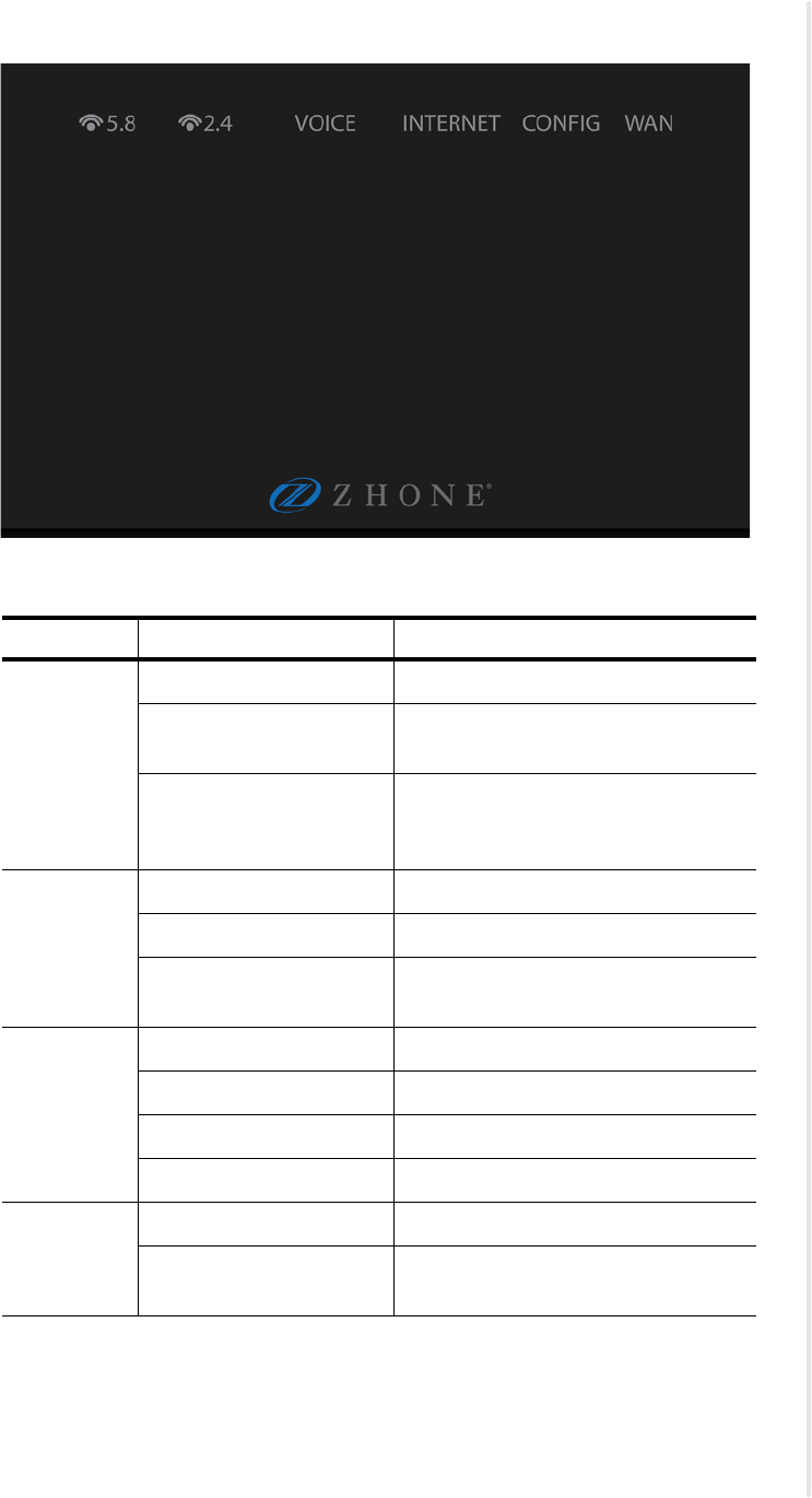
Figure 7: zNID 27xx front panel indicators
Table 4: zNID-GPON-27xx indicators
Indicator Behavior Indicates
Logo Steady on ONT is powered on and ready for use.
Blinking (1/sec) ONT is powered on but not yet ready
for use.
Off ON/OFF Switch is Off, or no power
supply connected, or power supply not
plugged in.
WAN Steady on Ranged successfully
Slow blink (1/sec) Ranging in progress
Off Not ready for ranging or not
provisioned
CONFIG Steady on OMCI provisioning is complete
Rapid blink (10/sec) OMCI provisioning is in progress
Blinking (1/sec) SNMP provisioning in progress.
Off No OMCI provisioning
INTERNET Steady on Internet service is available.
Off Internet service is unavailable (no
response from DNS server).
zNID 27xx series
32 zNID 27xx Series Hardware Installation Guide
Ethernet interface LEDs
Figure 8: zNID 27xx Ethernet interface LEDS
VOICE Steady on VoIP Registration successfully
completed.
Blinking (1/sec) At least one attached phone is
off-hook.
Off No calls active, no phones are
off-hook.
2.4 Steady on WiFi service is enabled on ONT.
Blinking (1 per sec) WiFi data passing between ONT and
connected device.
Off WiFi service is disabled on ONT.
5.8 Steady on WPS pairing completed successfully.
Blinking (1 per sec) WPS pairing in progress.
Off WPS is disabled on ONT.
Table 4: zNID-GPON-27xx indicators
Indicator Behavior Indicates
Table 5: zNID 27xx Ethernet interface LEDs
LED Name Color/Behavior Indicates
Right LED
(SPEED) Off 10 BaseT
Yellow 100 BaseT
Green 1000 BaseT
Left LED
(LINK/ACTIVITY)
Off Link Down or Port Disabled
Solid yellow Link up, no activity
Blinking yellow Link up and activity
Solid green Link up, no activity, power present
Blinking green Link up, activity and power present
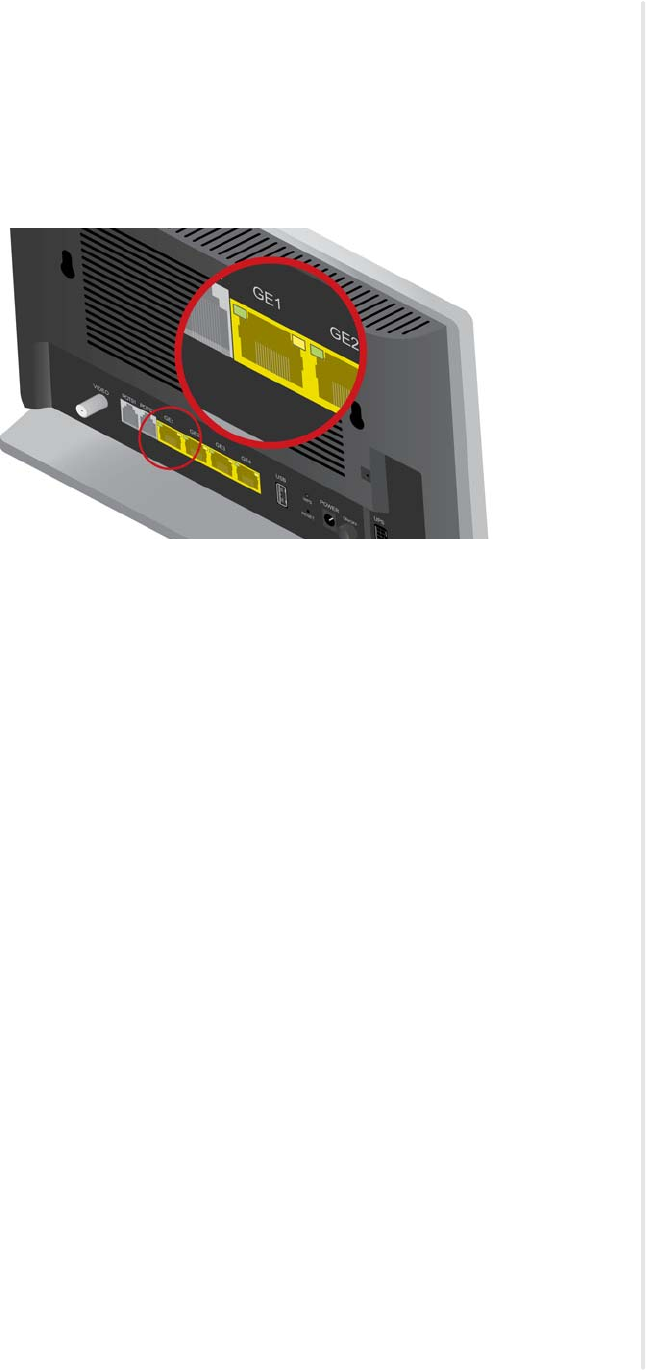
Logging in to the 27xx series zNID
zNID 27xx Series Hardware Installation Guide 33
Logging in to the 27xx series zNID
The zNID 27xx series may be managed locally using Web UI or CLI. This
section describes logging into the zNID locally using the subscriber facing
LAN port, GE1.
Figure 9: Log into GE port 1 to reach the Web UI or CLI on the zNID
To login with a browser:
1Connect an Ethernet cable from your computer to GE1 on the zNID.
2Launch a browser and point it to 192.168.1.1.
3Enter the username and password.
The default username/password is admin/zhone.
To login with a telnet session:
1Connect an Ethernet cable from your computer to LAN1 on the zNID
2Launch a telnet session and point it to 192.168.1.1.
3Enter the username and password.
The default username/password is admin/zhone.
zNID 27xx series
34 zNID 27xx Series Hardware Installation Guide

zNID 27xx Series Hardware Installation Guide 35
ZNID 27XX INSTALLATION
This chapter can be used as separate installation instructions. This chapter
explains how to unpack the zNID 27xx and install the zNID 27xx hardware.
It includes the following sections:
•Install the zNID 27xx, page 35
•Overview of zNID 27xx series installation, page 36
Install the zNID 27xx
This section describes the procedures for installing the zNID. The overiew
procedure provides options for wall mounting or placing the zNID on a
surface with or without the optional fiber tray.
This section contains the following topics:
•Overview of zNID 27xx series installation on page 36
•Installation precautions on page 37
•Mount the zNID on page 38
•Manage the optical cable on page 42
•Fiber handling on page 42
•Testing optical power on page 42
•Optical fiber cable placement with the zNID mounting bracket on page 43
•Connect to network on page 44
•Connect power on page 46
•Connecting phone terminals on page 47
•Connecting Ethernet ports on page 48
•Complete the zNID installation on page 50
zNID 27xx Installation
36 zNID 27xx Series Hardware Installation Guide
Overview of zNID 27xx series installation
1Select the location
Ensure that the environment is free of dust and excessive moisture and
has sufficient ventilation.
The zNID may be installedon a desktop. The zNID should be placed in a
clean dry place as is appropriate for electronic equipment
Installation precautions on page 37
Install the system in reasonable proximity to all equipment or rooms
where the TV or computer reside for straightforward connections.
2Mount the zNID.
Mount the zNID on page 38
3Install service fiber to the zNID.
Connect to network on page 44
4Connect AC power and/or UPS
Connect power on page 46
5Connect the subscriber facing services
aConnect telephone (POTS) service
See Connecting POTS on page 47.
bConnect Ethernet service
See Connect Ethernet ports on page 48.
cConnect Video service
See Connect RF coaxial port on page 49.
6Complete
Checking the indicators on page 50

Installation precautions
zNID 27xx Series Hardware Installation Guide 37
Installation precautions
Maximum operating temperature should not exceed the range of 0° C to 40° C
(32° F to 104° F).
Ensure that proper cable grades are used for all system and network
connections. For best results, use the cables and connectors recommended in
this document.
Connect the system to the power supply circuit as described in this document.
Before making fiber connections, be sure that the optical cable fiber tips and
components are clean and free of dust and debris. Follow established cleaning
procedures if required.
Note: Sharp bends in fiber cables create undesirable optical
attenuation or loss. The zNID fiber tray provides fiber spools and
hooks to avoid sharp bends in the fiber cable. A minimum bend radius
of 30 mm (1.2 in) is recommended for stripped fiber.
La température maximum de fonctionnement ne doit pas dépasser le plage de
0° C à 40° C (32° F à 140° F).
Assurez-vous que les rangs de câbles corrects sont utilisés pour tous les
raccordements du système et du réseau. Pour les meilleurs résultats, utilisez
les câbles et connecteurs recommandés dans ce document.
Raccordez le système au circuit d'alimentation comme décrit dans ce
document.
Avant de réaliser les raccordements des fibres, soyez sur que les embouts de
fibre des câbles optiques et les composants sont propres et libres de poussière
et autres débris. Suivez les procédures de nettoyage établies si nécessaire.
Note: Remarque : Les courbes serrées dans les câbles optiques
créent une atténuation ou une perte optique indésirable. Le plateau de
fibres zNID fournit des bobines et des crochets de fibre afin d'éviter
les courbes serrées dans le câble optique. Un rayon de courbure
minimum de 30 mm (1,2 po) est recommandé pour la fibre dénudée.
zNID 27xx Installation
38 zNID 27xx Series Hardware Installation Guide
Mount the zNID
The zNID enclosure can be mounted on a vertical surface (wall) or placed on
a horizontal surface such as a desktop or shelf.
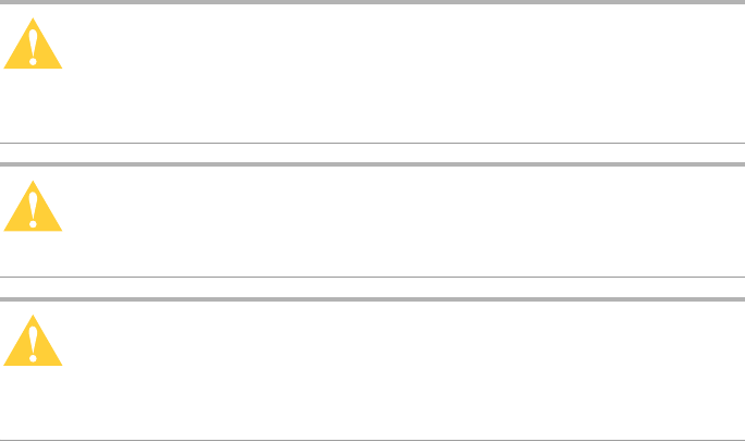
Caution: To prevent damage to the enclosure, use screws
appropriate to the mounting surface.
Précaution : Afin d'éviter d'endommager l'enceinte, utilisez des vis
adaptées à la surface de montage.
Caution: Install the zNID fiber tray a proper height from the floor.
Précaution : Installez le plateau de fibres zNID à une hauteur
correcte par rapport au sol.
Caution: The zNID should always be mounted in a vertical
orientation.
Précaution : Le zNID doit toujours être monté en orientation
verticale.
Mount the zNID
zNID 27xx Series Hardware Installation Guide 39
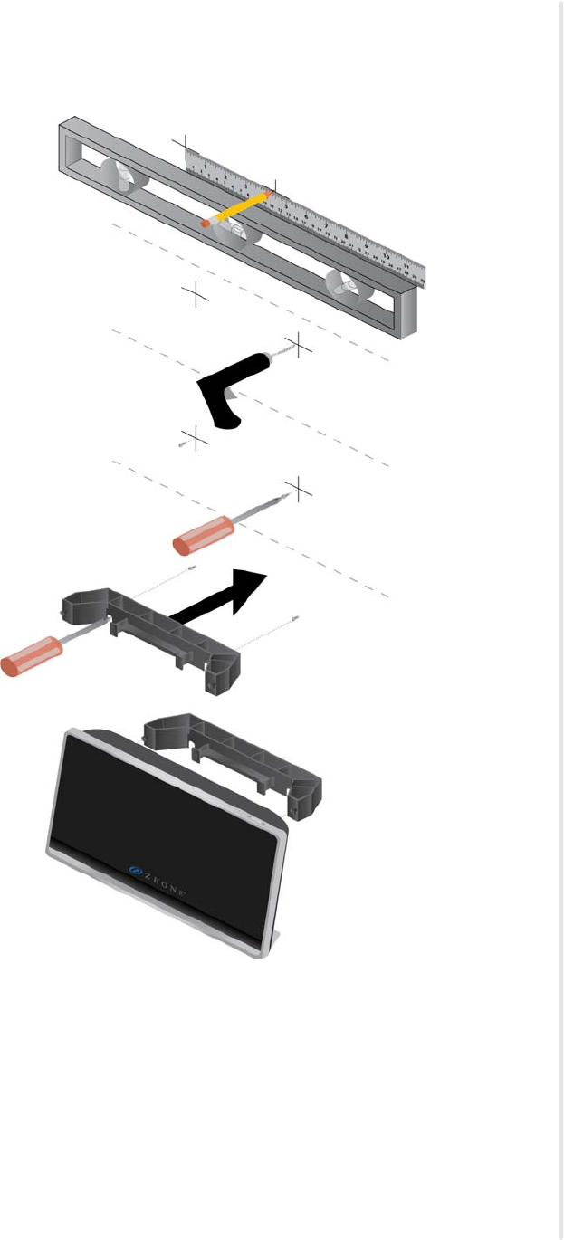
Mounting the zNID with the wall mount
Figure 10: Installing the 27xx ONT on a wall
To mount the zNID 27xx directly on a wall:
1Prepare the surface for mounting.
zNID 27xx Installation
40 zNID 27xx Series Hardware Installation Guide
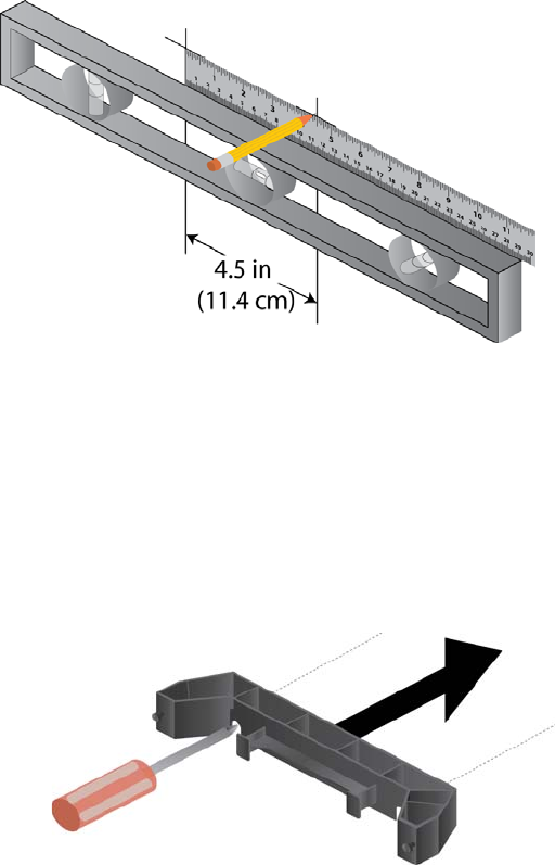
2Mark the hole positions.
The holes for the fiber tray are 17.4 cm apart (about 6 7/8 inches) on the
horizontal axis.
Figure 11: Mark on a level line
3Drill the holes.
4Attach the screws, leaving enough of the screw to slide on the mounting
bracket.
Use screws appropriate for the type of surface to which the unit is
mounted (i.e. wood, brick, CB, etc.).
5Put the mount on the screws, then tighten the screws.
Figure 12: Attach the mount to the screws, then lightly tighten the screws.
The screws should leave enough space from being flush with the wall for
the zNID legs to hold the unit firmly against the wall.
Mount the zNID
zNID 27xx Series Hardware Installation Guide 41
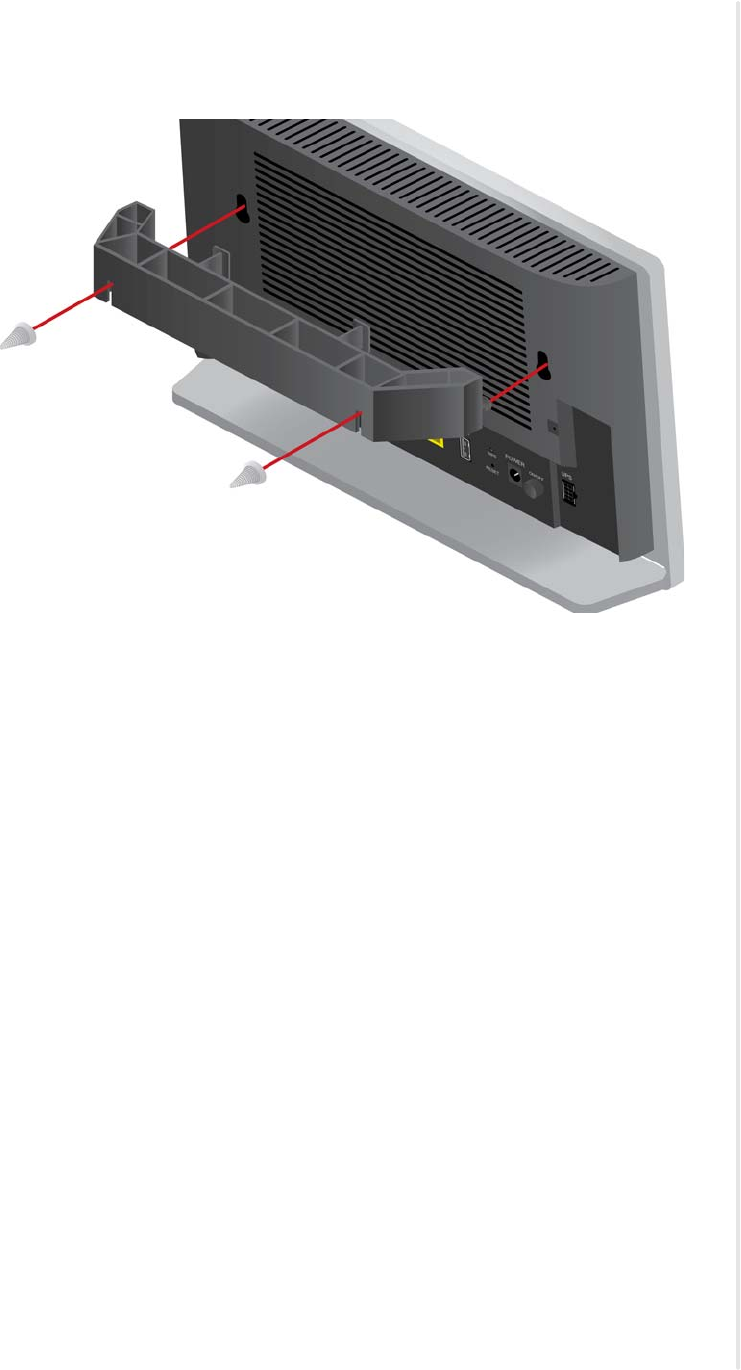
6Attach the zNID to the nubs on the wall mount.
Figure 13: Attach the zNID to the wall mount
Note that the wall mount includes two prongs for wrapping fiber.

zNID 27xx Installation
42 zNID 27xx Series Hardware Installation Guide
Manage the optical cable
When making a fiber optic connection, avoid touching the fiber cable ends to
the outside of the mating connector. Touching can contaminate the
connectors.
Fiber handling
Before making any connections, be sure that the optical cable fiber tips and
components are clean and free of dust and debris.
The zNID fiber tray provides fiber spools and hooks to avoid sharp bends in
the fiber cable. A minimum bend radius of 30 mm is recommended for
stripped fiber and larger fiber needs a larger bend radius to guarantee the
specified system performance.
Note: Sharp bends in fiber cables create undesirable optical
attenuation or loss.
Testing optical power
Table 6 specifies how much laser power to expect on the fiber.
Table 6: Optical values for zNID-GPON-27xx
Parameter 1490 nm
(Data Downstream) 1550 nm
(RF Downstream)
Damage Level +5 dBm +5 dBm
Optical Overload -8 dBm +2 dBm
Maximum Usable — +2 dBm
Minimal Optical Signal -28 dBm -8 dBm
Mid Range Optical Value -17 dBm -4 dBm
Table 7: Optical values for zNID-GE-27xx
Parameter Active Ethernet
Damage Level +5 dBm
Optical Overload -2 dBm
Minimal Optical Signal -23 dBm
Mid Range Optical Value -12 dBm
Optical fiber cable placement with the zNID mounting bracket
zNID 27xx Series Hardware Installation Guide 43
Optical fiber cable placement with the zNID mounting bracket
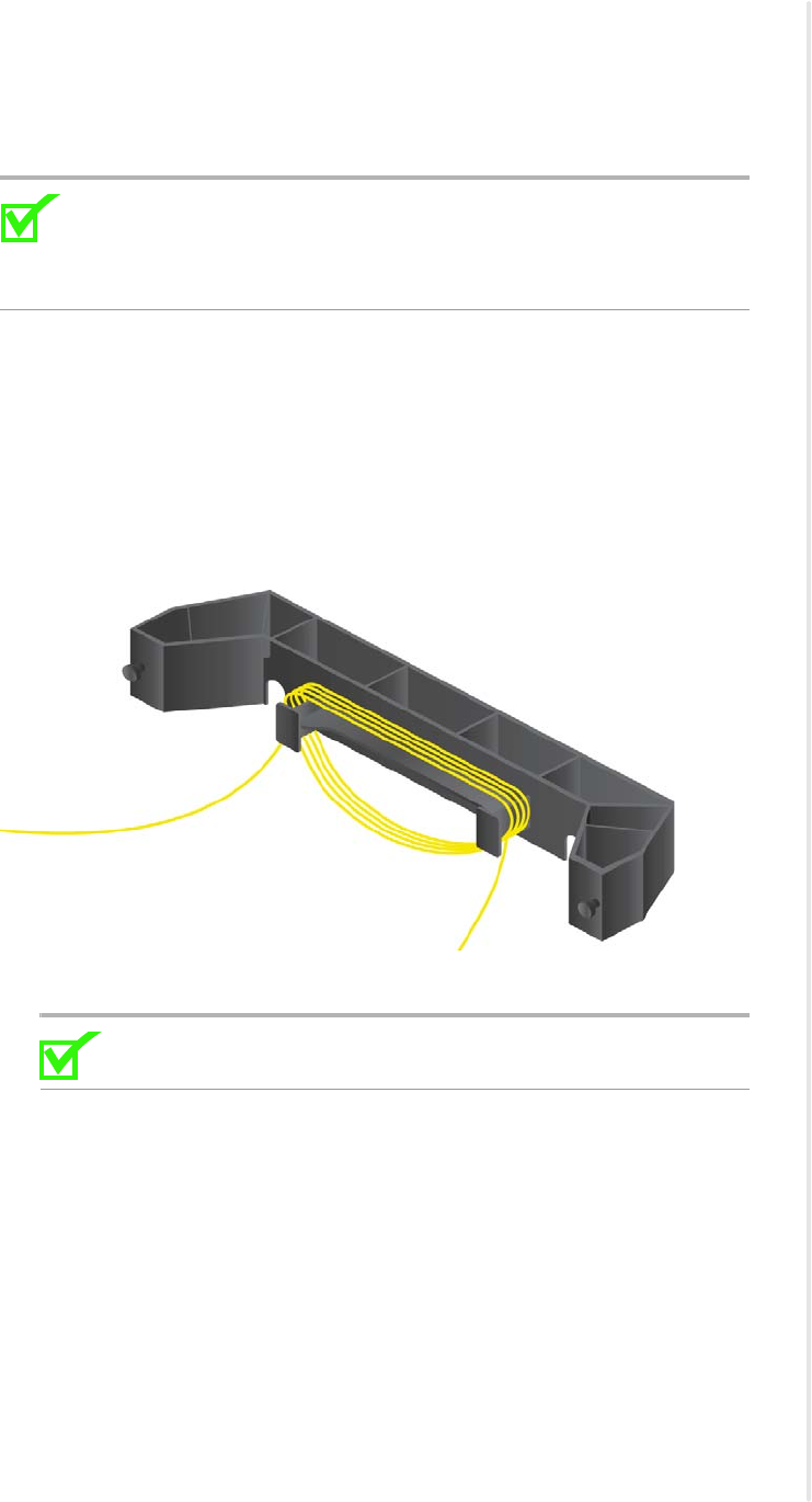
Using a fiber tray involves routing the optical fiber around the prongs, then
physically to the SC connector in the zNID 27xx .
Note: Sharp bends in fiber cables create undesirable optical
attenuation or loss. The zNID enclosure provides fiber spools and
hooks to avoid sharp bends in the fiber cable. A minimum bend radius
of 30 mm (1.2 in) is recommended for stripped fiber.
To place the fiber cable in the fiber tray:
1Inspect and clean the fiber connector to ensure it is free of impurities.
2Make sure the fiber segment is properly installed in the fiber tray, excess
cable is wrapped around fiber reels without having improper bends
leaving enough loose cable so that it will not take too sharp of a bend to
connect to the zNID.
Figure 14: Maintain the proper bend radius in the fiber
3Test the fiber cable to verify clean signals.
Note: It is recommended that the fiber cable be tested before
finishing.
zNID 27xx Installation
44 zNID 27xx Series Hardware Installation Guide
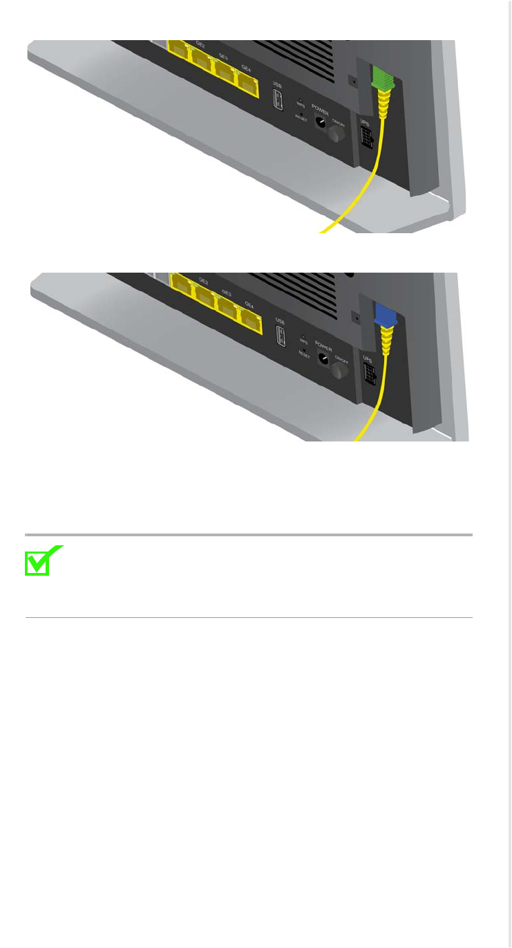
Connect to network
Connecting the SC connectors
Connect the SC connector from the electronics module to the SC connector in
the zNID enclosure.
Observe the necessary precautions to decrease the risk of exposure to laser radiation.
WARNING! Risk of eye damage. At all times when handling
optical fibers, follow the safety procedures recommended by your
company.
AVERTISSEMENT ! Risque de blessure aux yeux. Lors de la
manipulation de fibres optiques, suivez en permanence les
procédures de sécurité recommandées par votre société.
Although Zhone optical products have a Class I certification, hazardous
exposure to laser radiation can occur when fibers are connected, disconnected
or broken. Handling of optical fibers without dust caps increases the risk of
exposure. Exposure to either visible or invisible laser light can damage your
eyes under certain conditions.
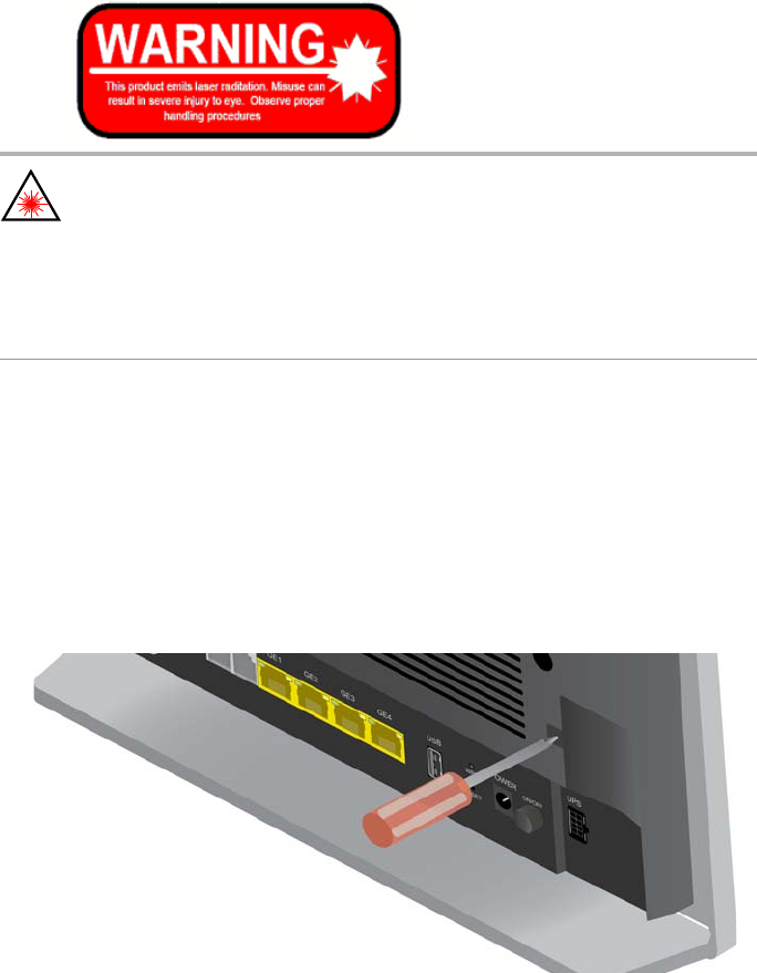
1Remove the fiber service cover by removing the fiber service screw and
then pull the fiber service cover forward.
Figure 15: Fiber service cover
Connect to network
zNID 27xx Series Hardware Installation Guide 45
Figure 16: zNID-GPON-27xx models use SC/APC connector (green)
Figure 17: zNID-GE-27xx models use SC/UPC connector (blue)
2Remove the dust covers from the SC optical connectors.
Clean the connector if necessary.
3Plug in the fiber connector to connect the zNID to the network.
Note: To function properly the optical strength to the zNID
should be with the limits shown in Optical values for
zNID-GPON-27xx or Optical values for zNID-GE-27xx on
page 42.
4Reattach the fiber service cover onto the zNID including the fiber service screw.
zNID 27xx Installation
46 zNID 27xx Series Hardware Installation Guide
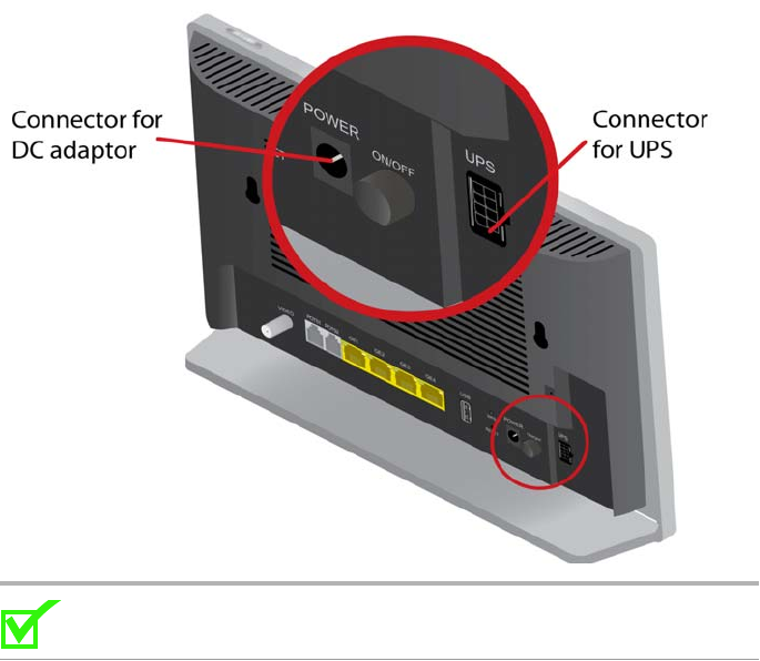
Connect power
The zNID is powered by 12VDC using the power supply which is shipped
with the unit. An optional uninterruptable power supply may also be used.
The zNID 27xx has a round power port that accepts the barrel connector of
the 12VDC power supply, and a UPS input port for connecting to a BBU.
Figure 18: The zNID 27xx power connections
Note: The Power input and the UPS input must not be used at the
same time.
For pinout information for the UPS connector, see UPS pinouts and alarms on
page 58.
Connecting phone terminals
zNID 27xx Series Hardware Installation Guide 47
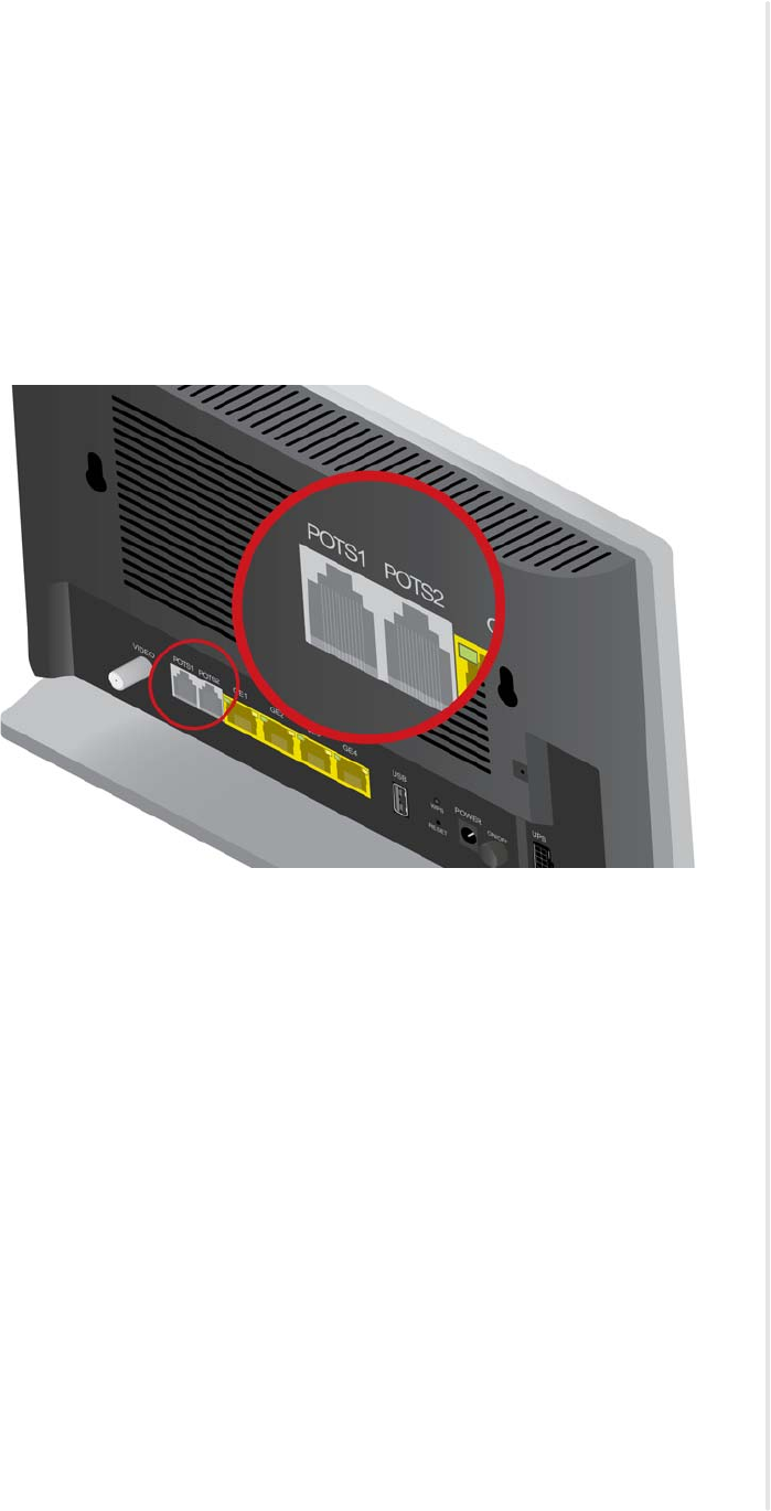
Connecting phone terminals
Connecting POTS
The zNID 27xx models have the ability to connect POTS via RJ-11
connector.
The terminal connections are shown in Figure 19.
1Locate the subscriber’s telephone wire pair.
Figure 19: Connect phone lines
2If the wire pair is not terminated, follow local practices to attach an RJ-11
connector.
3Plug the wire pair with RJ-11 connector into one of the zNID RJ-11 phone
jacks.
4Repeat steps 1-3 as needed to connect additional phone lines.
For pinout information for the POTS connector, see POTS pinouts on page 52.
zNID 27xx Installation
48 zNID 27xx Series Hardware Installation Guide
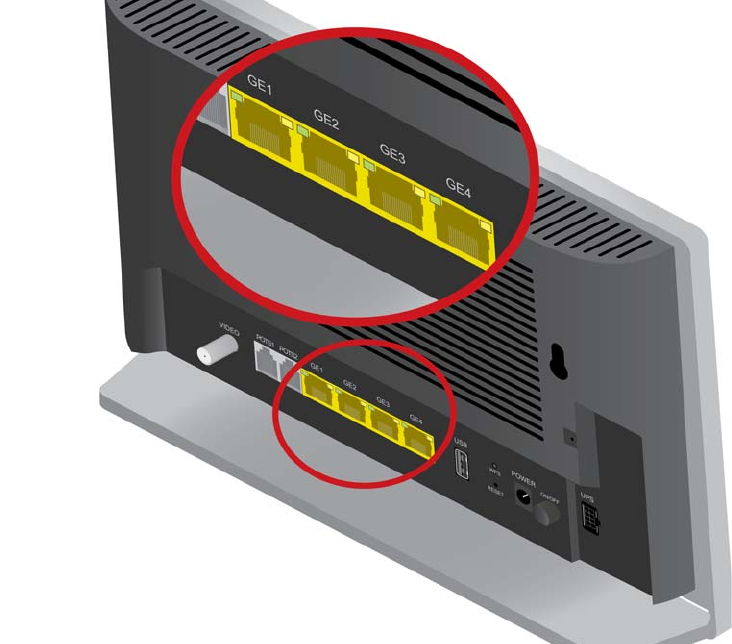
Connecting Ethernet ports
The zNID provides RJ-45 eight-pin modular jacks.
Connect Ethernet ports
The zNID provides RJ eight pin modular jacks (RJ45) for Ethernet
connections. Ethernet connections can be used to deliver any packet services
including IPTV, data, and VoIP.
For Ethernet services, connect a Category 5 or a Category 6 cable to an RJ45
interface as shown in Figure 20.
1Locate the Ethernet LAN cable.
2If the cable is not terminated, follow local practices to attach an RJ-45
connector.
3Plug the Ethernet cable into the appropriate RJ-45 Ethernet port.
Figure 20: The RJ-45 Ethernet ports.
4Repeat steps 1-3 as needed to connect additional Ethernet cables.
For pinout information for the Gigabit Ethernet connector, see Gigabit
Ethernet pinouts on page 51.
Connecting RF video coaxial port
zNID 27xx Series Hardware Installation Guide 49
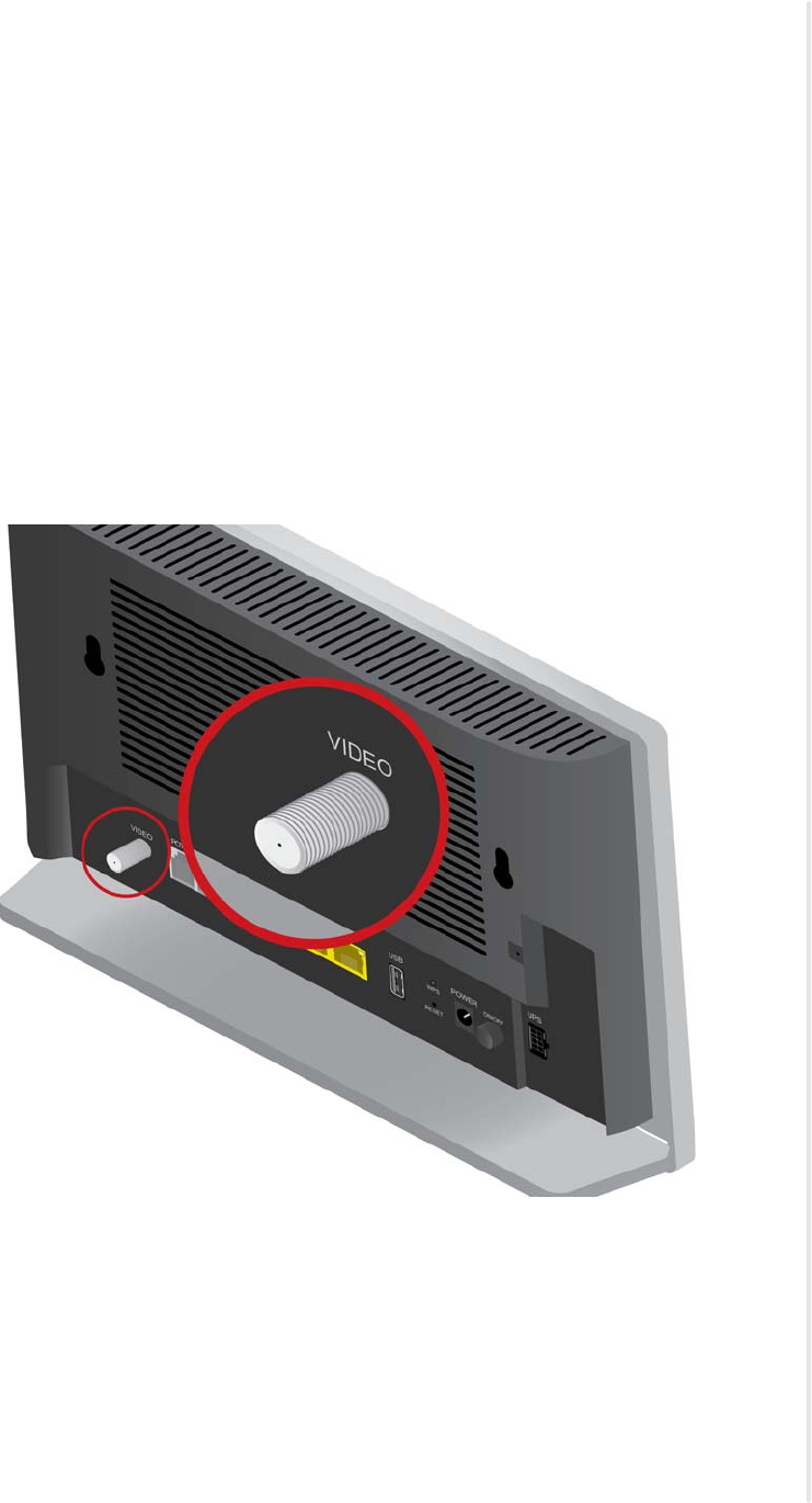
Connecting RF video coaxial port
Connect RF coaxial port
Some models of the zNID provide a coaxial connector for RF video
connections.
For RF video, connect a coaxial cable as shown in Figure 21.
1Locate the premises’ coaxial cable.
2If the cable is not terminated, follow local practices to attach a coaxial
connector.
3Screw the coaxial connector to the VIDEO coaxial port and tighten by
hand.
Figure 21: The coaxial video port.
zNID 27xx Installation
50 zNID 27xx Series Hardware Installation Guide
Complete the zNID installation
After making the physical connections, complete the installation by checking
the indicators.
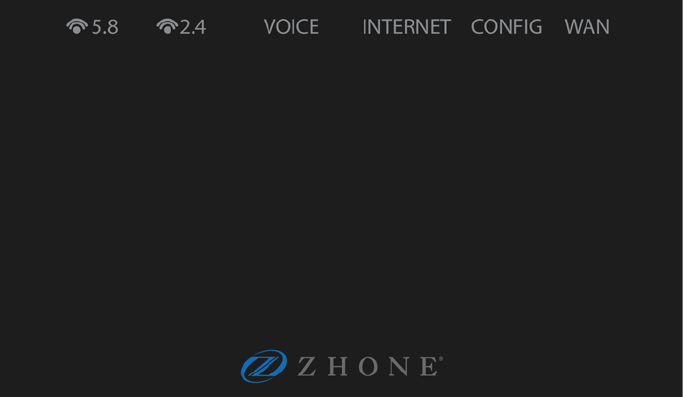
Checking the indicators
Check the logo indicator to verify that power is working.
Figure 22: Front of the zNID. The logo is also an indicator
The logo is an indicator that the unit is powered on and ready for use. For
more information, see the zNID 27xx series indicators on page 30.
zNID 27xx Series Hardware Installation Guide 51
APPENDIX: PINOUTS
This appendix provides the following pinouts
•Gigabit Ethernet pinouts on page 51
•POTS pinouts on page 52
•UPS pinouts and alarms on page 53
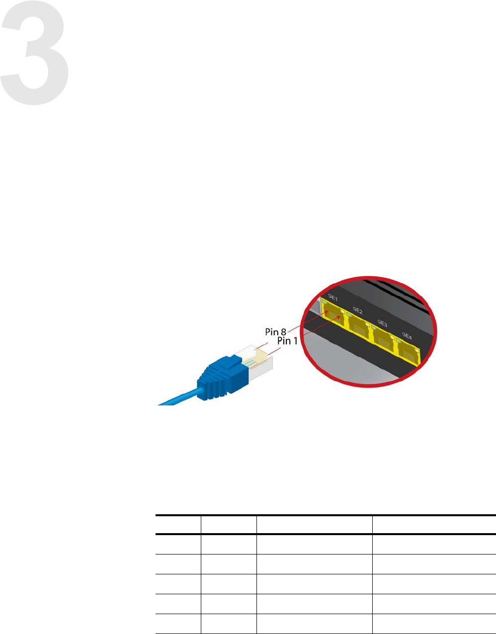
Gigabit Ethernet pinouts
Figure 23: The Gigabit Ethernet ports use an RJ45 connector
The PoE zNID 27xx models are considered a “PSE Endspan” devices,
integrating data and power on the same wires following the IEEE 802.3af (at)
'Alternative A' pinout, which is the industry standard for “active” PoE.
Note that other than the PoE power variation, the pinouts for PoE and
non-PoE Ethernet ports is the same.
Table 8: Pinout for the GigE RJ45
Pin Name Description For PoE Models
1 TX_D1+ Transceive data + Vport Positive (pair 1)
2 TX_D1- Transceive data - Vport Positive (pair 1)
3 RX_D2+ Recieve data + Vport Negative (pair 2)
4 BI_D3+ Bi-directional data +
5 BI_D3- Bi-directional data -
Appendix: Pinouts
52 zNID 27xx Series Hardware Installation Guide
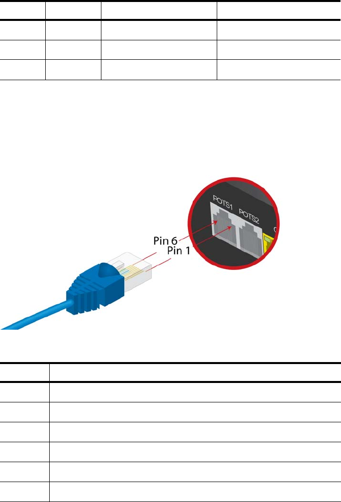
POTS pinouts
Figure 24: The POTS ports use an RJ11 connector
6 RX_D2- Receive data - Vport Negative (pair 2)
7 BI_D4+ Bi-directional data +
8 BI_D4- Bi-directional data -
Table 8: Pinout for the GigE RJ45
Pin Name Description For PoE Models
Table 9: Pinout for the POTS RJ11
Pin Description
1N/C
2Tip2
3 Ring1
4Tip1
5 Ring2
6N/C
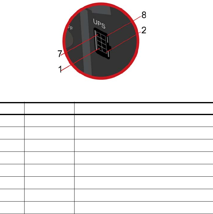
UPS pinouts and alarms
zNID 27xx Series Hardware Installation Guide 53
UPS pinouts and alarms
Figure 25: Pin out layout for the UPS connector
Table 10: Pin out descriptions for the UPS connection
Pin Signal Alarm description/Comments
1+12V UPS in
2 GND UPS return. Connected to Signal GND on ONT
3 On battery Open signal when on battery power
4 Signal return Connected to Signal GND on ONT
5 Missing battery Open signal when battery not detected
6 Replace battery Open signal when battery should be replaced
7 GND Connected to Signal GND on ONT
8 Low Battery Open signal when battery is low
Appendix: Pinouts
54 zNID 27xx Series Hardware Installation Guide

Index
56 zNID 27xx Series Hardware Installation Guide