DASAN Zhone Solutions SZ045N5G-A Point-to-Point UNII wireless transport User Manual

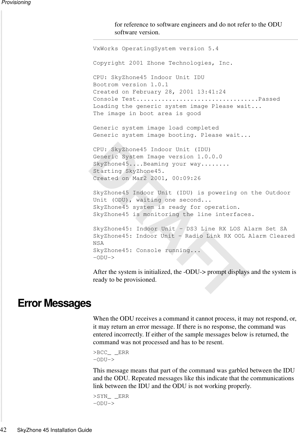
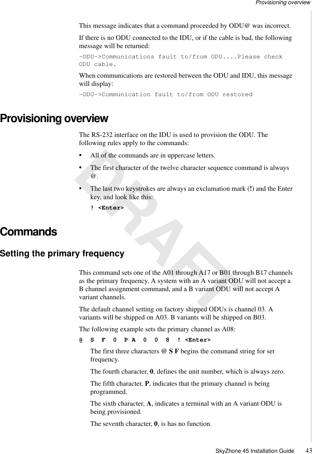
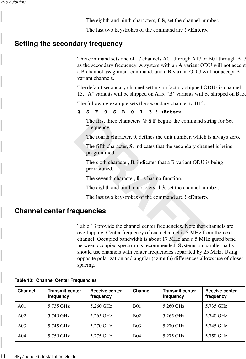
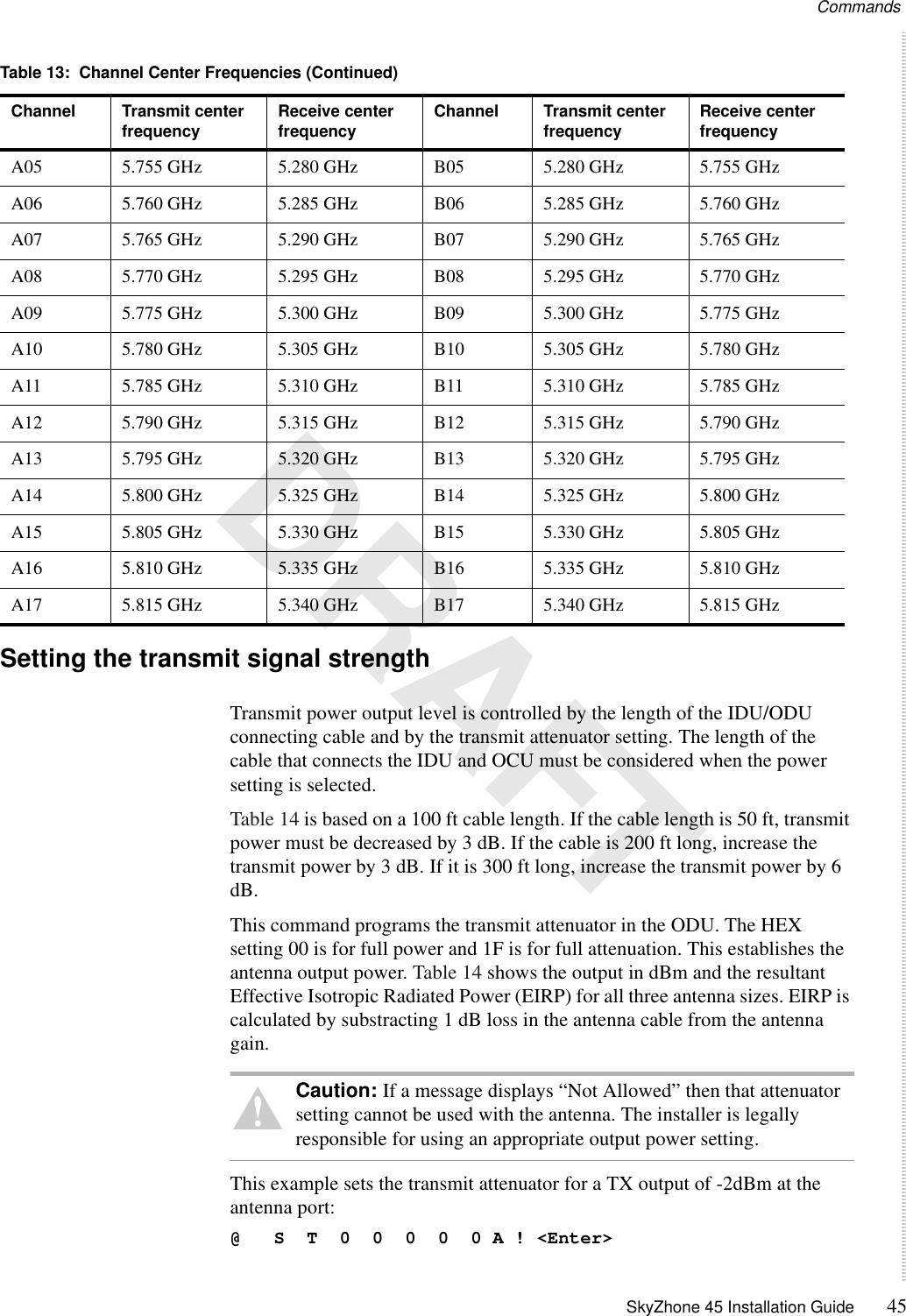
Zhone Technologies, Inc. Point-to-Point UNII wireless transport

Users Manual

 SKYZHONE 45 INSTALLATION GUIDEFor software version  (ODU) 1.0.4
2SkyZhone 45 Installation Guide DRAFTModel Number: Generic System Image Version 1.0.0.2Document Part Number:  xxx-xxxxx-xxZhone Technologies@Zhone Way7001 Oakport StreetOakland, CA 94621USA510.777.7000www.zhone.comEmail: info@zhone.comCOPYRIGHT ©2000-2001 Zhone Technologies. All rights reserved.This publication is protected by copyright law. No part of this publication may be copied or distributed, transmitted, transcribed, stored in a retrieval system, or translated into any human or computer language in any form or by any means, electronic, mechanical, magnetic, manual or otherwise, or disclosed to third parties without the express written permission from Zhone Technologies.Z-Plex, Z-Edge, ZMS, BAN, SLMS, SkyZhone and Sechtor are trademarks of Zhone Technologies, Inc.Zhone and the Zhone logo are registered trademarks of Zhone Technologies.All other trademarks and registered trademarks are the property of their respective holders.Zhone Technologies makes no representation or warranties with respect to the contents hereof and specifically disclaims any implied warranties of merchantability, noninfringement, or fitness for a particular purpose. Further, Zhone Technologies reserves the right to revise this publication and to make changes from time to time in the contents hereof without obligation of Zhone Technologies to notify any person of such revision or changes.
 DRAFTFederal Communications Commission (FCC)Part 15 RegulationThis equipment has been tested and found to comply with the limits for a Class A digital device, pursuant to part 15, subpart B, of the FCC rules. These limits are designed to provide reasonable protection against harmful interference when the equipment is operated in a commercial environment. This equipment generates, uses, and can radiate radio frequency energy and, if not installed and used in accordance with the user manual, may increase the potential for harmful interference to radio communications. Operation of this equipment in a residential area is likely to cause harmful interference, in which case the user will be required to correct the interference at his own expense.No modifications or changes to this equipment are allowed, unless the changes or modifications are expressly approved by the manufacturer.It is recommended that shielded cables be used to reduce interference whenever interference is suspected.
4SkyZhone 45 Installation Guide DRAFT
SkyZhone 45 Installation Guide 5 DRAFTCONTENTSFederal Communications Commission (FCC)Part 15 Regulation ...............................................................................................3About This Guide...............................................................................................................................9Notes, cautions, and warnings ...............................................................................9Chapter 1 Overview....................................................................................................................11System overview.......................................................................................................11System hardware.....................................................................................................11Indoor Unit.......................................................................................................12Outdoor units....................................................................................................12ODU interior LEDs ..........................................................................................13Antenna and cable ............................................................................................13Technical specifications.........................................................................................14Chapter 2 Preparing for Installation ...................................................................................19Site selection requirements...................................................................................19Antenna path guidelines.........................................................................................19Received Signal Level and link budget ..............................................................20Fade margin calculations.......................................................................................21Unit Frequencies.......................................................................................................21Powering the units ...................................................................................................21Equipment ..................................................................................................................22Hardware included with SkyZhone 45 system .......................................................22Customer-supplied hardware ..................................................................................22Installation contractor-supplied hardware...............................................................22Required tools.........................................................................................................23Chapter 3 Installation................................................................................................................25Important safety instructions ...............................................................................25
Contents6SkyZhone 45 Installation Guide DRAFTAntenna installation.................................................................................................27Mechanical installation...........................................................................................27Antenna alignment..................................................................................................28ODU installation........................................................................................................28ODU mechanical installation..................................................................................29Connecting the ODU to the antenna.......................................................................31Securing the connectors..........................................................................................32Weatherproofing the type N connector  ...........................................................32Adjusting azimuth and elevation ............................................................................32IDU installation..........................................................................................................33System interconnections .........................................................................................34Cabling IDU to ODU..............................................................................................34Electrical installation ..............................................................................................35IDU to ODU cable connection.........................................................................35DS3 ..................................................................................................................36Alarms ..............................................................................................................36Local PC for terminal emulation......................................................................36Ethernet interface .............................................................................................36DC power connection.......................................................................................36AC power connection.......................................................................................36Confirming power to the system ......................................................................37ODU LEDs...................................................................................................................37IDU LEDs.....................................................................................................................37Chapter 4 Provisioning.............................................................................................................39Overview .....................................................................................................................39Provisioning the primary operational frequency.....................................................39Provisioning the secondary frequency....................................................................40Provisioning transmitter power...............................................................................40Provisioning the receive attenuator setting.............................................................40Provisioning the transmit overlimit regulator.........................................................40Enabling the RF power amplifier and LNA............................................................40The management interface ....................................................................................41Power-up indications...............................................................................................41Error Messages.........................................................................................................42Provisioning overview.............................................................................................43Commands .................................................................................................................43Setting the primary frequency ................................................................................43Setting the secondary frequency ............................................................................44Channel center frequencies.....................................................................................44Setting the transmit signal strength.........................................................................45Setting the receive signal attenuation .....................................................................46Setting the transmit signal strength threshold ........................................................48Setting the amplifiers ON .......................................................................................48Setting the amplifiers OFF......................................................................................49
 SkyZhone 45 Installation Guide 7 DRAFTVerifying the installation.........................................................................................49The QuickStatus command....................................................................................50Chapter 5 System Maintenance ...........................................................................................53Physical maintenance .............................................................................................53Diagnostics using the b byte.................................................................................53IDU LEDs.....................................................................................................................55Local DS3 failure.......................................................................................................55Remote radio failure ................................................................................................55Local environmental alarms..................................................................................56Remote loopback test indication..........................................................................56DS3 loop back/link testing .....................................................................................56Error messages.........................................................................................................56
Contents8SkyZhone 45 Installation Guide DRAFT
SkyZhone 45 Installation Guide 9 DRAFTABOUT THIS GUIDEThis guide provides installation and configuration information about the SkyZhone 45 system. It is intended for professional installation personnel qualified in the installation of microwave antennas.This guide has the following chapters.Chapter 1, “Overview, ” on page 11 describes the SkyZhone 45 system.Chapter 2, “Preparing for Installation, ” on page 19 explains how to get ready to install the system.Chapter 3, “Installation, ” on page 25 describes the system installation.Chapter 4, “Provisioning, ” on page 39 explains how to select channels and provision the SkyZhone 45 system.Chapter 5, “System Maintenance, ” on page 53 explains how to maintain the SkyZhone 45 system.Notes, cautions, and warningsNotes, cautions, and warnings are used throughout this guide.Note: Notes give additional information.Caution: Cautions provide information about situations or items that need to be handled carefully in order to avoid damage to equipment.WARNING! Warnings provide information about dangers that may cause physical harm to people or to the equipment.
About This Guide10 SkyZhone 45 Installation Guide DRAFT
SkyZhone 45 Installation Guide 111 DRAFTOVERVIEWThis chapter provides an overview of the SkyZhone 45 system.It includes the following sections:•System overview, page 11•Technical specifications, page 14System overviewThe SkyZhone 45 is a point-to-point digital microwave link with a range of 4 to 10 miles in line-of-sight conditions, depending upon the antenna. The SkyZhone 45 system operates in FCC allocated, unlicensed frequencies between 5.250 GHz and 5.825 GHz known as the National Information Infrastructure or U-NII band.Figure 1 shows the components of the SkyZhone 45 system.Figure 1:  SkyZhone 45 System hardwareThe SkyZhone 45 system includes:•Two Indoor Units (IDUs) with rack mount hardware and surge suppressors.•One Version A Outdoor Unit (ODU) with mast (pole) mounting hardware.
Overview12 SkyZhone 45 Installation Guide DRAFT•One Version B Outdoor Unit (ODU) with mast (pole) mounting hardware.•Two antennas.•Two ODU antenna cables.Indoor UnitTwo identical IDUs are provided. One IDU is installed at each end of the link and each IDU is connected to its respective ODU by a maximum 300 ft cable. The IDU units are each one rack unit-high and have a power supply, a CPU, and modem components for the DS3 radio system.Rack mount brackets are included with the SkyZhone 45 system so that the units can be installed in a 19-inch or 23-inch rack. Secure the IDU according to local building and equipment installation codes.Caution: The IDU must be protected from rain or condensing moisture.System connectors are on the rear panel of the IDU (Figure 2). All connections are made from the rear panel. Figure 2:  IDU rear panelThe front panel has seven LEDs that display system status (Figure 3). Figure 3:  IDU front panel LEDsOutdoor unitsThe ODUs are weather-proof cast aluminum enclosures (Figure 4). Each enclosure has a radio up-converter and diplexer components controlled by a microprocessor.There are two versions of the ODU: the A version transmits high and receives low; the B version transmits low and receives high. One of each version is required at either end of a SkyZhone 45 link. The ODU version is indicated on the outside of the unit.pwrdaigoperationalDS3radiolocalremote
System overview SkyZhone 45 Installation Guide 13 DRAFTThe ODU is designed to be mounted within six feet of the antenna and is supplied with mounting hardware for installation on a pole or mast up to 4.5 inches in diameter.Figure 4:  ODUODU interior LEDsThe ODU has five LEDs that are visible when the weatherproof door is opened. These LEDs are used during system installation to verify that the system is operational and that a signal is being received.Antenna and cableThe SkyZhone 45 system uses two parabolic antennas, one at each end of the link. The antennas can be two, four, or six feet in diameter. The ODU antenna cable is six feet long. It has special connectors on each end.Figure 5:  SkyZhone 45 Antenna WARNING! Use the ODU antenna cable that is included with the SkyZhone 45 system. Use of any other cable could compromise system performance.
Overview14 SkyZhone 45 Installation Guide DRAFTTechnical specificationsThe following table lists SkyZhone 45 system specifications and a description for each.This table describes the SkyZhone 45 system mechanical specifications:This table describes the SkyZhone 45 system digital interfaces:This table describes the SkyZhone 45 system RF specifications:Table 1:  Technical specificationsSpecification DescriptionConfiguration A point-to-point broadband wireless transport system, with separate indoor and outdoor units, connected by a 75 ohm RG-6 coaxial cable up to 300 feet in length.Antenna A parabolic antenna with 29 dBi to 36 dBi gain, connected to the ODU by a 50 ohm cable six feet in length.Range Four to ten miles under line-of-sight conditions depending upon the antenna.Table 2:  Mechanical specificationsSpecification DescriptionIDU Single rack unit (l.75 in high, 17.2 in wide and 8.24 inches deep). Plated steel construction, with a molded plastic front panel with LED indicators and a rear connector panel.ODU Diecast aluminum weather-proof housing, 10 in high, 4 in deep, 6 in wide.ODU mounting Anodized aluminum mounting structure to secure ODU to pole, mast or wall, with security lock to prevent unauthorized removal.Antenna Two, four or six feet diameter parabolic dish. Includes mounting structure to attach it to a pole or mast (1.9 in to 4.5 in diameter) that allows azimuth and tilt adjustment.Table 3:  Digital interfacesSpecification DescriptionSystem payload DS-3, 44.736 Mbps full-duplex per GR 499 specifications.Input/output connection BNCInput/output impedance 75 ohm, unbalanced.Line coding B3ZSError correction Reed Solomon plus equalization.
Technical specifications SkyZhone 45 Installation Guide 15 DRAFTThis table describes the SkyZhone 45 system transmitter specifications:Table 4:  General RF specificationsSpecification DescriptionFrequency Band 5.725 to 5.825 GHz, 5.25 to 5.35 GHzModulation 16 QAMChannelization plan 17 overlapping channels selected through craft interfaceOccupied bandwidth 17 MHzChannel spacing 5 MHz between center frequenciesTX/RX frequency separation475 MHzTransmit IF frequency 615 MHzReceive IF frequency 140 MHzODU-IDU (IF) connector TNC femaleODU RF connector N femaleODU RF impedance  50 ohmTable 5:  Transmitter specificationsSpecification DescriptionFrequency reference Internal TCXOFrequency stability 1.0 ppm (over -40 Celsius to +60 Celsius) Aging <3.5 ppm over 10 years.Transmitted power output Controlled by craft interface or NMS in 1.0 dB increments to comply with maximum EIRP requirements of CFR 47 Part 15.407. Transmitted spectral mask: In compliance with CFR 47 Part 15.407Radiated harmonic suppression In compliance with the following:Harmonic Power dBc2nd 503rd 604th 605th through 8th 709th or greater 70
Overview16 SkyZhone 45 Installation Guide DRAFTThis table describes the SkyZhone 45 system receiver specifications:This table describes the SkyZhone 45 system power specifications:This table describes the SkyZhone 45 system environment specifications:This table describes the system network management and administrative specifications:Table 6:  Receiver specificationsSpecification DescriptionFrequency reference Temperature Compensated Crystal OscillatorFrequency stability 1.0 ppm (over -40 Celsius to +60 Celsius) Aging <3.5 ppm over 10 yearsThreshold at 10 -8 /BER -88 dBmTable 7:  Power specificationsSpecification DescriptionIDU DC Power Requirements Input Voltage -48 VDC nominal @ 50 W. Tolerance range -36 to -72 VDC. The IDU shall meet the “shared DC power” voltage limits criteria and electrical noise criteria of GR-499 core.IDU AC Power Requirements Input Voltage 90-260 VAC Frequency Range 45-65 Hz.ODU Power Requirements +17 VDC @ 15 W supplied by IDU through Coaxial Cable, measured at IDU output connector.Table 8:  Environmental specificationsSpecifications DescriptionIDU Operating Temperature -40 to +60 degrees CelsiusIUD Storage Temperature -40 to +75 degrees CelsiusIDU Humidity 95% non-condensing in sheltered environmentODU Operating Temperature -40 to +60 degrees CelsiusODU Storage Temperature -40 to +75 degrees CelsiusODU Humidity 100% in unsheltered environment
Technical specifications SkyZhone 45 Installation Guide 17 DRAFTTable 9:  Network management and administrationSpecification DescriptionProvisioning Through local VT100 Craft interface port.Alarms Indication is provided using the LED display, and error messages are transmitted through the serial (Craft) port.Alarm connector Phoenix Contact modular screw terminal.
Overview18 SkyZhone 45 Installation Guide DRAFT
SkyZhone 45 Installation Guide 192 DRAFTPREPARING FOR INSTALLATIONThis chapter explains how to prepare to install the SkyZhone 45 system, and includes the following sections:•Site selection requirements, page 19•Antenna path guidelines, page 19•Received Signal Level and link budget, page 20•Fade margin calculations, page 21•Unit Frequencies, page 21•Powering the units, page 21•Equipment, page 22Site selection requirementsThe performance of the SkyZhone 45 system depends upon its proper installation. A good installation conforms to these guidelines:•The antennas are installed in line-of-sight of each other, with adequate clearance.•The antennas are mounted to stable structures.•There is dependable, protected and easily accessible power at each site.•The coaxial connection between the IDU and ODU is no longer than 300 ft.Antenna path guidelinesThe SkyZhone 45 wireless transport will not operate properly unless you can see each antenna from the other. High frequencies used cannot pass through trees or other obstacles. In general, consider the following when calculating line-of-site between the antennas:•The curvature of the earth.•Buildings and trees.•Future tree growth and construction.
Preparing for Installation20 SkyZhone 45 Installation Guide DRAFTIn addition to line-of-sight clearance, a well-engineered high-frequency path will also incorporate additional clearance. Extra space is needed to compensate for signal loss due to partial obstructions, atmospheric inducting, and multipath reflections.To maximize radio reception•Calculate 0.6 times the first Fresnel zone•Add this distance to the path clearance above the tallest obstacle in the line-of-sight path.A typical Fresnel zone clearance required at mid-path over a 10 mile link is 28 feet at 6 GHz. An on-line resource for Fresnel zone calculations is available at:http://home.infi.net/~allenk/freszone.htmlReceived Signal Level and link budgetThe link budget is used to prevent signal reception problems. An Received Signal Level (RSL) is calculated and compared to the receive threshold of the SkyZhone 45SkyZhone 45 radio when the system is installed.Use the following formula to calculate the RSL:RSL (dBm) = Pout - FL1 + G1 + G2 - FL2 - Lpwhere:Pout is the transmitter output power (in dBm). See Table 14 on page 46 for values.FL1 is the feeder loss of the transmit side (in dB). This is typically -1 dB.G1 is the gain of the transmit antenna (in dB). Use the following values:•+29 dB for the 2 foot antenna •+33 dB for the 4 foot antenna•+37 dB for the 6 foot antenna.G2 is the gain of the receive antenna (in dB). Use the following values:•+29 dB for the 2 foot antenna•+33 dB for the 4 foot antenna•+37 dB for the 6 foot antennaFL2 is the feeder loss of the receive side (in dB). This is typically -1 dB.Lp is the Path loss defined by:Lp (dB) = 96.6 + 20 log10F + 20 log10D where: F= 5.8 (frequency in GHz)D=Distance of path in miles
Fade margin calculations SkyZhone 45 Installation Guide 21 DRAFTFade margin calculationsThe fade margin is the difference between the RSL and the receiver’s threshold. Use the RSL as calculated in “Received Signal Level and link budget”, and compare it to the receive threshold of the SkyZhone 45 radio (-88 dBm for BER of10-8) The fade margin is the difference between the two signal levels.A fade margin of at least 20 dB is suggested for reliable performance, and larger margins may be required over areas with water or thermal inversions.Unit FrequenciesThe SkyZhone 45 radios operate over two 100 MHz channels. The SkyZhone 45 system divides each 100 MHz wide band into seventeen overlapping sub-channels, each about 17 MHz wide. Spectrum reuse is maximized and signal interference is minimized by changing sub-channels, alternating polarization, and changing azimuth.Each system has an “A” and “B” ODU. The radio with ODU variant “A” transmits in the range of 5.725 to 5.825 GHz, and receives in the range 5.250 to 5.350 GHz. The “B” variant is the opposite, transmitting in the range 5.250 to 5.350 GHz and receiving at 5.725 to 5.825 GHz. This frequency split allows full duplex communications. Figure 6:  SkyZhone 45 channel allocation For information about channel center frequencies, see “Channel center frequencies” on page 44. Powering the unitsThe SkyZhone 45 system ODU receives power from the IDU. The IDU must have access to a supply of appropriate power, either DC or AC. Do not connect both AC power and DC power to the same IDU.Power requirements are listed in Table 6 on page 16.
Preparing for Installation22 SkyZhone 45 Installation Guide DRAFTEquipmentBefore you begin the SkyZhone 45 system installation, make sure that you have all of the hardware and tools required.Hardware included with SkyZhone 45 systemThe SkyZhone 45 system includes the following hardware:•Two Indoor Units (IDU), each with:–AC power cord–One set 19 in rack mount brackets with screws–One set 23 in rack mount brackets–One surge suppressor for the ODU-IDU cable–This manual in CD ROM format•One Outdoor Unit (ODU) “A” variant•One Outdoor Unit (ODU) “B” variant•Two sets of ODU mounting hardware•Two antenna cables, 6 ft LMR-600 with connectors.•Two antennas (2 ft, 4 ft or 6 ft in diameter), each with:–Mounting hardware (design will vary with antenna size)–Installation instructions (will vary with antenna size)Customer-supplied hardwareThe customer is responsible for supplying the following hardware:•Two 19- or 23-inch mounting racks or cabinets for the IDUs. They must be indoors or in cabinets or vaults protected from moisture.•Mounting structures for the antennas and ODU equipment. They must be structurally and mechanically adequate for the antenna size and location.•DC power fuse panels, if DC power is used. The DC power must be supplied from a switched, protected DC power panel.•Ground connections. Grounding connections must be provided at both IDU and ODU locations.Installation contractor-supplied hardwareThe installation contractor supplies the following hardware:•IDU-ODU interconnecting cables with connectors.
Equipment SkyZhone 45 Installation Guide 23 DRAFTThis cable is type RG-6 cable, 75 ohm impedance, terminated in type TNC weatherproof connectors. Acceptable types include 18 gauge Belden 9248 or Alpha 9314. The length may vary between installations but the cable run must not exceed 300 ft in length. Do not use 50 ohm cable for this connection. Do not substitute RG-59 cable for 18 gauge RG-6 cable. Connectors may be crimped or soldered, but must be type TNC male.•Copper ground wire (#6). This wire is used to ground the antennas, ODUs and IDUs.•Miscellaneous hardware, including ground lugs, cable ties, bulkhead pass-throughs, connector sealants, and other materials as needed.Required toolsThese tools are required for most SkyZhone 45 installations:•Personal safety equipmentSafety harnesses, climbing rope, hard hats, and other gear as required for tower-mounting antennas and ODUs.•A VT100 compatible PC emulator or terminal.The terminal is used to configure the system using the DB9 (Craft) serial port on the back of the IDU.•A Volt-ohm meter (Fluke model 77 or equivalent) Used to verify DC power, measure DC voltage and resistance (cable continuity), and to verify the continuity of the IDU-ODU cable. It is also used to measure RSSI during final antenna alignment.•Radio installation hand tools.The tools should include screwdrivers, wrenches, and pliers, plus an electric drill and bits. The SkyZhone 45 system uses US standard fasteners.
Preparing for Installation24 SkyZhone 45 Installation Guide DRAFT
SkyZhone 45 Installation Guide 253 DRAFTINSTALLATIONThis explains how to install the SkyZhone 45 system and includes the following sections:•Important safety instructions, page 25•Antenna installation, page 27•ODU installation, page 28•IDU installation, page 33•ODU LEDs, page 37•IDU LEDs, page 37WARNING! Every part of this microwave radio system, including antennas, must be properly grounded. Grounding maximizes the system performance, minimizes lightning damage, and ensures safety. Make sure ground connections are available for all of the SkyZhone 45 equipment before beginning the installation. Important safety instructions The SkyZhone 45 system equipment is designed and manufactured in compliance with safety standard EN60950.Following these precautions will ensure personal safety and prevent damage to the SkyZhone 45 equipment or to other connected equipment. Note: Read and follow all warning notices and instructions marked on the product or included in this guide.Safety instructions:1The SkyZhone 45 product should be installed by professionals. If this product was not purchased directly from Zhone or an authorized distributor, contact Zhone Technologies, Inc. for referral to a professional installer. Non-authorized installation is in possible violation of FCC regulations.
Installation26 SkyZhone 45 Installation Guide DRAFT2Every SkyZhone 45 component must be grounded through the terminal marked with the international ground symbol. (   )3Slots and openings in the equipment are for ventilation. For reliable operation and to avoid overheating, do not or block cover any slots or openings in the system chassis.4DO NOT attempt to service this product yourself, or your warranty will be void. Refer all servicing to Zhone Global Service and Support. 5Special cables, which may be required by the regulatory inspection authority for the installation site, are the responsibility of the customer.6When installed in the final configuration, the product must comply with the applicable safety standards and regulatory requirements of the geographic location in which it is installed. If necessary, consult with the appropriate regulatory agencies and inspection authorities to ensure compliance.7A rare phenomenon can create a voltage potential difference between the earth grounds of two or more buildings that are interconnected through installed communication links such as coaxial cables. Consult a qualified electrical consultant to determine whether this phenomenon exists and, if necessary, implement corrective action before installing the products.8Always use adequate Electrostatic Discharge (ESD) protection when handling circuit card assemblies and other electronic parts.9DO NOT allow anything to rest on the power cord. Do not place the product where the power cord could be walked on or damaged.
Antenna installation SkyZhone 45 Installation Guide 27 DRAFTAntenna installationWARNING! It is the responsibility of the installer to ensure that the antenna is mounted so that it is not accessible to the public and is not directed where dangerous levels of human exposure could result.Due to the possibility of exposure to Radio Frequency (RF) radiation above the recommended levels, do not stand within five (5) feet of the front of the antenna during system operation.Mechanical installationThe antennas are mounted to a vertical pipe or tower leg that has sufficient rigidity to prevent the antenna being moved by wind. Follow the wind load guidelines in the antenna installation instructions, and design the antenna structure with the wind load guidelines in mind.The antenna assemblies include mounting hardware that provides adjustment in vertical and horizontal planes.The antenna has a type-N style connector with a special sleeve to prevent its being connected except to the short coaxial cable that connects to the ODU.Three different-sized parabolic antennas are available with the SkyZhone 45. Parabolic antennas provide forward gain and protection from in-band interference on other azimuths. The FCC approval is valid ONLY when one of the Zhone Technologies, Inc. antennas are used. Do not use antennas from any other source. Read and use the installation instructions packaged with the antennas. Table 10 describes the instructions that apply to each antenna: Table 10:  Antenna installation and adjustment proceduresAntenna version Description SSP2-52B (2 ft) Feed Assembly Plane Polarized Installation InstructionsAdjustable Parabolic Antenna Mount Installation InstructionsSSP4-52B (4 ft) 4’ and 6’ Diameter Microwave Antennas with Vertical Tilt Mount Installation InstructionsFeed Assembly Plan Polarized Installation InstructionsSSP6-52A (6 ft) 4’ and 6’ Diameter Microwave Antennas with Vertical Tilt Mount Installation InstructionsFeed Assembly Plan Polarized Installation InstructionsAll Antennas Weatherproofing the “Type N” Female Connector on Feeds
Installation28 SkyZhone 45 Installation Guide DRAFTAntenna alignmentEach antenna is aimed directly at, and has an optical line-of-sight radio path to, the antenna on the other end of the link. The presence of buildings, foliage or other obstructions within the radio path or the first Fresnel zone will impede performance and could prevent communications. Depending upon the antenna diameter used, the beam width of most of the transmitted signal will be 5 degrees or less, requiring that the antenna be accurately aimed. A quality magnetic compass and spirit level be should be used to aim the antenna. The azimuth of the other site must be known and magnetic deflection considered. You can consult topographical maps to determine the amount of local magnetic deflection.The antenna mounting hardware can be adjusted after the antenna is installed. To use the adjusting points, the clamping bolts must be slightly loose. After the antenna is aligned for maximum signal strength, tighten the mounting bolts.The antenna is connected to earth ground using #6 AWG copper ground wire, in compliance with local and national electrical codes.WARNING! There is no proven link between the low level of RF emitted by this device to any type of injury or disease, however, it is recommended that you follow these precautions to minimize unnecessary RF exposure:•Do not connect power to the IDU and do not install the cable between the IDU and ODU until the antenna and ODU are installed. This will prevent radiation from the antenna when people are within close proximity.•Do not install the antenna where it is possible for a person to stand within five feet of the radiating side.ODU installationThere are two versions of the ODU, labeled A and B. Each SkyZhone 45 system must have one A variant ODU and one B variant ODU. The A version transmits on frequencies between 5.725 and 5.825 GHz, and receives on frequencies between 5.250 and 5.350 GHz. The B version transmits on the lower frequencies and receives on the higher. Either variant can be used at either end of a link, however, it is recommended that the A variant be installed on the end of the link that is nearest the Central Office.
ODU installation SkyZhone 45 Installation Guide 29 DRAFTODU mechanical installationUse the mounting bracket that came with the ODU to install it. Use these guidelines to install the ODU:•The ODU must be installed within six feet of the antenna, or within reach of the 6 ft LMR-600 cable provided (see Figure 10 on page 32). This cable is very rigid and requires sufficient bending radius.•The mounting clamp is designed to secure the ODU to a pole or mast, and should be installed immediately below the antenna. •The ODU must be installed with its connectors pointing towards the ground. See Figure 10 on page 32 for an example of a properly installed ODU.To mount the ODU:1Install the mounting bracket to the pole or mast.2Install the side plates to the mounting bracket. (This ensures correct vertical spacing).3Open the ODU front cover and mount the unit to the side plates using the mounting screws. 4Secure the front cover of the weatherproof cabinet using the fastening tool provided with the system. Use of this tool prevents unauthorized access to the enclosure. See Figure 7 for a detailed view of installing the ODU mounting bracket to the pole or mast.
Installation30 SkyZhone 45 Installation Guide DRAFTFigure 7:  ODU mounting installation detailYou can mount multiple ODUs to a single mounting bracket as shown in Figure 8.
ODU installation SkyZhone 45 Installation Guide 31 DRAFTFigure 8:  Mounting optionsConnecting the ODU to the antennaThe ODU is has two coaxial connectors, as shown in Figure 9. The larger type N-style connector connects to the antenna, and the smaller TNC-style connector connects to the IDU.Note: The ground stud on the ODU must be connected to earth ground.Figure 9:  ODU connector panelConnect the ODU to the antenna as shown in Figure 10.
Installation32 SkyZhone 45 Installation Guide DRAFTFigure 10:  Connecting the ODU to the antennaSecuring the connectorsAfter connecting the coaxial cable to the antenna, secure the special N-style connector using an open-end adjustable wrench. Use care not to over-tighten the connectors. Caution: Make sure that the Type N connector to the antenna is properly and securely seated before you secure the connector cover. This connector cover can only be used once, because it strips the threads of the connector to prevent unauthorized or inadvertent removal. Once secured, the connector cover cannot be removed without damaging the antenna connector.Weatherproofing the type N connector After the coaxial cable is connected, wrap the Type N-style connector in butyl rubber sealant, and squeeze it firmly around all of the joints to make a continuous seal. For best weatherability, wrap the butyl seal with several layers of black PVC tape (not supplied).Adjusting azimuth and elevationThe antenna installation instructions explain azimuth and elevation panning. You can use these instructions, and a compass or GPS and a level, to roughly align the antenna. There will be a weak signal.RSSI test points inside the ODU provide a voltage that varies with receive signal strength. See Figure 11. The system must be provisioned and the link
IDU installation SkyZhone 45 Installation Guide 33 DRAFTmade operational before final azimuth and elevation adjustments can be made using the Received Signal Strength Indication (RSSI) test points.Figure 11:  RSSI test pointsThe voltage range of the RSSI indication is very small, varying from 0.9 VDC to 1.4 VDC. Use a digital voltmeter capable of resolution at these ranges (for example, a Fluke model 77), and adjust the antenna’s azimuth and tilt until an optimal signal is reached as indicated by the voltage at the RSSI connection. A higher voltage indicates more signal strength. Use care not to “peak” the antenna on a side lobe, which is often about 20 dB below the main lobe in strength. The antenna should be on the approximate azimuth that was calculated using a compass and map.IDU installationThe IDU units are installed inside at each end of the microwave link, within 300 feet of the ODU, and are protected from rain or condensing moisture. Secure the IDU in the rack. Rack mount brackets are provided to install the unit into a 19- or 23-in rack as shown in Figure 12Caution: To prevent damage to the system, use only the screws provided.Note that all of the IDU connections are made on the rear panel. sz0101
Installation34 SkyZhone 45 Installation Guide DRAFTFigure 12:  IDU installationSystem interconnectionsFigure 13 shows the connections made on the IDU.Figure 13:  Connecting IDU InterfacesCabling IDU to ODUBefore connecting the IDU to the ODU, check the electrical continuity of the center conductor and the ground shield end-to-end. This verifies that the connectors have been installed properly.Connect the IDU to the ODU only after a ground connection has been made at the IDU and the surge protector is installed on the IDU TNC female connector. Install the 75 Ohm cable between the ODU and the IDU as shown in Figure 14.
IDU installation SkyZhone 45 Installation Guide 35 DRAFTFigure 14:  Cabling IDU to ODUElectrical installationBefore any other connections are made, connect a ground wire to the terminal marked with the grounding symbol (see Figure 15). Figure 15:  Electrical connector locationsIDU to ODU cable connectionLocate the TNC-style connector on the left side of the IDU rear panel. It is connected to the ODU with a contractor-supplied RG-6 coaxial cable. Install the surge protector that was included with the system on the IDU female TNC connector, then connect the cable between the IDU and ODU.Note: Exposed cabling should be protected in conduit.Grounding symbol
Installation36 SkyZhone 45 Installation Guide DRAFTDS3 Connect the two DS3 cables to the DS3 BNC connectors. These cables should be marked “DS-3 IN” and “DS-3 OUT”. The system will not carry traffic (but will be undamaged) if these couplers are reversed.AlarmsAlarm indications in SkyZhone 45 release version 1.0 are displayed using the LEDs on the unit front panels.Local PC for terminal emulationConnect a VT-100 terminal or a PC running terminal emulation software to the DB-9 (Craft) serial port See “The management interface” on page 41 for more information.Ethernet interfaceThere is an RJ-45 10/100 BaseT Ethernet connector to the right of the BNC connectors on the back of the IDU. This interface is reserved for network management support.DC power connectionThe two-pin connection marked DC power connects -48 VDC (nominal) power to the IDU. DC power supplied to this unit should come from an external network power panel with fuse protection. Caution: The IDU is not polarity sensitive and will operate properly with power over the 36 to 60 VDC. No damage will occur due to under- or over-voltage conditions up to 100 VDC.WARNING! Do not connect DC power until the ODU is installed and connected to the IDU and to the antenna.AC power connectionThe AC power connection accepts AC voltage over the range of 90-260 volts, in a frequency range of 50-60 Hz. WARNING! Do not connect AC power until the ODU is installed and connected to the IDU and to the antenna. Do not connect both AC power and DC power to the same IDU. The ground pin in an AC power cord is not adequate grounding. Use the external ground connection.
ODU LEDs SkyZhone 45 Installation Guide 37 DRAFTConfirming power to the systemAfter either AC or DC power has been supplied to the IDU, the IDU front panel LED marked PWR will illuminate.The radio will not begin transmitting until configured by the installer to comply with FCC regulations. See Chapter 4, “Provisioning, ” on page 39.ODU LEDsTable 11 describes the ODU LEDs. IDU LEDsThe IDU has seven LEDs on the front panel. When the system is powered up, the LED marked PWR will illuminate. See “IDU LEDs” on page 55 for more information.Table 11:  ODU LED indicatorsLED DescriptionA (green) blinking A heartbeat indicator that is synchronized with a watchdog timer. Indicates that the ODU has power and the processor is running. B (yellow) ON Indicates that he non-volatile memory chip is being accessed. This is an infrequent and brief event. This LED is lit primarily during system self-test.C (green) ON Indicates that the synthesizer is in Lock Mode. This LED is active during regular operation, but not until the unit is configured.D (yellow) ON Indicates a minimum received level is present. This LED is active during regular operation, but not until the unit is configured. When lit, the RSSI test points can be used for fine alignment of the antenna.E (red) ON Indicates a fault with the ODU processor. The ODU will not pass traffic.
Installation38 SkyZhone 45 Installation Guide DRAFT
SkyZhone 45 Installation Guide 394 DRAFTPROVISIONINGThis chapter explains how to provision the SkyZhone 45. It has the following sections:•Overview, page 39•The management interface, page 41•Provisioning overview, page 43•Verifying the installation, page 49•The QuickStatus command, page 50After the system is provisioned, it will be fully functional and able to transmit data.OverviewThe SkyZhone 45 system is provisioned through the DB-9 (Craft) serial port on the IDU using a VT-100 terminal or a PC running terminal emulation software. Note: The system will not transmit or receive until you complete the provisioning as explained in this chapter. This section gives a provisioning overview and includes these sections:•Provisioning the primary operational frequency, page 39•Provisioning the secondary frequency, page 40•Provisioning transmitter power, page 40•Provisioning the receive attenuator setting, page 40•Provisioning the transmit overlimit regulator, page 40•Enabling the RF power amplifier and LNA, page 40Provisioning the primary operational frequencyThe primary operational frequency is the frequency that the system will operate on when it is initiated. Before choosing this frequency, perform an interference analysis using a spectrum analyzer. The channel should be clear
Provisioning40 SkyZhone 45 Installation Guide DRAFTof interference for the specific azimuth and deployment. Seventeen overlapping channels are available for each of the A and B type systems. Provisioning the secondary frequencyThe secondary frequency is used as a backup if the primary channel become unusable due to interference. Before choosing this frequency, perform an interference analysis using a spectrum analyzer. The channel should be clear of interference for the specific azimuth and deployment. Choose one of the seventeen channels in the channel plan.Provisioning transmitter powerTransmitter power is regulated by controlling the value of an attenuator in the transmit portion of the ODU. There are 32 values from 00 (minimum) to 1F (maximum). Each HEX step changes the attenuation by 1 dB. The default system transmit attenuation is 15 dB.Provisioning the receive attenuator settingThe receive attenuator controls the signal level to the receiver input. Most systems operating over path lengths greater than one mile will require no extra attenuation in the receive path. Some installations, including those with large antennas, may require additional receive attenuation. There are 16 values from 00 (minimum) to 1F (maximum). Each HEX step changes the attenuation by 2 dB. The default receive attenuation is 0 dB.Provisioning the transmit overlimit regulatorThe SkyZhone 45 is equipped with a detector that monitors the actual transmit output level after the transmitter power amplifier. This enables the system to detect saturation of the power amplifier, which could cause the transmitter to exceed FCC maximum emission levels. If the ODU CPU detects the transmitter exceeding this level, the transmitter power amplifier will be shut down. There are three HEX settings for this detector that depend upon the antenna size. Enabling the RF power amplifier and LNAThis step in the provisioning initiates the RF transmission. The RF power amplifier and receive Low Noise Amplifier (LNA) are controlled by this command. Do not enable these amplifiers until the system is fully installed, the antennas are properly positioned, and there are no people in front of the radiating area of the antenna.
The management interface SkyZhone 45 Installation Guide 41 DRAFTThe management interfaceThe SkyZhone 45 IDU has an RS-232 serial (Craft) interface for managing the system. To access the serial port you must first configure your VT-100 terminal (or computer with terminal emulation software) with these settings:•9,600 bps•8 data bits•No parity•1 stop bit•Hardware flow control The IDU processes the configuration instructions and sends them to the ODU.The cable provided by the installer that connects the serial port on the PC or terminal to the RS-232 (Craft) port on the IDU must have continuity between the wires connecting pins 2, 3, 5, 7 and 8 between each connector. Do not use a null modem on this cable. The pin configurations for the IDU and ODU are shown in Table 12: Power-up indicationsWhen power is applied to the SkyZhone 45 system, there is an approximate 45 second wait, and then the following screen displays.Note: The VxWorks System version number, the bootrom version number and the Generic System Image version number are provided Table 12:  RS-232 (Craft) port pin configurationPin Number Use1Not used2 Data to terminal3 Data from terminal4Not used5 Ground6Not used7RTS8CTS9 Ground
Provisioning42 SkyZhone 45 Installation Guide DRAFTfor reference to software engineers and do not refer to the ODU software version.VxWorks OperatingSystem version 5.4Copyright 2001 Zhone Technologies, Inc.CPU: SkyZhone45 Indoor Unit IDUBootrom version 1.0.1Created on February 28, 2001 13:41:24Console Test..................................PassedLoading the generic system image Please wait...The image in boot area is goodGeneric system image load completedGeneric system image booting. Please wait...CPU: SkyZhone45 Indoor Unit (IDU)Generic System Image version 1.0.0.0SkyZhone45....Beaming your way........Starting SkyZhone45.Created on Mar2 2001, 00:09:26SkyZhone45 Indoor Unit (IDU) is powering on the Outdoor Unit (ODU), waiting one second...SkyZhone45 system is ready for operation.SkyZhone45 is monitoring the line interfaces.SkyZhone45: Indoor Unit - DS3 Line RX LOS Alarm Set SASkyZhone45: Indoor Unit - Radio Link RX OOL Alarm Cleared NSASkyZhone45: Console running...-ODU->After the system is initialized, the -ODU-> prompt displays and the system is ready to be provisioned.Error MessagesWhen the ODU receives a command it cannot process, it may not respond, or, it may return an error message. If there is no response, the command was entered incorrectly. If either of the sample messages below is returned, the command was not processed and has to be resent.>BCC_ _ERR-ODU->This message means that part of the command was garbled between the IDU and the ODU. Repeated messages like this indicate that the communications link between the IDU and the ODU is not working properly.>SYN_ _ERR-ODU->
Provisioning overview SkyZhone 45 Installation Guide 43 DRAFTThis message indicates that a command proceeded by ODU@ was incorrect.If there is no ODU connected to the IDU, or if the cable is bad, the following message will be returned:-ODU->Communications fault to/from ODU....Please check ODU cable.When communications are restored between the ODU and IDU, this message will display:-ODU->Communication fault to/from ODU restoredProvisioning overviewThe RS-232 interface on the IDU is used to provision the ODU. The following rules apply to the commands:•All of the commands are in uppercase letters.•The first character of the twelve character sequence command is always @. •The last two keystrokes are always an exclamation mark (!) and the Enter key, and look like this: ! <Enter>CommandsSetting the primary frequency This command sets one of the A01 through A17 or B01 through B17 channels as the primary frequency. A system with an A variant ODU will not accept a B channel assignment command, and a B variant ODU will not accept A variant channels.The default channel setting on factory shipped ODUs is channel 03. A variants will be shipped on A03. B variants will be shipped on B03.The following example sets the primary channel as A08:@  S  F  0  P A  0  0  8  ! <Enter>The first three characters @ S F begins the command string for set frequency.The fourth character, 0, defines the unit number, which is always zero.The fifth character, P, indicates that the primary channel is being programmed.The sixth character, A, indicates a terminal with an A variant ODU is being provisioned.The seventh character, 0, is has no function.
Provisioning44 SkyZhone 45 Installation Guide DRAFTThe eighth and ninth characters, 0 8, set the channel number.The last two keystrokes of the command are ! <Enter>.Setting the secondary frequency This command sets one of 17 channels A01 through A17 or B01 through B17 as the secondary frequency. A system with an A variant ODU will not accept a B channel assignment command, and a B variant ODU will not accept A variant channels.The default secondary channel setting on factory shipped ODUs is channel 15. “A” variants will be shipped on A15. “B” variants will be shipped on B15. The following example sets the secondary channel to B13.@  S  F  0  S  B  0  1  3 ! <Enter>The first three characters @ S F begins the command string for Set Frequency.The fourth character, 0, defines the unit number, which is always zero.The fifth character, S, indicates that the secondary channel is being programmedThe sixth character, B, indicates that a B variant ODU is being provisioned.The seventh character, 0, is has no function.The eighth and ninth characters, 1 3, set the channel number.The last two keystrokes of the command are ! <Enter>.Channel center frequenciesTable 13 provide the channel center frequencies. Note that channels are overlapping. Center frequency of each channel is 5 MHz from the next channel. Occupied bandwidth is about 17 MHz and a 5 MHz guard band between occupied spectrum is recommended. Systems on parallel paths should use channels with center frequencies separated by 25 MHz. Using opposite polarization and angular (azimuth) differences allows use of closer spacing. Table 13:  Channel Center FrequenciesChannel Transmit center frequency Receive center frequency Channel Transmit center frequency Receive center frequencyA01 5.735 GHz 5.260 GHz B01 5.260 GHz 5.735 GHzA02 5.740 GHz 5.265 GHz B02 5.265 GHz 5.740 GHzA03 5.745 GHz 5.270 GHz B03 5.270 GHz 5.745 GHzA04 5.750 GHz 5.275 GHz B04 5.275 GHz 5.750 GHz
Commands SkyZhone 45 Installation Guide 45 DRAFTSetting the transmit signal strengthTransmit power output level is controlled by the length of the IDU/ODU connecting cable and by the transmit attenuator setting. The length of the cable that connects the IDU and OCU must be considered when the power setting is selected.Table 14 is based on a 100 ft cable length. If the cable length is 50 ft, transmit power must be decreased by 3 dB. If the cable is 200 ft long, increase the transmit power by 3 dB. If it is 300 ft long, increase the transmit power by 6 dB.This command programs the transmit attenuator in the ODU. The HEX setting 00 is for full power and 1F is for full attenuation. This establishes the antenna output power. Table 14 shows the output in dBm and the resultant Effective Isotropic Radiated Power (EIRP) for all three antenna sizes. EIRP is calculated by substracting 1 dB loss in the antenna cable from the antenna gain. Caution: If a message displays “Not Allowed” then that attenuator setting cannot be used with the antenna. The installer is legally responsible for using an appropriate output power setting. This example sets the transmit attenuator for a TX output of -2dBm at the antenna port:@   S  T  0  0  0  0  0 A ! <Enter>A05 5.755 GHz 5.280 GHz B05 5.280 GHz 5.755 GHzA06 5.760 GHz 5.285 GHz B06 5.285 GHz 5.760 GHzA07 5.765 GHz 5.290 GHz B07 5.290 GHz 5.765 GHzA08 5.770 GHz 5.295 GHz B08 5.295 GHz 5.770 GHzA09 5.775 GHz 5.300 GHz B09 5.300 GHz 5.775 GHzA10 5.780 GHz 5.305 GHz B10 5.305 GHz 5.780 GHzA11 5.785 GHz 5.310 GHz B11 5.310 GHz 5.785 GHzA12 5.790 GHz 5.315 GHz B12 5.315 GHz 5.790 GHzA13 5.795 GHz 5.320 GHz B13 5.320 GHz 5.795 GHzA14 5.800 GHz 5.325 GHz B14 5.325 GHz 5.800 GHzA15 5.805 GHz 5.330 GHz B15 5.330 GHz 5.805 GHzA16 5.810 GHz 5.335 GHz B16 5.335 GHz 5.810 GHzA17 5.815 GHz 5.340 GHz B17 5.340 GHz 5.815 GHzTable 13:  Channel Center Frequencies (Continued)Channel Transmit center frequency Receive center frequency Channel Transmit center frequency Receive center frequency
Provisioning46 SkyZhone 45 Installation Guide DRAFTThe first three characters @ S T begin the command string for the Set Transmit Signal Strength command.The fourth character, 0, defines the unit number, which is always zero.The fifth through seventh characters are 0.The eighth and ninth characters, 0 A, set the HEX attenuation value (see Table 14).The last two keystrokes of the command are ! <Enter>.Setting the receive signal attenuationThis command programs the receive attenuator in the ODU, HEX setting 00 for no attenuation and 1F for maximum attenuation. It is usually set at 00 for maximum receive ability but can be adjusted for each link. If the link is short the received signal may need to be reduced. Table 14:  Transmit signal strength Attenuator setting(HEX)TX output at the antenna port  EIRP using 2’ antenna(29 dB gain)EIRP using 4’  antenna(33 dB gain)EIRP using 6”antenna(37 dB gain)00 +7 dBm Not allowed Not allowed Not allowedCaution: The attenuator setting “00” should only be used during ODU testing. The antennas offered with SkyZhone 45 provide more EIRP at this power setting than allowed for operation in the United States under Part 15.407 of the FCC rules.06 +2 dBm +30 dBm Not allowed Not allowed07 +1 dBm +29 dBm Not allowed Not allowed08 0 dBm +28 dBm Not allowed Not allowed09 -1 dBm +27 dBm Not allowed Not allowed0A -2 dBm +26 dBm +30 dBm Not allowed0B -3 dBm +25 dBm +29 dBm Not allowed0C -4 dBm +23 dBm +28 dBm Not allowed0D -5 dBm +22 dBm +27 dBm Not allowed0F -6 dBm +21 dBm +26 dBm +30 dBm10 -7 dBm +20 dBm +25 dBm +29 dBm11 -8 dBm +19 dBm +24 dBm +28 dBm12 -9 dBm +18 dBm +23 dBm +27 dBmHEX values between 13 and 1F will set transmit power below useful levels.1F (maximum) -24 dBm +4 dBm +8 dBm +12 dBm
Commands SkyZhone 45 Installation Guide 47 DRAFTThe following example adds 6 dB of attenuation to the receive path within the ODU:@   S  R  0  0  0  0  0 4 ! <Enter>The first three characters @ S R begin the command string for set receive attenuation.The fourth character, 0, defines the unit number, which is always zero.The fifth through seventh characters are 0.The eighth and ninth characters, 0 4, set the HEX attenuation value (see Table 15).The last two keystrokes of the command are ! <Enter>.Table 15 shows the attenuation in Db. The resultant receive level at the antenna is -80 dBm, before antenna gains. (The high signal level is only on the shortest paths.) Calculations are based on antenna gain plus 1 dB loss in the Zhone-supplied antenna cable. If the Receive Signal Level (RSL) is calculated to be above -40 dBm, attenuation should be added using this command. The SkyZhone 45 will perform best with a RSL between -50 and -60 dBm. Table 15:  Receive attenuation settingsAttenuator setting(HEX)Attenuation inserted into receive path RSL at receiver using 2’ antenna(29 dB gain)RSL at receiver using 4’ antenna(33 dB gain)RSL at receiver using 6’ antenna(37 dB gain)00 0 dB -52 dBm -48 dBm  -44 dBmCaution: The attenuator setting “00” should only be used during ODU testing. The antennas offered with SkyZhone 45 provide more EIRP at this power setting than allowed for operation in the United States under Part 15.407 of the FCC rules.02 -2 dB -54 dBm -50 dBm -46 dBm03 -4 dB -56 dBm -52 dBm -48 dBm04 -6 dB -58 dBm -54 dBm -50 dBm05 -8 dB -60 dBm -56 dBm -52 dBm06 -10 dB -62 dBm -58 dBm -54 dBm07 -12 dB -64 dBm -60 dBm -56 dBm08 -14 dB -66 dBm -62 dBm -58 dBm09 -16 dB -68 dBm -64 dBm -60 dBm0A -18 dB -70 dBm -66 dBm -62 dBm0B -20 dB -72 dBm -68 dBm -64 dBm0C -22 dB -74 dBm -70 dBm -66 dBm
Provisioning48 SkyZhone 45 Installation Guide DRAFTSetting the transmit signal strength threshold This command programs the KTSSI byte in the ODU which provides a comparison limit to the transmit power seen within the ODU. If the transmitted power exceeds this value, the ODU CPU will automatically turn off the power amplifier.The following example sets the transmit comparison level at the proper setting for a 4 foot antenna:@ C T 0  0  0  0  0 E ! <Enter>The first three characters, @ C T, begin the command string for the compare transmit signal strength command.The fourth character, 0, defines the unit number, which is always zero.The fifth and sixth characters, y y, set the attenuation value (see Table 16).The last two keystrokes of the command are ! <Enter>.Setting the amplifiers ONThis command enables the power to the receive and transmit amplifiers, allowing the link to operate. After this command is given the ODU will begin transmitting, and the receiver will look for received signal. 0D -24 dB -76 dBm -72 dBm -68 dBm0E -28 dB -78 dBm -74 dBm -70 dBm0F -30 dB -80 dBm -76 dBm -72 dBm10 -32 dB -82 dBm -78 dBm -74dBm15 -42 dB Below receive threshold -88 dBm (receive sensitivity for 10-8 BER)-84 dBm1F(maximum) -62 dB Below receive threshold Below receive threshold Below receive thresholdTable 15:  Receive attenuation settings (Continued)Attenuator setting(HEX)Attenuation inserted into receive path RSL at receiver using 2’ antenna(29 dB gain)RSL at receiver using 4’ antenna(33 dB gain)RSL at receiver using 6’ antenna(37 dB gain)Table 16:  Transmit threshold settings2 ft antenna 4 ft antenna 6 ft antennaHEX Setting 94 85 7E
Verifying the installation SkyZhone 45 Installation Guide 49 DRAFTWARNING! Do not perform this command unless the antenna is clear of people, properly mounted, and connected to the ODUThe following example sets the transmit and receive amplifiers to ON :@   S  A  0  O N  0  0  0 ! <Enter>The first three characters @ S A begins the command string for the set amplifiers command.The fourth character, 0, defines the unit number, which is always zero.The fifth and sixth characters are O N (letters), which set the amplifiers to ON.The seventh, eighth and ninth characters are 0.The last two keystrokes of the command are ! <Enter>.Setting the amplifiers OFFThis command turns off the power to the receive and transmit amplifiers, disabling the link. The following example sets the transmit and receive amplifiers to OFF:@   S  A  0  O  F  0  0  0 ! <Enter>The first three characters @ S A begin the command string for the set amplifiers command.The fourth character, 0, defines the unit number, which is always zero.The fifth and sixth characters are O F (letters) which set the amplifiers to OFF.The seventh, eighth and ninth characters are 0.The last two keystrokes of the command are ! <Enter>.Verifying the installationAfter the provisioning is complete, the link should be transmitting, and if the antennas are properly aligned, a link will automatically be established. The front panel LEDs should look like the image below (assuming that DS-3 data is not yet being sent), indicating that a signal is being transmitted and
Provisioning50 SkyZhone 45 Installation Guide DRAFTreceived.After a link is established and the antenna alignment is complete, the status of the ODU including RSSI can be read using the dump status command.The QuickStatus commandThe QuickStatus command lets you check system status and verify system configuration.Enter the @ sign, ? and <Enter> at the -ODU-> prompt.The screen that is returned is shown below, and Table 17 explains what the output means.-ODU->@?ZHONE TECHNOLOGIES, INC.VERSION 1.0.4SERIAL#xxxxxType ARSSI=xx KRSSI=xxTSSI=xx KTSSI=xxTX ATTEN=xx RX ATTEN=xxPRIFREQ=xxx SECFREQ=xxxCURFREQ=xxxTEMP=xx KTEMP=xxLOCK=YESPA/LNA=OFFLOOP=OFFVMON=ALERTEnter Command:-ODU->Responses indicated by xxx vary with the system settings.pwrdiagoperational DS3radiolocalremoteTable 17:  Status readoutResponse MeaningZHONE TECHNOLOGIES INC. The manufacturer of the ODU.SERIAL# _ 00000_TYPE_A The serial number of the ODU and whether it is a Type A or Type B variant.RSSI = 00  A HEX value for RSSI.KRSSI=20 The HEX setting for receive threshold constant is set at 20.
The QuickStatus command SkyZhone 45 Installation Guide 51 DRAFTTSSI = _00 A HEX value for TSSI, which is the current transmit output level. This should be less than the Transmit Signal Strength Threshold.KTSSI=20 The HEX setting for transmit threshold constant is currently 20PRIFREQ=A01 The primary frequency is channel A01SECFREQ=A13 The secondary frequency is channel A13TEMP=_00 A HEX value for the current temperature inside the IDU.KTEMP=20 The HEX setting for the temperature constant is 20.FREQ= _000 The current channel setting, which may be the PRIMARY or SECONDARY frequency.LOCK=_YES  Gives condition of frequency lock. Normal is “YES” and the other indication is “NO”.PA=_ON Gives status of power amplifier. Normal is “ON” and the other indication is “OFF”.LOOP=_OFF Indicates if Loop Back testing is in progress. Normal is “OFF” and the other indications is “ON”.VMON=_OK Indicates voltage monitors are operational. Normal is “OK” and the other indication is “ALT” for Alert.Table 17:  Status readoutResponse Meaning
Provisioning52 SkyZhone 45 Installation Guide DRAFT
SkyZhone 45 Installation Guide 535 DRAFTSYSTEM MAINTENANCE This chapter describes basic system maintenance. It contains the following sections:•Physical maintenance, page 53•Diagnostics using the b byte, page 53•IDU LEDs, page 55Physical maintenanceThe SkyZhone 45 system does not require any regular maintenance but it is important that you monitor the radio link at regular intervals to make sure that the radio and all the link components are operating properly and that the link conditions have not changed.Because the antenna and ODU are exposed to the elements and are often in locations where others can access them, they should be inspected on a regular basis. Regularly check these things:•Antenna mounting hardware. This can be vibrated loose by the wind.•Cables. Connecting cables that are exposed on rooftops can be cut when walked on.•Cables that cross rooftops covered in crushed rock over tar can be cut by the sharp stones if someone walks on them. Diagnostics using the b byteAfter each full length command the system is given, the ODU answers with a response that contains the first character of the command. The second character is the b byte, which is a way to measure SkyZhone 45 system status. The response from the ODU looks like this example:> S  b  0  0  0  0  0 xThe third character is the b byte. This HEX character displays information about the status of the ODU. The b byte should be 0 (zero) when the system is operating normally. The higher the HEX indication, the more severe the condition. The tenth character in this response is a check-sum digit, which may vary. The other digits in the response are not significant.
System Maintenance54 SkyZhone 45 Installation Guide DRAFTTable 18:  b byte readout explanationb byte character Indication Possible solution0 All OK Not applicable.1 Indicate one or more of these conditions exists in the ODU:Loopback is on.No frequency set.Power amplifier not on. System in diagnostic mode.System in initialization sequence.Perform status dump for details. Double-check that provisioning was performed correctly.2 Indicates that the preset limits for one or more of the following have been exceeded:KTEMP ODU- Over-temperature.KTSSI-Transmit Signal Strength Threshold.KRSSI-Minimum receive level.Perform status dump for details. The ODU processor will turn off the transmit amplifier.Check the ODU temperatureCheck that the KTSSI setting is proper for the power setting and antenna.If RSSI is too low, check the antenna alignment and the antenna cable.Double-check that provisioning was performed correctly.3 Indicates a combination of conditions indicated by 1 and 2.See 1 and 2 for solutions.4 Indicates that one (or more) of the ODU voltages the system is monitoring is out of tolerance.Ensure IDU-ODU cable is properly installed with tight connections. Double-check that provisioning was performed correctly.If failure continues contact Zhone GSS5 Conditions indicated by 1 plus an ODU voltage problem.See solutions for 1 and 4 above.6 Not applicable7 Indicates a combination of the conditions indicated by 1 and 2 plus a voltage problem.See solutions for 1, 2, and 4.8 Indicates a synthesizer unlock condition. Double-check that provisioning was performed correctly.If failure continues, contact Zhone GSS.9 Indicates a combination of one of the conditions indicated by 1 plus synthesizer unlock.Perform status dump for details. Double-check that provisioning was performed correctly.If failure continues contact Zhone GSS
IDU LEDs SkyZhone 45 Installation Guide 55 DRAFTIDU LEDsThe IDU has a seven LED display on the front panel. Error indications are described below.Local DS3 failureWhen the Local DS3 line has failed, the LED appears as shown in Figure 16.Figure 16:  Local DS3 failure LED displayRemote radio failureWhen the radio has failed, the LED display appears as shown in Figure 17.A Not applicableB Indicates a combination of the conditions indicated by “1” and “2” plus synthesizer unlock.Likely a fatal error.Contact Zhone GSSC Indicates a combination of voltage problems plus synthesizer unlock.Likely a fatal error.Contact Zhone GSSD Indicates a combination of conditions in “1”, voltage problems and synthesizer unlock.Likely a fatal error.Contact Zhone GSSE Not applicableF Indicates a major failure Likely a fatal error.Contact Zhone GSSTable 18:  b byte readout explanation (Continued)b byte character Indication Possible solutionpwrdiagoperational DS3radiolocalremote
System Maintenance56 SkyZhone 45 Installation Guide DRAFTFigure 17:  Remote radio failureLocal environmental alarmsWhen there are environmental alarms, the LED display appears as shown in Figure 18.Figure 18:  Local environmental alarmsRemote loopback test indicationWhen a remote loopback test is being executed, the LED display appears as shown in Figure 19.Figure 19:  Remote loopback test indicationDS3 loop back/link testingTBDError messagesTBDpwrdiagoperational DS3radiolocalremotepwrdiagoperational DS3radiolocalremotepwrdiagoperational DS3radiolocalremote

Navigation menu