DASAN Zhone Solutions SZ1624 SKYZHONE WI-FI ACCESS POINT User Manual SkyZhone
Zhone Technologies, Inc. SKYZHONE WI-FI ACCESS POINT SkyZhone
Contents
- 1. USERS MANUAL
- 2. USERS MANUAL 1
- 3. USERS MANUAL 2
USERS MANUAL

SkyZhone 1624, 1424, 1224 Hardware
Installation Guide
For software version 4.4.x
September 2007
Document Part Number: 830-01642-01
2SkyZhone 1624, 1424, 1224 Hardware Installation Guide
Zhone Technologies
@Zhone Way
7001 Oakport Street
Oakland, CA 94621
USA
510.777.7000
www.zhone.com
info@zhone.com
COPYRIGHT ©2000-2007 Zhone Technologies, Inc. All rights reserved.
This publication is protected by copyright law. No part of this publication may be copied,
distributed, displayed, modified, transmitted, stored in a retrieval system, or translated without
express written permission from Zhone Technologies, Inc.
Acculink, ADSL/R, Bitstorm, Comsphere, DSL the Easy Way, Etherloop, FrameSaver,
GigaMux, GranDSLAM, GrandVIEW, Hotwire, the Hotwire logo, iMarc, JetFusion, Jetstream,
JetVision, MALC, NextEDGE, Net to Net Technologies, Paradyne, the Paradyne logo, Quick
Channel, Raptor, ReachDSL, SkyZhone, SLMS, StormPort, TruePut, Z-Edge, Zhone, ZMS,
and the Zhone logo are trademarks owned by Zhone Technologies, Inc., which may be
registered in some jurisdictions.
Zhone Technologies makes no representation or warranties with respect to the contents hereof
and specifically disclaims any implied warranties of merchantability, noninfringement, or
fitness for a particular purpose. Further, Zhone Technologies reserves the right to revise this
publication and to make changes from time to time in the contents hereof without obligation of
Zhone Technologies to notify any person of such revision or changes.
SkyZhone 1624, 1424, 1224 Hardware Installation Guide 3
WARNING!
The SkyZhone product is a line power device conforming to UL 60950-1 and UL
60950-21 standards. The DC voltages (RFT-V signals) are provided to SkyZhone
through the SHDSL connector. These voltages must be provided by a UL
60950-1 and UL 60950-21 certified power source, typically located at the Central
Office. One such certified power source is the Argus Technologies CSM35
Modular Converter System (#012-550-B2). Uncertified power sources can result
in injury or death.
Proper Safety Grounding is required to insure proper operation and protection
from lightning strikes and surges. A copper ground lug is provided on the unit
for this purpose. Connect a length of #10 AWG solid, bare, copper wire to the
grounding lug and firmly tighten the grounding screw (see Figure 20). Connect
the other end of the grounding wire to a grounded surface or another earth
ground such as a metal rod. This ground must be install before applying power
to the unit.
SkyZhone provides both Primary and Secondary lightning and surge protection
to the SHDSL and PoE cable signals. The Console cable signals are not
protected and this cable, which is not intended for outdoor use, should not be
connected when the unit is installed.
This unit is powered by high voltage over the SHDSL lines. Electrical shock and
personal injury can occur by touching the leads with the power on. Verify that
the SHDSL lines are deenergized before installing or removing the equipment.
Always turn the power off at the DSLAM before installing or removing this
equipment.
The National Electrical Code (NEC) and Canadian Electrical Code (CEC)
require the use of an agency listed (UL/CSA) Building Entrance Protector for all
power and data communications cables entering a building. This is to protect
the building and occupants from damage caused by transient voltage and
current surges.
A UL 497 (CSA C22.2 No. 226-92) approved primary protection device must be
used at the building entrance if the Ethernet port is used to provide in-building
access to the SkyZhone network. Also check with local wiring codes.
Caution:
•This product requires professional installation.
•The unit is sealed at the factory and must not be opened in the field. The unit shall
be returned to the factory for repairs.
•Serious injury can occur if the antennas come in contact with electric power lines.
Carefully follow the instructions in this manual. During and after installation, the
antennas must be a minimum of 24 inches from any power lines. Use caution
when installing this outdoor equipment.
•FCC RF Exposure Requirements (per OET-65) requires the SkyZhone platform to
be mounted such that the general public does not come within 10 inches of the
antennae.
•The PoE (Power over Ethernet) connector sources power to other devices. Some
devices may not be compatible with this feature. In that case, do not connect the
wires that supply the power. The power is 48 volts DC, at a maximum of 5 watts.
Note:
•This equipment has been tested and found to comply with the limits for a Class C
digital device, pursuant to part 15, subpart C, of the FCC rules. These limits are
designed to provide reasonable protection against harmful interference when the
equipment is operated in a commercial environment. This equipment generates,
uses, and can radiate radio frequency energy and, if not installed and used in
accordance with the user manual, may increase the potential for harmful
interference to radio communications.
WARNING!
The authority to operate this equipment is conditioned by the requirement that
no modifications will be made to the equipment unless the changes or
modifications are expressly approved by the manufacturer.
•This warning applies to the Skyzhone-1424 only. This equipment has been tested
and found to comply with the limits for a Class A digital device, pursuant to Part
15 of the FCC Rules. These limits are designed to provide reasonable protection
against harmful interference when the equipment is operated in a commercial
environment. This equipment generates, uses, and can radiate radio frequency
energy and, if not installed and used in accordance with the instruction manual,
may cause harmful interference to radio communications. Operation of this
equipment in a residential area is likely to cause harmful interference in which the
user will be required to correct the interference at his own expense..
•Changes or modifications not expressly approved by Zhone Technologies, Inc.
could void the user's authority to operate the equipment.
•The supplied cables and antennae must be used to ensure compliance with Part 15,
FCC Rules.
•This device may only be used with approved antennae that are shipped with the
unit and installed per installation instructions. The use of any other antennas will
invalidate the unit's FCC Part 15 certification.
•The 2.4 GHz band has been designed to operate with the antennae listed below,
and having a maximum gain of 5 dBi. Antennae not included in this list (Comet
Part Number CFA-245W-SR) or having a gain greater than 5 dBi are strictly
prohibited for use with this device. The required antenna impedance is 50 ohms.
•The 4.9 GHz band has been designed to operate with the antennae listed below,
and having a maximum gain of 5.3 dBi. Antennae not included in this list (Comet
Part Number SF-D49NW-SR) or having a gain greater than 5.3 dBi are strictly
prohibited for use with this device. The required antenna impedance is 50 ohms
•To reduce potential radio interference to other users, the antenna type and its gain
should be so chosen that the equivalent isotropically radiated power (e.i.r.p.) is not
more than that permitted for successful communication. Operating the device with
the supplied antennas will ensure that this requirement is met..
•Operation is subject to the following two conditions: (1) this device may not cause
interference, and (2) this device must accept any interference, including
interference that may cause undesired operation of the device.
SkyZhone 1624, 1424, 1224 Hardware Installation Guide 5
CONTENTS
Style and notation conventions..............................................................................7
Typographical conventions.......................................................................................7
Related documentation.............................................................................................8
Acronyms......................................................................................................................8
Contacting Global Service and Support...............................................................9
Technical support....................................................................................................10
Service requirements...............................................................................................10
Chapter 1 The SkyZhone access point..............................................................................11
Overview .....................................................................................................................11
SkyZhone models....................................................................................................12
SkyZhone features ...................................................................................................13
Bonding...................................................................................................................13
SHDSL Data Rates .................................................................................................14
Mounting options....................................................................................................15
Wall-Mounting Enclosure.......................................................................................15
Line power ..............................................................................................................16
Cables......................................................................................................................16
Grounding ...............................................................................................................20
SkyZhone ordering information............................................................................20
Chapter 2 Preparing for installation ...................................................................................21
Installation precautions ..........................................................................................21
Selecting the locations............................................................................................23
Specifications............................................................................................................23
Chapter 3 Installing the SkyZhone access point ..........................................................27
Equipment needed for installation.......................................................................27
Pole-mounting kit....................................................................................................27
Wall-mounting enclosure kit...................................................................................28
Wall-mount kit (without plastic cover)...................................................................28
Customer supplied equipment.................................................................................28
Contents
6SkyZhone 1624, 1424, 1224 Hardware Installation Guide
Mounting the SkyZhone to a pole ........................................................................29
Mounting the SkyZhone to the side of a building............................................32
Grounding...................................................................................................................37
Initial Configuration .................................................................................................38
Using the factory defaults .......................................................................................38
Changing the factory defaults .................................................................................38
Using the Ethernet interface....................................................................................40
Chapter 4 Diagnostics ..............................................................................................................41
Status and LED..........................................................................................................41
Chapter 5 Safety, Regulations, and Certifications.......................................................43
Safety ..........................................................................................................................43
Grounding and isolation.........................................................................................46
Installation safety precautions .............................................................................46
Important Safety Instructions..................................................................................47
EMI Notices ............................................................................................................47
Supplier’s Declaration of Conformity ....................................................................49
Notice to Users of the Canadian Telephone Network ............................................50
CE Marking.............................................................................................................50
Contacting Global Service and Support.............................................................51
Technical Support ...................................................................................................51
Index......................................................................................................................................................53
SkyZhone 1624, 1424, 1224 Hardware Installation Guide 7
ABOUT THIS GUIDE
This guide is intended for use by installation technicians, system
administrators, network administrators. It explains how to install the
SkyZhone station and how to provision the physical interfaces.
Style and notation conventions
The following conventions are used in this document to alert users to
information that is instructional, warns of potential damage to system
equipment or data, and warns of potential injury or death. Carefully read and
follow the instructions included in this document.
Caution: A caution alerts users to conditions or actions that could
damage equipment or data.
Note: A note provides important supplemental or amplified
information.
Tip: A tip provides additional information that enables users to more
readily complete their tasks.
WARNING! A warning alerts users to conditions or actions that
could lead to injury or death.
Typographical conventions
The following typographical styles are used in this guide to represent specific
types of information.

About This Guide
8SkyZhone 1624, 1424, 1224 Hardware Installation Guide
Related documentation
Refer to the following publication for additional information:
SkyZhone CLI Reference Guide explains how to use the Zhone command line
interface (CLI) and describes the system commands and parameters.
SkyZhone WEB Configuration Tool User Guide explains how to configure and
manage SkyZhone using the Web interface.
Refer to the release notes for software installation information and for
changes in features and functionality of the product, if any.
Acronyms
The following acronyms are related to Zhone products and may appear
throughout this manual:
Bold Used for names of buttons, dialog boxes, icons, menus,
profiles when placed in body text, and property pages (or
sheets). Also used for commands, options, parameters in
body text, and user input in body text.
Fixed Used in code examples for computer output, file names, path
names, and the contents of online files or directories.
Fixed Bold Used in code examples for text typed by users.
Fixed Bold
Italic
Used in code examples for variable text typed by users.
Italic Used for book titles, chapter titles, file path names, notes in
body text requiring special attention, section titles,
emphasized terms, and variables.
PLAIN UPPER
CASE
Used for environment variables.
Command Syntax Brackets [ ] indicate optional syntax.
Vertical bar | indicates the OR symbol.
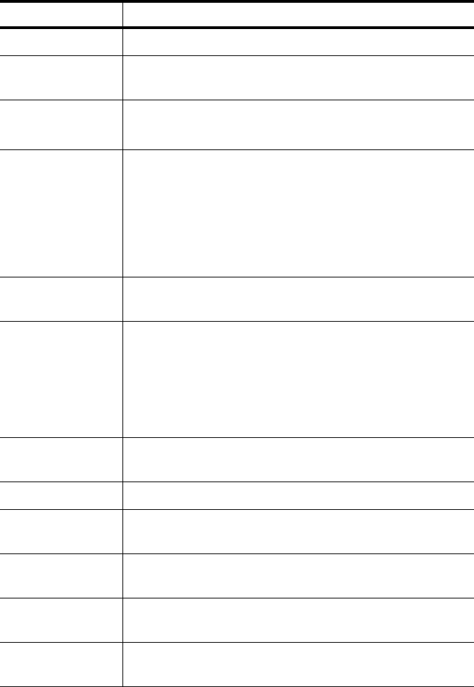
Table 1: Acronyms and their descriptions
Acronym Description
ADSL Asymmetrical Digital Subscriber Line
AP Access Point
ACS Auto Configuration Server
DHCP Dynamic Host Configuration Protocol

Contacting Global Service and Support
SkyZhone 1624, 1424, 1224 Hardware Installation Guide 9
Contacting Global Service and Support
Contact Global Service and Support (GSS) if you have any questions about
this or other Zhone products. Before contacting GSS, make sure you have the
following information:
•Zhone product you are using
•System configuration
•Software version running on the system
•Description of the issue
DSL Digital Subscriber Line
EFM Ethernet in the First Mile
MALC Multi-Access Line Concentrator
MIB Management Information Bases
NAT Network Address Translation
NMS Network Management System
RADIUS Remote Authentication Dial In User Service
SHDSL Symmetric High-bit-rate Digital Subscriber Line
SLMS Single Line Multi-Service
SNMP Simple Network Management Protocol
TFTP Trivial File Transfer Protocol
VoIP Voice over IP
VoWi-Fi Voice-over-Wifi
VPN Virtual Private Network
WEP Wired Equivalent Privacy
Wi-Fi Wireless Fidelity (IEEE 802.11 wireless networking)
WMM Wi-Fi Multimedia
WPA Wi-Fi Protected Access
ZMS Zhone Management System
Table 1: Acronyms and their descriptions
Acronym Description
About This Guide
10 SkyZhone 1624, 1424, 1224 Hardware Installation Guide
Technical support
If you require assistance with the installation or operation of your product, or
if you want to return a product for repair under warranty, contact GSS. The
contact information is as follows:
If you purchased the product from an authorized dealer, distributor, Value
Added Reseller (VAR), or third party, contact that supplier for technical
assistance and warranty support.
Service requirements
If the product malfunctions, all repairs must be performed by the
manufacturer or a Zhone-authorized agent. It is the responsibility of users
requiring service to report the need for service to GSS.
E-mail support@zhone.com
Telephone (North America) 877-ZHONE20 (877-946-6320)
Telephone (International) 510-777-7133
Internet www.zhone.com/support
SkyZhone 1624, 1424, 1224 Hardware Installation Guide 11
1
THE SKYZHONE ACCESS POINT
This chapter provides an overview of the SkyZhone Wi-Fi outdoor access
point. It includes these sections:
•Overview, page 11
•SkyZhone features, page 13
•SkyZhone ordering information, page 20
Overview
The SkyZhone access point is a line-powered carrier class outdoor Wi-Fi
access point with 22 Mbps symmetric DSL backhaul to every unit. The
SkyZhone supports a variety of applications including VoIP, internet access,
mobile video, and enterprise VPNs optimized for citywide Wi-Fi deployments
by telephone companies.
SkyZhone enables telephone companies to deploy a more reliable, lower
latency, higher speed and lower cost network than traditional mesh Wi-Fi
solutions.
The SkyZhone access point
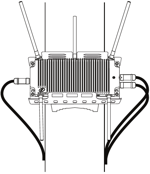
12 SkyZhone 1624, 1424, 1224 Hardware Installation Guide
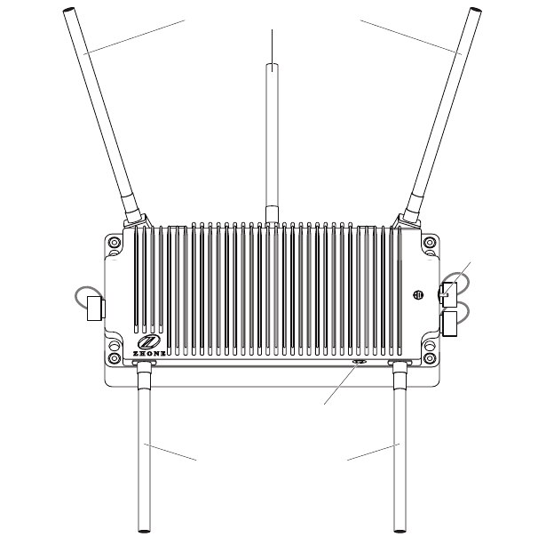
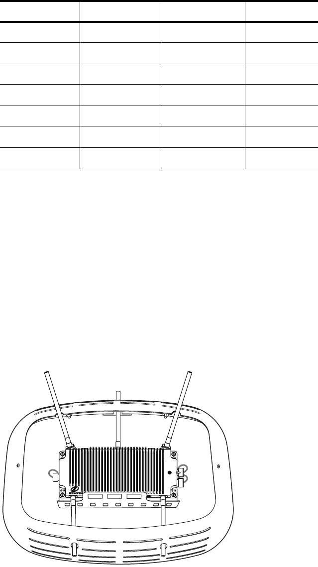
Figure 1: SkyZhone with 2.4GHz 802.11b/g/n and 4.9 GHz 802.11a antennas
SkyZhone models
The SkyZhone access point is available in the following models:
•SkyZhone-1624 Wi-Fi Access Point
Supports wireless radio transmission of 2.4 GHz 802.11b/g, and 4.9 GHz
802.11a, using two separate radios. Four SHDSL lines with EFM
Bonding are used for backhaul and line powering.
•SkyZhone-1424 Wi-Fi Access Point
Supports wireless radio transmission of 4.9 GHz 802.11a. Four SHDSL
lines with EFM Bonding are used for backhaul and line powering.
•SkyZhone-1224 Wi-Fi Access Point
Supports wireless radio transmission of 2.4 GHz 802.11b/g. Four SHDSL
lines with EFM Bonding are used for backhaul and line powering.
Coverage area
With the SkyZhone access point, there is no need to use Wi-Fi links for
communication between stations. This eliminates issues associated with
buildings, trees, or hilly terrain that can impact node-to-node communications
for mesh access points.
Console port
Ethernet port
Ground
SHDSL port
LED status light
4.9 GHz 802.11a antennas
2.4 GHz 802.11b/g/n antennas
SkyZhone features
SkyZhone 1624, 1424, 1224 Hardware Installation Guide 13
The SkyZhone access point uses 5dBi antennas that provide a 26 degree
beam-width per antenna. Additionally, the three 2.4 GHz antennas are
oriented to provide complete coverage both horizontally and vertically.
SkyZhone access point’s signals extend up and down, and all around to
minimize dead spots.
MIMO (Multiple-In, Multiple-Out) technology maximizes the receive signal
strength from typical low-power 802.11b/g client devices and enables
SkyZhone to maintain a reliable link at distances more than 50% greater than
non-MIMO solutions.
In Figure 1 on page 12, note that the 4.9 GHz 802.11a radio uses the bottom
two antennas and the 2.4 GHz 802.11b/g radio uses the top three antennas.
The 2.4 GHz radio operates in the unlicensed ISM band and can be used for a
variety of applications such as Internet Access, Voice over IP, Mobile Video,
or Enterprise VPN.
The 4.9 GHz radio operates in the licensed spectrum reserved for Public
Safety users including city government, police, fire and EMT.
SkyZhone features
The SkyZhone access points communicate with SkyZhone aggregators using
standards-based SHDSL-EFM uplinks to transport data traffic between access
points and the Central Office or remote cabinet.
After initial power up, the SkyZhone access point contacts the ACS Server,
downloads the latest software, downloads the configuration file, and registers
itself with the Network Management System (NMS) system.
The SkyZhone access points’ dual-radio architecture provides 2.4GHz access
for residential and commercial applications while simultaneously providing
4.9GHz access for public safety applications, using industry standard IEEE
802.11 client devices.
Remote configuration and troubleshooting is supported via SSH and HTTPS
to SkyZhone access points through a separate management VLAN. In
addition, a console port is provided for local access to the CLI.
SkyZhone also includes a Power-over-Ethernet (PoE) port which provides for
connectivity from the SkyZhone access point to a video camera or other
accessory.
Bonding
The SkyZhone access point supports Ethernet in the First Mile (EFM)
bonding on SHDSL lines. This bonding complies with the IEEE 802.3ah
standard. Additional SHDSL lines can be added as your bandwidth needs
increase. The SkyZhone access point automatically performs load balancing
over the SHDSL lines.
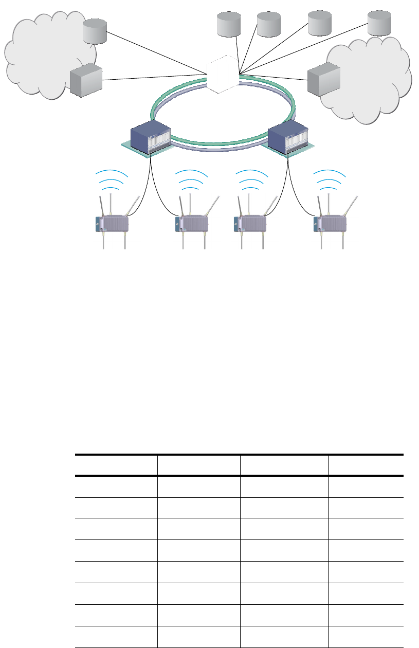
Figure 2 shows an example of a SkyZhone network configuration.
The SkyZhone access point
14 SkyZhone 1624, 1424, 1224 Hardware Installation Guide
Figure 2: SkyZhone network configuration
The SkyZhone supports 4 SHDSL lines bonded as a single EFM interface and
connected to a SHDSL card installed in a SkyZhone Aggregator. Each
SHDSL line card in the SkyZhone Aggregator provides 24 ports and each
SkyZhone access point uses up to 4 ports. The data rates for the SHDSL card
are shown in Table 2:
SHDSL Data Rates
The SkyZhone Access Points support the following SHDSL data rates.
SHDSL Data Rates
ACS Server DHCP Server RADIUS Server
SkyZhone Wi-Fi Access Layer
Edge Aggregation Layer
Router
Municipal Router
VPN Server
Public Access
Internet
Municipality’s
Network
Router
SkyZhone
Aggregator SkyZhone
Aggregator
ZMS Server
Table 2: SHDSL Data Rates
Distance (Feet) Line 1 (Kbps) Line 2 (Kbps) Line 4 (Kbps)
4000 5696 11392 22784
5000 5120 10240 20480
6000 3776 7552 15104
7000 2944 5888 11776
8000 2432 4864 9728
9000 2048 4096 8192
10000 1664 3328 6656
11000 1359 2718 5436
SkyZhone features
SkyZhone 1624, 1424, 1224 Hardware Installation Guide 15
Mounting options
The SkyZhone access point can be mounted on a pole, at any angle (between
vertical and horizontal), on a streetlight, loop span, or wall.
Wall-Mounting Enclosure
When wall-mounted the SkyZhone access point may be contained in an
enclosed and “hidden” plastic casing that is supported on an aluminum
mounting shelf. The following figure shows the SkyZhone access point with
the enclosure lid removed.
Figure 3: Wall-Mount Enclosure with cover removed
See Chapter 3, Installing the SkyZhone access point, on page 27 for using the
wall-mounted enclosure kit.
12000 1024 2048 4096
13000 768 1536 3072
14000 640 1280 2560
15000 512 1024 2048
16000 512 1024 2048
17000 384 768 1536
18000 320 640 1280
Table 2: SHDSL Data Rates
Distance (Feet) Line 1 (Kbps) Line 2 (Kbps) Line 4 (Kbps)
The SkyZhone access point
16 SkyZhone 1624, 1424, 1224 Hardware Installation Guide
Line power
The SkyZhone access point is powered by a SkyZhone aggregator over the
SHDSL link. There are four pairs of twisted wires on the uplink interface that
are capable of delivering power to the unit in addition to carrying the SHDSL
signals. Two powered pairs are required with the other two for longer loops.
The wiring diagram below illustrates the wiring connections for power and
data being transmitted over the same pair of wires..
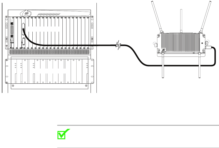
Figure 4: SHDSL backhaul with span powering
The SkyZhone access point supports power and data on the same wires.
Delivering power and data over the same wires
Note: For more information about the hardware required to deliver
power and data over the same wires, contact your Zhone sales
representative.
Cables
The SkyZhone Port Connectors
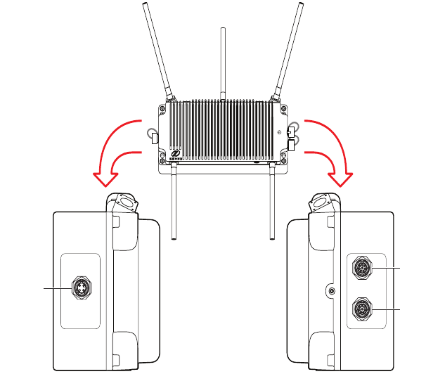
The port connectors are located on either side of the SkyZhone unit. Figure 5
shows the SkyZhone access point port locations.
SHDSL.bis line card
External Power Shelf
SkyZhone features
SkyZhone 1624, 1424, 1224 Hardware Installation Guide 17
Figure 5: SkyZhone port connectors
Console port
Ethernet port
SHDSL port
The SkyZhone access point
18 SkyZhone 1624, 1424, 1224 Hardware Installation Guide
SHDSL, Ethernet (PoE) and Console connectors
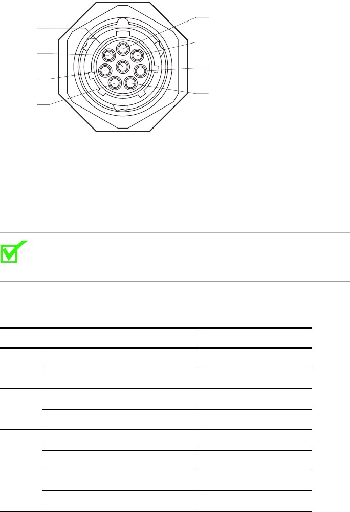
Figure 6 displays the pinouts for the SHDL PLUG connector.
Figure 6: SHDSL PLUG connector
Table 3 on page 18 lists the pinouts for the SHDSL cable. Each DSL line is
composed of a twisted-pair of wires. Two pairs are for power (RFT-V
voltages) and data and two pairs are for data only. To operate on longer loops
power is required on Tip/Ring 3 and 4. These wires can be used in any
combination, although positive voltage is typically carried on T/R1 and T/R3,
while negative voltage is on T/R2 and T/R4.
Note: The mechanical configuration (SOCKET vs. PLUG) of the
SHDSL and the Power-over-Ethernet connectors are unique to
prevent attaching a cable to the wrong connector.
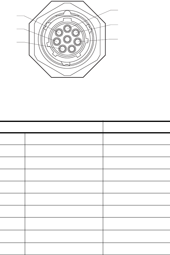
Ethernet (PoE)
Figure 7 displays the pinouts for a PoE SOCKET connector.
Table 3: SHDSL connector pinouts for line power and data over the same wire
pairs
Line Signal Color
1 Ring 1 (data and power) Blue
Tip 1 (data and power) White/Blue
2 Ring 2 (data and power) Orange
Tip 2 (data and power) White/Orange
3 Ring 3 (data and additional power) Green
Tip 3 (data and additional power) White/Green
4 Ring 4 (data and additional power) Brown
Tip 4 (data and additional power) White/Brown
Ring 4
Tip 4
Tip 3
Ring 3
Ring 1
Tip 1
Tip 2
Ring 2
SkyZhone features
SkyZhone 1624, 1424, 1224 Hardware Installation Guide 19
Figure 7: PoE SOCKET connector
Table 4 lists the pinouts for the Ethernet (PoE) cable. Unused PoE connectors
must have a dust cap installed to maintain an IP66 rating.
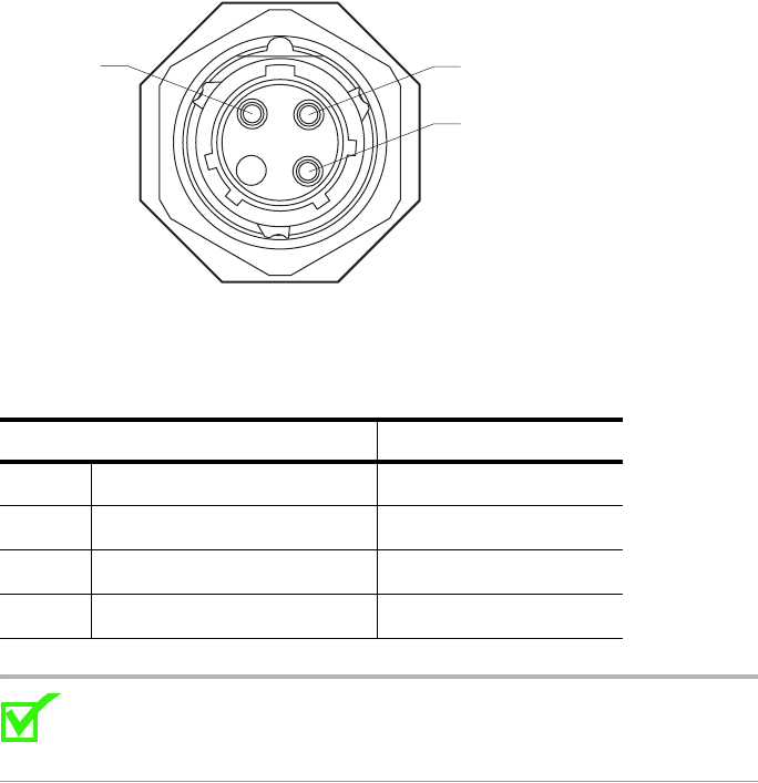
Console
Figure 8 displays the pinouts for a Console SOCKET connector. This
connector is for temporary use to configure the SkyZhone before mounting.
Any cabling to the console connector must be removed from the permanent
installation to avoid shock hazards. Dust caps must be installed to maintain an
IP66 rating.
Table 4: Power-over-Ethernet (PoE) connector pinouts for line power
Pin Signal Color
ATX_P Blue
B TX_N White/Blue
C RX_P Orange
D RX_N White/Orange
E No connection
F48V Green
G Return_48V White/Green
H No connection
I No connection
J No connection
TX_N
RX_P
RX_N
TX_P
RTN_48V
48V
The SkyZhone access point
20 SkyZhone 1624, 1424, 1224 Hardware Installation Guide
Figure 8: Console SOCKET connector
Table 5 lists the pinouts for the Console SOCKET cable.
Note: For more information about the hardware required to deliver
power and data over the same wires, contact your Zhone sales
representative.
Grounding
Proper grounding must be complete before you connect power to the unit. See
Grounding on page 37.
SkyZhone ordering information
To order SkyZhone Wi-Fi outdoor access points by model number contact
GSS, see Contacting Global Service and Support on page 9.
Table 5: Console SOCKET connector pinouts for line power
Pin Signal Color
1DCE_RXD Brown
2 No connection
3DCE_TXD White
GND GND Black
DCE RXD Ground
DCE TXD
SkyZhone 1624, 1424, 1224 Hardware Installation Guide 21
2
PREPARING FOR INSTALLATION
This chapter describes how to prepare your site for the installation of the
SkyZhone. It includes the following sections:
•Installation precautions, page 21
•Selecting the locations, page 23
•Specifications, page 23
Installation precautions
It is advisable to be aware of the following precautions:
WARNING! This unit is powered by high voltage over the
SHDSL lines. Electrical shock can occur by touching the
leads with the power on. Span power supply has current
limiters to prevent personal injury due to shock. Verify that
the SHDSL lines are deenergized before installing the
equipment. Always turn the power off by opening the relays
of the Aggregator before installing this equipment.
WARNING! Serious injury can occur if the antennas come in
contact with electric power lines. Carefully follow the
instructions in this manual. During and after installation, the
antennas must be a minimum of 24 inches from any power
lines. Use caution when installing this outdoor equipment.
WARNING! The National Electrical Code (NEC) and
Canadian Electrical Code (CEC) require the use of an agency
listed (UL/CSA) Building Entrance Protector for all power
and data communications cables entering a building. This is
to protect the building and occupants from damage caused by
transient voltage and current surges.
WARNING! A UL 497 (CSA C22.2 No. 226-92) approved
primary protection device must be used at the building
entrance. Also check with local wiring codes.
Preparing for installation
22 SkyZhone 1624, 1424, 1224 Hardware Installation Guide
WARNING! The unit is sealed at the factory and must not be
opened in the field. The unit shall be returned to the factory
for repairs.
•SkyZhone product requires professional installation.
•This equipment has been tested and found to comply with the limits for a
Class C digital device, pursuant to part 15, subpart C, of the FCC rules.
These limits are designed to provide reasonable protection against
harmful interference when the equipment is operated in a commercial
environment. This equipment generates, uses, and can radiate radio
frequency energy and, if not installed and used in accordance with the
user manual, may increase the potential for harmful interference to radio
communications.
•The SkyZhone-1424 equipment has been tested and found to comply with
the limits for a Class A digital device, pursuant to Part 15 of the FCC
Rules. These limits are designed to provide reasonable protection against
harmful interference when the equipment is operated in a commercial
environment. This equipment generates, uses, and can radiate radio
frequency energy and, if not installed and used in accordance with the
instruction manual, may cause harmful interference to radio
communications. Operation of this equipment in a residential area is
likely to cause harmful interference in which the user will be required to
correct the interference at his own expense.
WARNING! The authority to operate SkyZhone-1424
equipment is conditioned by the requirement that no
modifications will be made to the equipment unless the
changes or modifications are expressly approved by the
manufacturer.
•The PoE (Power over Ethernet) connector sources power to other devices.
Some devices may not be compatible with this feature. In that case, do not
connect the wires that supply the power. The power is 48 volts DC, at a
maximum of 5 watts.
•This unit can only be used with approved antennas that are shipped with
the unit. Antennae should be kept at least 10 inches away from contact
with the general public passing by the area.
•Proper grounding of the SkyZhone platform must be completed before
you connect power to the unit.
–The internal subassemblies signal/Logic ground is internally bonded
to the Safety Ground (chassis).
–SkyZhone provides both Primary and Secondary lightning and surge
protection to the SHDSL and PoE cable signals. The Console cable
signals are not protected and this cable, which is not intended for
outdoor use, should not be connected when the unit is installed.
Selecting the locations
SkyZhone 1624, 1424, 1224 Hardware Installation Guide 23
–The SHDSL cable that carries RFT-V power to the unit has no
connection to the Chassis Ground. This cable shield is only intended
to add durability and mechanical protection of the internal wires.
–Proper Safety Grounding is required to insure proper operation and
protection from lightning strikes and surges. A copper ground lug is
provided on the unit for this purpose. Connect a length of #10 AWG
solid, bare, copper wire to the grounding lug and firmly tighten the
grounding screw (see Grounding on page 37). Connect the other end
of the grounding wire to a grounded surface or another earth ground
such as a metal rod.
•No modifications or changes to this equipment are allowed, unless the
changes or modifications are expressly approved by the manufacturer. It
is recommended that shielded cables be used to reduce interference
whenever interference is suspected.
Selecting the locations
Each installation is unique due to the physical environment. Before installing
each SkyZhone access point, perform a site survey to determine the optimum
placement of units for maximum range, coverage, and network performance.
The SkyZhone radio is susceptible to interference that can reduce data rate
and range. For best performance, follow these guidelines:
•Install the unit in an area where trees, buildings, and large steel structures
do not obstruct radio signals to and from the antenna. Be sure to consider
the future tree growth and construction when considering a site. Direct
line-of-sight operation is always best. Antennae should be kept at least 8
inches away from contact with the general public passing by the area.
•Install the units away from other possible sources of 2.4 GHz WLAN
interference. These sources include cordless phones and microwave
ovens, as well as other WiFi access points.
•Install the units, when wall-mounted, onto an area that can accommodate
the plastic casing and lid of 24 inches high and at least 36 inches wide.
Specifications
The following table lists SkyZhone’s technical specifications:
Table 6: SkyZhone technical specifications
Description Specifications
PHYSICAL
Dimensions 14” W x 6”H x 6”D
Preparing for installation
24 SkyZhone 1624, 1424, 1224 Hardware Installation Guide
Weight 18 lbs
Operating
Temperature
-31F to 122F (-35C to 50C)
Power +/- (70-140) VDC input (RFT-V Signals), 45W Maximum
Span powered on two or four Tip/Ring pairs.
Line Power input
Capacitance
Tip - Ring < 2 uF
Tip - Gnd < 1000 pF
Ring - Gnd < 1000 pF
(Note: When combined with telco cable the Tip-Gnd and
Ring to Gnd cannot exceed 10 uF. This should be verified
with the Telco before installation)
Backhaul 22.8 Mbps symmetric backhaul using ITU G.991.2 (SHDSL)
on four Tip/Ring pairs.
Regulatory
Certifications
FCC Part 15, Subpart-C (15.247)
FCC Part 15, Class A
FCC Part 90
UL60950-1, UL60950-21
Industry Canada RSS210 CAN/CSA-22.2 No. 60950-1-03
Enclosure/
Humidity and Dust
IP66, NEMA4X, IEC 60529
MANAGEMENT
Management
Interfaces
WEB I/F, Command Line I/F, SNMPv2, TR-069
Management
Access
HTTPS, SSH, TR-069
Mgmt Access
Security
RADIUS password authentication
Wi-Fi Access
Security
IEEE 802.1X, WPA/WPA2, WEP
Table 6: SkyZhone technical specifications (Continued)
Description Specifications
Specifications
SkyZhone 1624, 1424, 1224 Hardware Installation Guide 25
Standards
Compliance
EN60950
IEEE 802.11b, g, n (draft) (2.4 GHz Wireless)
IEEE 802.11a (4.9 GHz Wireless)
IEEE 802.1D Bridging
K.20 Surge Immunity
IEEE 802.3ah (2Base-TL) Ethernet in the first mile
IEEE 802.1Q VLANS
IEEE 802.1p Priority
IEEE 802.3u 10/100 Base-TX (Power over Ethernet I/F)
ITU 991.2 Annex A and F
Frequency Band 2.412 - 2.462 GHz (2.4 GHz Wireless)
4.900 - 4.990 GHz (4.9 GHz Wireless)
Channel Width 20 MHz (2.4 GHz Wireless)
20 MHz (4.9 GHz Wireless)
Output Power
(EIRP)
1.15 W (2.4 GHz Wireless)
4.74 W (4.9 GHz Wireless)
Antenna Type 3 x 5 dBi Omni (2.4 GHz Wireless)
2 x 5.3 dBi Omni (4.9 GHz Wireless)
Modulation
Technique
PSK, DQPSK, DBPSK, OFDM (2.4 GHz Wireless)
OFDM (4.9 GHz Wireless)
Data Rates (Mbps) 2.4 GHz Wireless (Channels 1-11)
b: 11, 5.5, 2, 1
g: 54, 48, 36, 24, 18, 12, 9, 6
4.9 GHz Wireless (4.96 GHz and 4.98 GHz center freq.)
a: 54, 48, 36, 24, 18, 12, 9, 6
Operating
Distance
Up to 1300 DC Ohm loop loss (SHDSL I/F) ) - Model and
PoE power use dependent.
Up to 300 feet (Power over Ethernet I/F)
Up to 1800 feet 2.4 GHz 802.11 b/g and 4.9 GHz 802.11a
Connector Type 8 pin circular I/O PLUG (SHDSL I/F)
8 pin circular I/O SOCKET (Power over Ethernet I/F)
WAN I/F
Data Rate (per
pair)
Up to 5.7 Mbps Full Duplex
Number of pairs 4 (up to 22.8 Mbps total)
Table 6: SkyZhone technical specifications (Continued)
Description Specifications

Loop Bonding IEEE 802.3ah (EFM)
Power over
Ethernet I/F
Data Rate 10Mbps/100Mbps
Number of Ports 1
Output Power 48V DC, maximum 5W
Data Path
VLAN support IEEE 802.1Q
Traffic
Prioritization
IEEE 802.1p, 802.11e, IP TOS
Number of Priority
Queues
4
Traffic
Classification
Based on priority bits, protocol type, IP address
Rate Limiting Upstream and downstream rate limiting per classified flow
Table 6: SkyZhone technical specifications (Continued)
Description Specifications
SkyZhone 1624, 1424, 1224 Hardware Installation Guide 27
3
INSTALLING THE SKYZHONE ACCESS POINT
This chapter describes how to mount the SkyZhone access point on a pole or
on the side of a building. It includes the following topics:
•Equipment needed for installation, page 27
•Mounting the SkyZhone to a pole, page 29
•Mounting the SkyZhone to the side of a building, page 32
•Grounding, page 37
•Initial Configuration, page 38
Note that:
•The SkyZhone access point must always be mounted with the top of the
unit horizontal and level.
•It is best to mount the SkyZhone access point to a metal structure. The
metal mounting brackets are designed to make good contact with the pole,
thereby assuring good quality connection to the grounded structure.
•The SkyZhone access point ships in a container with the antennas. The
antennas are inside the protective foam, beneath the flap at the top. Do not
throw away the foam.
Equipment needed for installation
Pole-mounting kit
The SkyZhone access point’s pole-mounting kit (920-07821-01) contains the
following items:
•One universal pole bracket that can be oriented for use on small or large
diameter poles
•One SkyZhone support shelf with sun shield
•One nut to attach shelf to the center stud on the pole bracket
•Banding
•4 screws to securely fasten shelf to the pole bracket
Installing the SkyZhone access point
28 SkyZhone 1624, 1424, 1224 Hardware Installation Guide
•1 driver bit for the tamper-resistant screws
Wall-mounting enclosure kit
The SkyZhone access point wall-mounting enclosure kit (920-07811-01)
contains the following items:
•One wall bracket
•One paintable decorative cover
•4 (four) tamper-resistant mounting screws to mount the unit to the bracket
•6 (six) mounting screws for the decorative cover
•1 driver bit for the tamper-resistant screws
•Not included: 4 screws that will go through the metal bracket, plastic
cover and into your wall’s surface.
Wall-mount kit (without plastic cover)
The SkyZhone access point wall-mount kit (without plastic cover)
(SkyZhone-1224 Wi-Fi Access Point) contains the following items:
•One wall bracket
•4 (four) tamper-resistant screws
•1 driver bit for the tamper-resistant screws
Customer supplied equipment
For installation, you need the following items:
•Band tensioner (BAND-IT Tool C001) with cutter
Examples of tensioners are:
Pok-It II Tool (CJ020)
Ratchet Tool (C400
Bantam Tool (C075)
Bantam Strapping Tool (C085)
Heavy Duty BAND-IT Tool (C003)
Thriftool (J075)
Giant Tool (G402)
•7/16-inch nut driver
Mounting the SkyZhone to a pole
SkyZhone 1624, 1424, 1224 Hardware Installation Guide 29
•cordless screwdriver with a 2 1/2 " extension to be able to secure the
tamper-resistant screws, or a screwdriver that can receive a
tamper-resistant screw that is at least three inches long.
Mounting the SkyZhone to a pole
This section describes the steps to mount a pole for the SkyZhone access
point. First select a mounting location. You can attach the SkyZhone access
point to any pipe or pole.
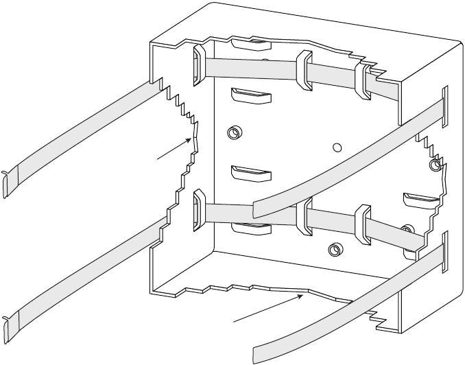
1Attach tension bands to the pole mounting plate by threading them
through the slots on the mounting plate. The slots are for either horizontal
or vertical mounting on large or small diameter poles. Choose the one
most appropriate for this installation.
Figure 9: Threading tension bands through mounting plate slots
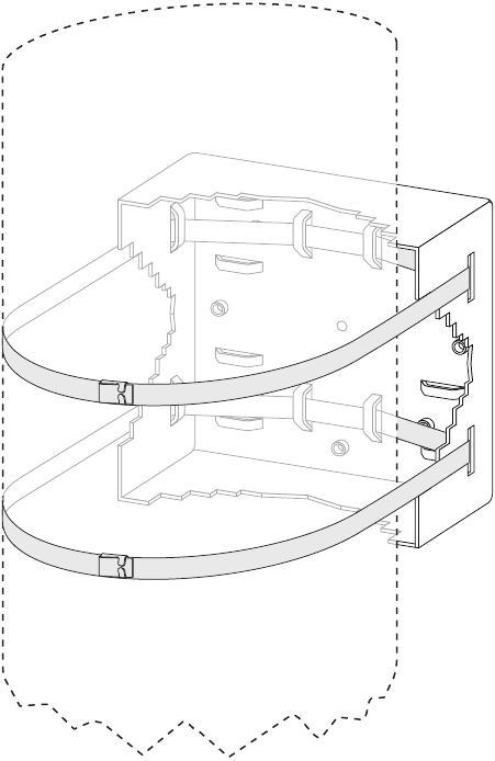
2Secure the tension bands around the pole, following the illustrations
provided with the BAND-IT Tool.
Small diameter
poles use this side
of the mounting
surface
Large diameter poles
use this side of the
mounting surface
Installing the SkyZhone access point
30 SkyZhone 1624, 1424, 1224 Hardware Installation Guide
Figure 10: Mounting plate “strapped” around a pole
3Tighten and if necessary, trim off any excess tension band.
4Secure the mounting bracket to the pole, see Figure 11 on page 31.
The SkyZhone shelf is attached to the poll-mounting bracket. The shelf
may need to be adjusted so that it is level.
Mounting the SkyZhone to a pole
SkyZhone 1624, 1424, 1224 Hardware Installation Guide 31
Figure 11: Bracket attached to the mounting plate attached to the pole
5Adjust the shelf until it is level by rotating the unit along the curved slot
tracks.
6Once the unit is level, securely tighten the center nut and four bolts that
hold the shelf to the pole mount bracket as shown in Figure 11.
7Attach the antennas to the unit.
Note the antennas are different sizes. The three longer antennas are
connected to the top of the unit. The two shorter antennas are mounted to
the bottom of the unit. The antennas are not interchangeable. It is critical
that the longer antennas are on the top, and the shorter ones on the bottom
of the unit.
8Slide the unit into the sun shield housing.
9Secure with 4 (four) tamper-resistant screws, provided in the mounting
kit, through the holes on the front of the unit.
10 Attach the SHDSL cable to the SHDSL connector.
11 Attach the Ethernet cable if it is being used.
12 Secure the cable(s) to the pole with cable ties to provide strain relief, if
needed.
Installing the SkyZhone access point
32 SkyZhone 1624, 1424, 1224 Hardware Installation Guide
Note: This previous procedure showed the SkyZhone station being
mounted to a vertical pole. The same instructions apply to the
installation on a horizontal pole or any other orientation as shown in
the figure below.
Figure 12: The bracket and sunshield mounted on a horizontal pole
Mounting the SkyZhone to the side of a building
The wall mount enclosure kit is used when the SkyZhone is mounted to a
building. The cover is used to hide the unit for aesthetic purposes. This cover
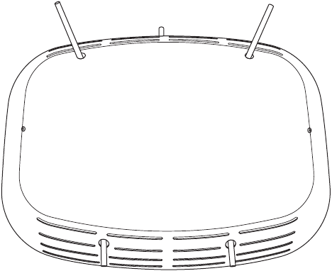
can be painted, which allows the unit to blend in with the building. Figure 13
displays a fully-assembled SkyZhone with its cover.
Mounting the SkyZhone to the side of a building
SkyZhone 1624, 1424, 1224 Hardware Installation Guide 33
Figure 13: SkyZhone with a cover
The SkyZhone wall mount enclosure kit (920-07811-01) includes the
following items:
•lid
•front cover
•bracket and base
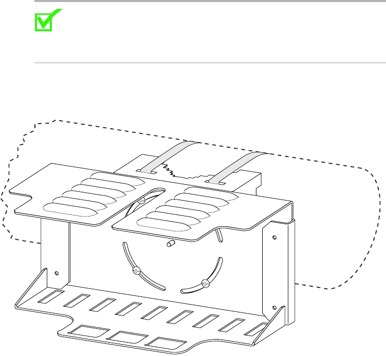
These items are also displayed in Figure 14:
Installing the SkyZhone access point
34 SkyZhone 1624, 1424, 1224 Hardware Installation Guide
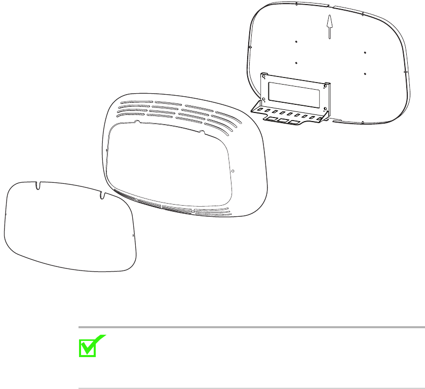
Figure 14: Contents of wall mount enclosure kit (from left: the lid, the front
cover, the bracket and the base)
To mount the optional cover
Note: The mounting of the SkyZhone unit should be as high as
possible to ensure maximum coverage. A flat surface measuring 24
inches high and 36 inches wide will be needed to mount the unit
securely.
1Find a flat surface that is at least 24 inches tall and 36 inches wide.
2Drill the holes in the wall to align with the corresponding holes in the
mounting bracket. See Figure 15.
3Obtain the proper screws (not included) to anchor the wall mount
assembly to the type of surface it is being mounted to.
4Place the mounting bracket on the rear panel of the cover, lining up the
mounting holes.
5Fasten the mounting bracket in the desired location with the appropriate
type of screw. Use the outside holes displayed in Figure 16. These should
line up with the holes in the cover.
Mounting the SkyZhone to the side of a building
SkyZhone 1624, 1424, 1224 Hardware Installation Guide 35
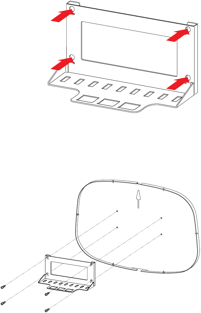
Figure 15: Mounting Bracket with screw locations
6Attach the mounting bracket and the base to the wall (Figure 16). (The
base has an UP arrow cut into the plastic casing to ensure in proper
orientation.) Use a 1/4 inch drill masonry bit to install a 1 inch plastic
insert to secure the cover and the aluminum frame to the concrete wall
with the appropriate screws.
Figure 16: Bracket and Base
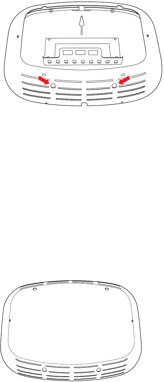
7Attach the protective cover to the base and then attach the base to the
(concrete) wall. Note that the cover should be attached so that the
top contains the two cutouts for the angled antennas.
Installing the SkyZhone access point
36 SkyZhone 1624, 1424, 1224 Hardware Installation Guide
Figure 17: Base, Bracket, and Front Cover displaying two holes for antennas
8Attach the antennas to the SkyZhone access point.
Note that the antennas are different sizes. The three longer antennas are
connected to the top of the unit. The two shorter antennas are mounted to
the bottom of the unit. The antennas are not interchangeable. It is critical
that the longer antennas are on the top, and the shorter ones on the bottom
of the unit.
9Slide the SkyZhone station onto the wall mounting bracket.
10 Secure the SkyZhone to the wall mounting bracket with the 4 (four)
tamper-resistant screws, provided in the installation kit, through the holes
on the front of the unit.
11 Attach the SHDSL cable. Also connect the optional console cable and
Ethernet cables, if they are being used. In some installations, it might be
easier to install the cables before mounting the unit to the bracket.
12 Attach the lid of the protective cover and secure it with the screws
provided in the installation kit. The final assembly appears in Figure 18,
and the final installation appears in Figure 19.
Figure 18: Wall Mount Kit - Final Assembly
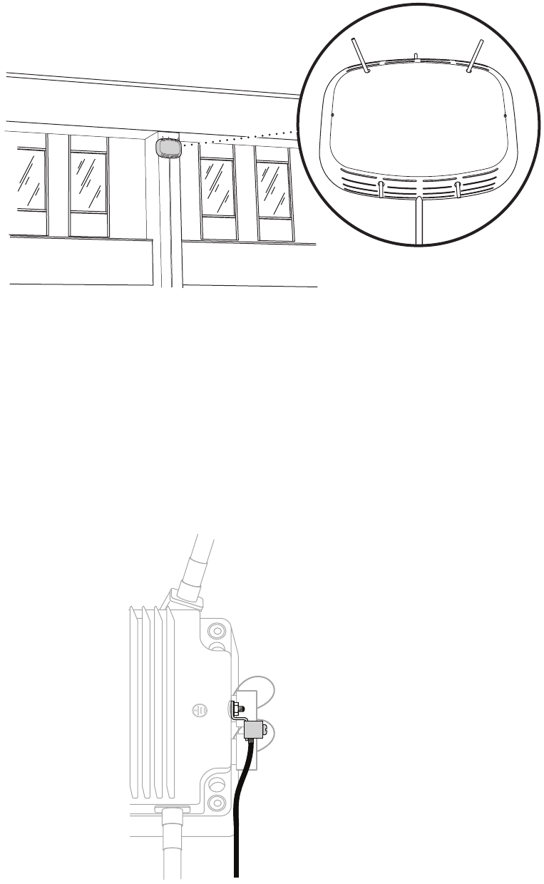
Grounding
SkyZhone 1624, 1424, 1224 Hardware Installation Guide 37
Figure 19: Example of a wall-mounted SkyZhone
Grounding
To ensure proper grounding:
•Connect a length of #10 AWG solid bare copper wire to the wire
grounding lug of the unit and tighten the grounding nut. See Figure 20.
•Connect the other end of the grounding wire strap that is attached to a
grounded surface or another earth ground such as a metal rod.
Figure 20: Grounding lug
Installing the SkyZhone access point
38 SkyZhone 1624, 1424, 1224 Hardware Installation Guide
Initial Configuration
Using the factory defaults
The factory defaults for the SkyZhone Access Point includes two VLANS.
•VLAN 1 is the default data VLAN.
Ports eth0 (SHDSL), eth1 (PoE), and wlan1 are all members of this
VLAN.
•VLAN 7 is the default management VLAN.
Ports eth0 (SHDSL) and eth1 (PoE) are members of this VLAN.
Before using the SkyZhone Access point, use the CLI commands on the
console interface to assign an IP address to the SkyZhone. For your network,
determine the appropriate IP addresses as well as subnet mask, default
gateway and broadcast address settings. The SkyZhone Access Point can now
be configured for management.
In the following example, the values for the settings for the network are:
•IP address: 10.108.14.218
•Subnet mask: 255.255.255.0
•Broadcast Address: 10.108.14.255
•Default gateway: 10.108.14.254
Use the following three commands to configure VLAN management.
•config if interface brvlan7 ip 10.108.14.218 mask 255.255.255.0
broadcast 10.108.14.255
•config if route-add destination default gateway 10.108.14.254
•config admin-tools save running-config
After entering these commands, the system can be managed using SSH or
HTTPS over the SHDSL interface or the PoE interface.
Refer to the SkyZhone CLI Reference Guide for a list of supported commands
to configure advanced SkyZhone features.
Changing the factory defaults
If you are not using the factory default VLANs, you need to delete the default
VLANs and configure the VLANs that are appropriate for your network. In
the example below, VLAN 2 is used for management instead of the default
VLAN 7. Also, VLAN 122 is the data VLAN instead of VLAN 1.
Initial Configuration
SkyZhone 1624, 1424, 1224 Hardware Installation Guide 39
1Delete the default VLANS. The following commands remove the default
VLANs:
config vlan vlanconfig removeport interface eth1
vlanid 1
config vlan vlanconfig removeport interface eth0
vlanid 1
config vlan vlanconfig removeport interface wlan1
vlanid 1
config vlan vlanconfig removevlan vlanid 1
config vlan vlanconfig removeport interface eth1
vlanid 7
config vlan vlanconfig removeport interface eth0
vlanid 7
config vlan vlanconfig removevlan vlanid 7
2Define the new management VLAN. In this example, VLAN 2 is the
management VLAN.
config vlan vlanconfig addvlan vlan_name management
vlanid 2
config vlan vlanconfig addport interface eth0 vlanid 2
tagged
config vlan vlanconfig addport interface eth1 vlanid 2
untagged
config vlan portdefaults default-pvid vlanport eth1
pvid 2
3Configure the management address. In this example, the device address is
10.108.14.218.
config if interface brvlan2 ip 10.108.14.218 mask
255.255.255.0 broadcast 10.108.14.255
config if route-add destination default gw-addr
10.108.14.254
4Define the data VLAN. In this example, the data VLAN is VLAN 122.
config vlan vlanconfig addvlan vlan_name data vlanid 122
config vlan vlanconfig addport interface wlan0 vlanid
122 tagged
config vlan vlanconfig addport interface eth2 vlanid
122 tagged
config vlan vlanconfig addport interface eth3 vlanid
122 tagged
config admin-tools save running-config
Installing the SkyZhone access point
40 SkyZhone 1624, 1424, 1224 Hardware Installation Guide
Using the Ethernet interface
The Ethernet port can be used to configure the SkyZhone using the factory
default. The Ethernet port on the SkyZhone has a default address of
192.168.1.1. If a static IP address is set on your PC that is on the same subnet
(for example, 192.168.1.100), then use HTTPS to configure the remaining
parameters. Note that the SkyZhone uses HTTPS and not HTTP. The default
login is admin and the default password is zhone.
Note that if the IP address of the management VLAN is changed, you lose
your connection to the SkyZhone unit. A new static IP address must be
configured on your PC that is compatible with the new IP address that you
configured in the SkyZhone unit.
Also, if any changes have been made to the VLAN definitions, the
corresponding changes will have to be made in the DSLAM that the
SkyZhone is connected to.
SkyZhone 1624, 1424, 1224 Hardware Installation Guide 41
4
DIAGNOSTICS
This chapter describes the SkyZhone access point’s LED light.
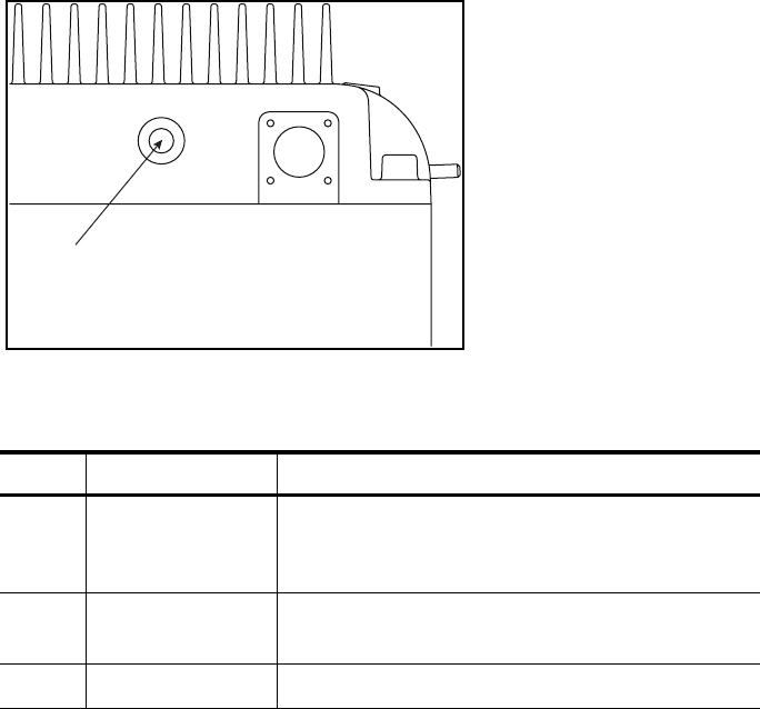
Status and LED
The SkyZhone contains one red LED located on the bottom right of the unit.
(Figure 21). The LED provides a quick verification as to whether it is
operating correctly or if it needs to be replaced.
Figure 21: LED Location
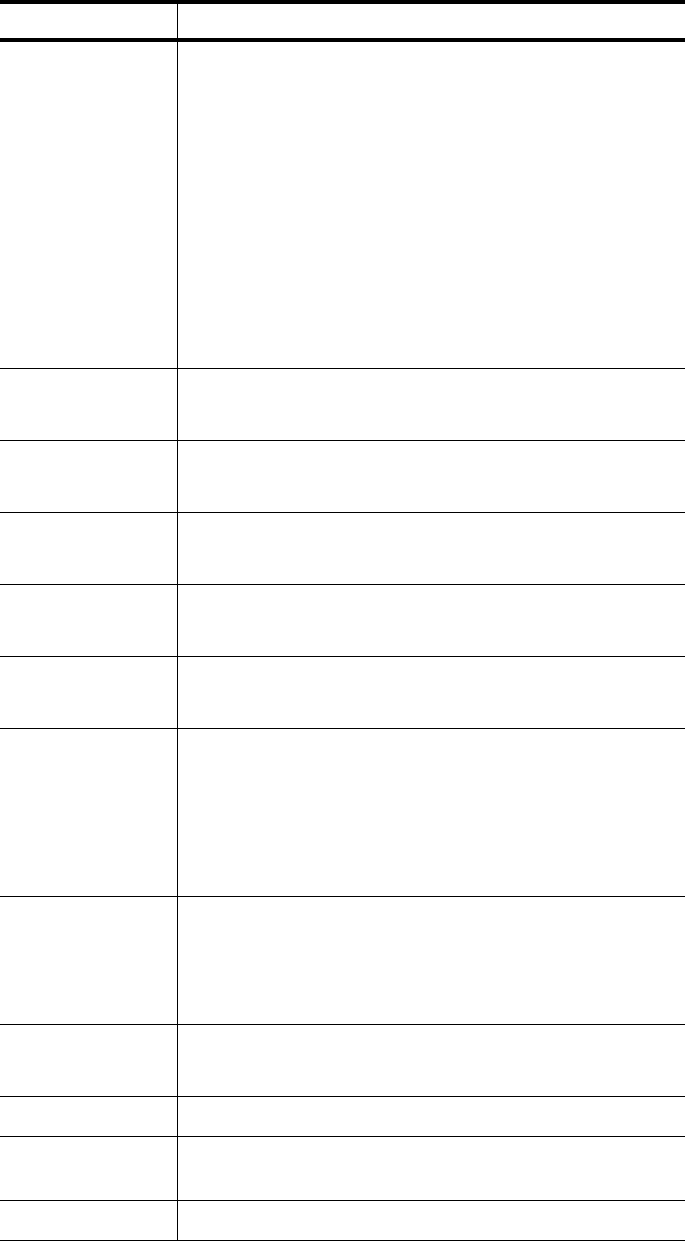
The following table describes the possible states of the LED light.
Color Operation Description
Red On solid Power is on and the software is not in an
operational state. If the LED stays in this state for
more than one minute, the unit should be replaced.
Red One blink every 3
seconds
Power is on and the unit is operational.
Off Off There is no power.
LED

EtherXtend User’s Guide 43
SAFETY, REGULATIONS, AND CERTIFICATIONS
This chapter describes how to prepare your site for the installation of the
SkyZhone platform. It includes the following topics:
•Safety on page 43
•Grounding and isolation on page 46
•Installation safety precautions on page 46
•Contacting Global Service and Support, page 51
Safety
WARNING!
The SkyZhone product is a line power device conforming to UL
60950-1 and UL 60950-21 standards. The DC voltages (RFT-V
signals) are provided to SkyZhone through the SHDSL connector.
These voltages must be provided by a UL 60950-1 and UL
60950-21 certified power source, typically located at the Central
Office. One such certified power source is the Argus Technologies
CSM35 Modular Converter System (#012-550-B2). Uncertified
power sources can result in injury or death.
Proper Safety Grounding is required to insure proper operation
and protection from lightning strikes and surges. A copper
ground lug is provided on the unit for this purpose. Connect a
length of #10 AWG solid, bare, copper wire to the grounding lug
and firmly tighten the grounding screw (see Figure 20). Connect
the other end of the grounding wire to a grounded surface or
another earth ground such as a metal rod. This ground must be
install before applying power to the unit.
SkyZhone provides both Primary and Secondary lightning and
surge protection to the SHDSL and PoE cable signals. The
Console cable signals are not protected and this cable, which is
not intended for outdoor use, should not be connected when the
unit is installed.
Safety, Regulations, and Certifications
44 SkyZhone 1624, 1424, 1224 Hardware Installation Guide
This unit is powered by high voltage over the SHDSL lines.
Electrical shock and personal injury can occur by touching the
leads with the power on. Verify that the SHDSL lines are
deenergized before installing or removing the equipment. Always
turn the power off at the DSLAM before installing or removing
this equipment.
The National Electrical Code (NEC) and Canadian Electrical
Code (CEC) require the use of an agency listed (UL/CSA)
Building Entrance Protector for all power and data
communications cables entering a building. This is to protect the
building and occupants from damage caused by transient voltage
and current surges.
A UL 497 (CSA C22.2 No. 226-92) approved primary protection
device must be used at the building entrance if the Ethernet port
is used to provide in-building access to the SkyZhone network.
Also check with local wiring codes.
Caution:
•The unit is sealed at the factory and must not be opened in the field.
The unit shall be returned to the factory for repairs.
•Serious injury can occur if the antennas come in contact with
electric power lines. Carefully follow the instructions in this
manual. During and after installation, the antennas must be a
minimum of 24 inches from any power lines. Use caution when
installing this outdoor equipment.
•FCC RF Exposure Requirements (per OET-65) requires the
SkyZhone platform to be mounted such that the general public does
not come within 10 inches of the antennae.
•The PoE (Power over Ethernet) connector sources power to other
devices. Some devices may not be compatible with this feature. In
that case, do not connect the wires that supply the power. The
power is 48 volts DC, at a maximum of 5 watts.
Note:
•This equipment has been tested and found to comply with the limits
for a Class C digital device, pursuant to part 15, subpart C, of the
FCC rules. These limits are designed to provide reasonable
protection against harmful interference when the equipment is
operated in a commercial environment. This equipment generates,
uses, and can radiate radio frequency energy and, if not installed
and used in accordance with the user manual, may increase the
potential for harmful interference to radio communications.
Safety
SkyZhone 1624, 1424, 1224 Hardware Installation Guide 45
•The SkyZhone-1424 equipment has been tested and found to
comply with the limits for a Class A digital device, pursuant to Part
15 of the FCC Rules. These limits are designed to provide
reasonable protection against harmful interference when the
equipment is operated in a commercial environment. This
equipment generates, uses, and can radiate radio frequency energy
and, if not installed and used in accordance with the instruction
manual, may cause harmful interference to radio communications.
Operation of this equipment in a residential area is likely to cause
harmful interference in which the user will be required to correct
the interference at his own expense
WARNING!
The authority to operate the SkyZhone-1424 equipment is
conditioned by the requirement that no modifications will be
made to the equipment unless the changes or modifications are
expressly approved by the manufacturer.
•Changes or modifications not expressly approved by Zhone
Technologies, Inc. could void the user's authority to operate the
equipment.
•The supplied cables and antennae must be used to ensure
compliance with Part 15, FCC Rules.
•This device may only be used with approved antennae that are
shipped with the unit and installed per installation instructions. The
use of any other antennas will invalidate the unit's FCC Part 15
certification.
•The 2.4 GHz band has been designed to operate with the antennae
listed below, and having a maximum gain of 5 dBi. Antennae not
included in this list (Comet Part Number CFA-245W-SR) or having
a gain greater than 5 dBi are strictly prohibited for use with this
device. The required antenna impedance is 50 ohms.
•The 4.9 GHz band has been designed to operate with the antennae
listed below, and having a maximum gain of 5.3 dBi. Antennae not
included in this list (Comet Part Number SF-D49NW-SR) or
having a gain greater than 5.3 dBi are strictly prohibited for use
with this device. The required antenna impedance is 50 ohms.
•To reduce potential radio interference to other users, the antenna
type and its gain should be so chosen that the equivalent
isotropically radiated power (e.i.r.p.) is not more than that
permitted for successful communication. Operating the device with
the supplied antennas will ensure that this requirement is met.

Safety, Regulations, and Certifications
46 SkyZhone 1624, 1424, 1224 Hardware Installation Guide
•Operation is subject to the following two conditions: (1) this device
may not cause interference, and (2) this device must accept any
interference, including interference that may cause undesired
operation of the device.
Grounding and isolation
Proper grounding of the SkyZhone platform must be completed before you
connect power to the unit.
•The internal subassemblies signal/Logic ground is internally bonded to
the Safety Ground (chassis).
•SkyZhone provides both Primary and Secondary lightning and surge
protection to the SHDSL and PoE cable signals. The Console cable
signals are not protected and this cable, which is not intended for outdoor
use, should not be connected when the unit is installed.
•The SHDSL cable that carries RFT-V power to the unit has no connection
to the Chassis Ground. This cable shield is only intended to add durability
and mechanical protection of the internal wires.
•Proper Safety Grounding is required to insure proper operation and
protection from lightning strikes and surges. A copper ground lug is
provided on the unit for this purpose. Connect a length of #10 AWG solid,
bare, copper wire to the grounding lug and firmly tighten the grounding
screw (see Figure 20). Connect the other end of the grounding wire to a
grounded surface or another earth ground such as a metal rod.
Installation safety precautions
Maximum ambient operating temperature should not exceed 500C (1220F).
Minimum ambient operating temperature should not exceed -350C (-310F).
Observe the maximum recommended operating temperature as indicated here.
Do not block system air vents; this will deprive the system of the airflow
required for proper cooling. Sufficient clearance must exist on all sides of the
rack to permit equipment access. Connect the system to the power supply
circuit as described in this document. Do not overload the system or power
supply circuit. Ensure that proper system grounding is performed and
maintained.

Installation safety precautions
SkyZhone 1624, 1424, 1224 Hardware Installation Guide 47
Important Safety Instructions
Read and follow all warning notices and instructions
marked on the product or included in the manual.
1The SkyZhone product is a line power device conforming to UL 60950-1
and UL 60950-21. The DC voltages (RFT-V signals) provided to
SkyZhone through the SHDSL connector must be provide by a UL
60950-1 and UL 60950-21 certified power source, typically located at the
Central Office. One such certified power source is the Argus
Technologies CSM35 Modular Converter System (#012-550-B2).
Uncertified power source should not be used. The installer must verify
this
2The Telco must be contacted to assure the cables providing the SHDSL
data and power to the unit are capable of carrying the RFT-V voltages
required.
3Do not attempt to service this product yourself, as opening or removing
covers may expose you to hazardous voltage or to other risks. Refer all
servicing to qualified service personnel.
5When installed, the product must comply with the applicable Safety
Standards and regulatory requirements of the country in which it is
installed. If necessary, consult with the appropriate regulatory agencies
and inspection authorities to ensure compliance.
4A rare phenomenon can create a voltage potential between the earth
grounds of two or more buildings. If products installed in separate
buildings are interconnected, the voltage potential may cause a hazardous
condition. Consult a qualified electrical consultant to determine whether
or not this phenomenon exists and, if necessary, implement corrective
action prior to interconnecting the products.
5In addition, since the equipment is to be used with telecommunications
circuits, take the following precautions:
— Never install telephone wiring during a lightning storm.
— Never install telephone jacks in wet locations unless the jack is
specifically designed for wet locations.
— Never touch uninsulated telephone wires or terminals unless the
telephone line has been disconnected at the network interface.
— Use caution when installing or modifying telephone lines.
— Avoid using a telephone (other than a cordless type) during an
electrical storm. There may be a remote risk of electric shock from
lightning.
—Do not use the telephone to report a gas leak in the vicinity of the
leak.
EMI Notices
The following are EMI notices.

Safety, Regulations, and Certifications
48 SkyZhone 1624, 1424, 1224 Hardware Installation Guide
United States - EMI Notice
•Changes or modifications not expressly approved by Zhone Technologies,
Inc. could void the user's authority to operate the equipment.
•The supplied cables and antennae must be used to ensure compliance with
Part 15 and Part 90, FCC Rules.
•This device may only be used with approved antennae that are shipped
with the unit and installed per installation instructions. The use of any
other antennas will invalidate the unit's FCC Part 15 certification.
•The 2.4 GHz band has been designed to operate with the antennae listed
below, and having a maximum gain of 5 dBi. Antennae not included in
this list (Comet Part Number CFA-245W-SR) or having a gain greater
than 5 dBi are strictly prohibited for use with this device. The required
antenna impedance is 50 ohms.
•The 4.9 GHz band has been designed to operate with the antennae listed
below, and having a maximum gain of 5.3 dBi. Antennae not included in
this list (Comet Part Number SF-D49NW-SR) or having a gain greater
than 5.3 dBi are strictly prohibited for use with this device. The required
antenna impedance is 50 ohms.
•To reduce potential radio interference to other users, the antenna type and
its gain should be so chosen that the equivalent isotropically radiated
power (e.i.r.p.) is not more than that permitted for successful
communication. Operating the device with the supplied antennas will
ensure that this requirement is met.
•Operation is subject to the following two conditions: (1) this device may
not cause interference, and (2) this device must accept any interference,
including interference that may cause undesired operation of the device.
Canada - EMI Notice
This Class A and C digital apparatus complies with Industry Canada RSS-210.

Installation safety precautions
SkyZhone 1624, 1424, 1224 Hardware Installation Guide 49
Supplier’s Declaration of Conformity
Place of Issue: Zhone Technologies
8545 126th Avenue North
Largo, FL 33773-1502
USA
Date of Issue: October 30, 2007
Zhone Technologies, located at the above address, hereby certifies that the
SKYZHONE-1224/1424/1624 bearing the FCC identification numbers
PJZSZ1224, PJZSZ1424, PJZSZ1624 complies with the Federal
Communications Commission's ("FCC") Rules and Regulations pursuant to
part 15, subpart C (14.247), part 15 Class A and part 90, as appropriate.
Additionally, the Industry Canada identification numbers 3619ASZ1224,
3619ASZ1424, 3619ASZ1624 insures that the SKYZHONE-1224/1424/1624
also meet the requirements of RSS-210. The unit has network certification
associated with ITU-T G.991.2.
Keith Nauman
Vice President

Safety, Regulations, and Certifications
50 SkyZhone 1624, 1424, 1224 Hardware Installation Guide
Notice to Users of the Canadian Telephone Network
NOTICE: This equipment has been certified to ITU-T G991.2
CE Marking
When the product is marked with the CE mark on the equipment label, a
supporting Declaration of Conformity may be downloaded from the Zhone
World Wide Web site at www.zhone.com.
Contacting Global Service and Support
SkyZhone 1624, 1424, 1224 Hardware Installation Guide 51
Contacting Global Service and Support
Contact Global Service and Support (GSS) if you have any questions about
this or other Zhone products. Before contacting GSS, make sure you have the
following information:
•Software version running on the system
•System configuration
•Zhone product you are using
•Description of the issue
Technical Support
If you require assistance with the installation or operation of your product, or
if you want to return a product for repair under warranty, contact GSS. The
contact information is as follows
If you purchased the product from an authorized dealer, distributor, Value
Added Reseller (VAR), or third party, contact that supplier for technical
assistance and warranty support.
Service Requirements
If the product malfunctions, all repairs must be performed by the
manufacturer or a Zhone-authorized agent. It is the responsibility of users
requiring service to report the need for service to GSS.
Table 7:
E-mail support@zhone.com
Telephone (North America) 877-ZHONE20
Telephone (International) 510-777-7133
Internet www.zhone.com/support

Safety, Regulations, and Certifications
52 SkyZhone 1624, 1424, 1224 Hardware Installation Guide
SkyZhone 1624, 1424, 1224 Hardware Installation Guide 53
INDEX
Numerics
2.4 GHz radio 13
4.9 GHz radio 13
A
acronyms, described 8
antenna 13
2.4 GHz 13
4.9 GHz 13
B
bonding 13
SHDSL lines 14
C
connector 18
Console SOCKET connector 19
Power-over-Ethernet (PoE) 18, 22
SHDSL 18
Console 19
Console SOCKET connector
connector 19
G
grounding requirements 37
I
installation
safety precautions 21
L
LED 41
line power requirements 16
M
mounting
pole 15
pole-mounting kit, contents 27
wall 15
wall-mounting enclosure kit, contents 28
N
network configuration 13
P
pinouts
Console SOCKETconnector 19
Power-over-Ethernet (PoE) connector 18
SHDSL connector 18
PoE 18
pole-mounting 15
kit, contents 27
Power-over-Ethernet (PoE)
connector 18, 19, 22
connector, pinouts 19
R
requirements
grounding 37
line power 16
S
safety precautions 21
SHDSL
backhaul 16
connector 18
connector, pinouts 18
lines 14
SkyZhone
access point, illustrated 11
antenna 13
bonding 13
LED 41
Index
54 SkyZhone 1624, 1424, 1224 Hardware Installation Guide
location sites 23
models 12
network configuration 13
W
wall-mounting 15
enclosure 15
enclosure kit, contents 28