DAVOLINK DV-201DM VoIP Gateway User Manual FCC CERTIFICATION B
DAVOLINK Inc. VoIP Gateway FCC CERTIFICATION B
UserManual.wiki
>
DAVOLINK
>
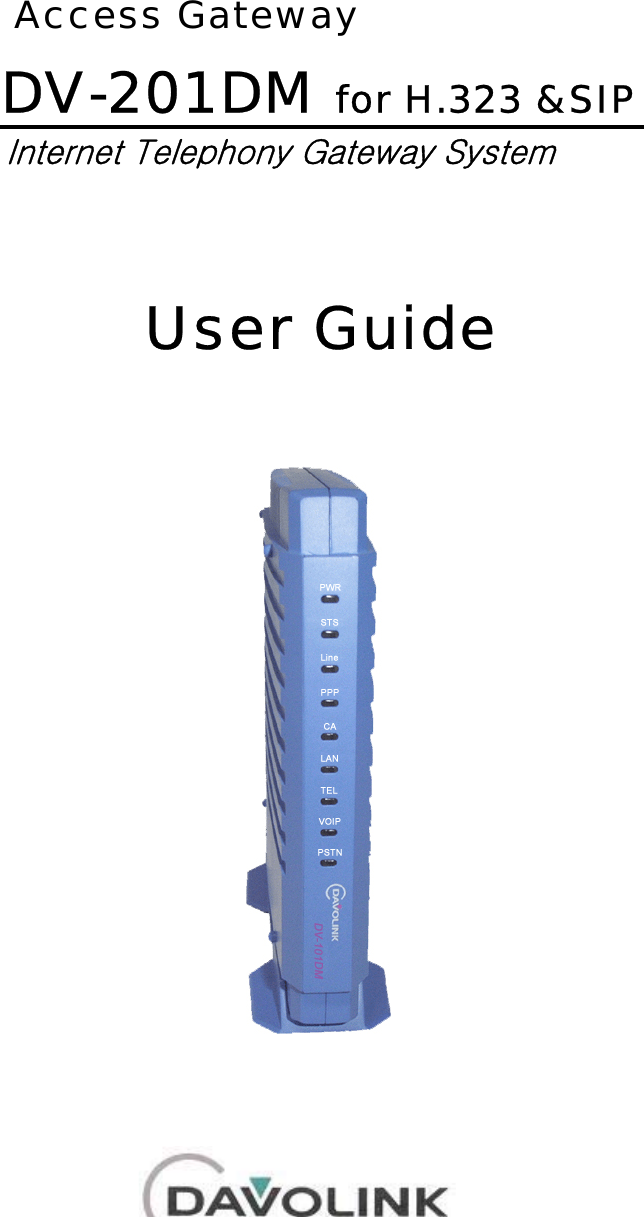
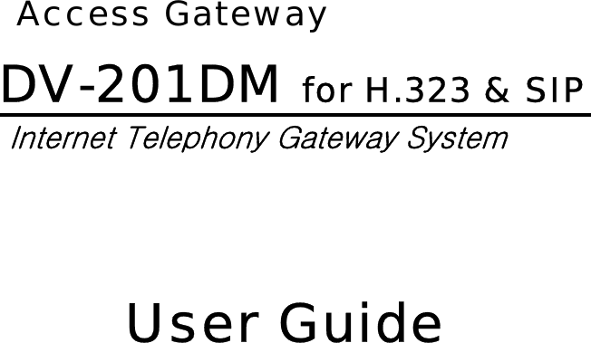
DV 201DM User Manual
User Manual
Navigation menu
Upload a User Manual
Namespaces
Wiki Guide
HTML
PDF
Info
Views
User Manual
Discussion / Help
Navigation


![DV-201DM for H.323 & SIP 6. Click “OK” button in internet protocol attribute window and then close all windows opened. 7. Open “COMMAND PROMPT” window and Execute “ipconfig” command to make sure that your PC is assigned IP address, subnet mask and default gateway value. (Verify: IP address range is between 192.168.1.10 ~ 192.168.1.29 ) Remember the IP Address value should be in 192.168.1.1~ 192.168.1.253, subnet mask should be 255.255.255.0, and Default Gateway should be 192.168.1.254. [c:\]ipconfig Windows IP Configuration Ethernet adapter local area connection: Connection-specific DNS Suffix . : IP Address. . . . . . . . . . . . : 192.168.1.10 Subnet Mask . . . . . . . . . . . : 255.255.255.0 Default Gateway . . . . . . . . . : 192.168.1.254 2 - 14](https://usermanual.wiki/DAVOLINK/DV-201DM/User-Guide-409989-Page-30.png)
![DV-201DM for H.323 & SIP 3. From windows, Goto “run”. Type in “command”. From “Command Prompt” screen, type “ping 192.168.1.254” and press “Enter”. If the following message is displayed, your computer is properly connected with DV-201DM. [c:\]ping 192.168.1.254 Pinging 192.168.1.254 with 32 bytes of data: Reply from 192.168.1.254: bytes=32 time=3ms TTL=255 Reply from 192.168.1.254: bytes=32 time=3ms TTL=255 Reply from 192.168.1.254: bytes=32 time=2ms TTL=255 Reply from 192.168.1.254: bytes=32 time=1ms TTL=255 Ping statistics for 192.168.1.254: Packets: Sent = 4, Received = 4, Lost = 0 (0% loss), Approximate round trip times in milli-seconds: Minimum = 1ms, Maximum = 3ms, Average = 2ms [c:\] 2 - 16](https://usermanual.wiki/DAVOLINK/DV-201DM/User-Guide-409989-Page-32.png)
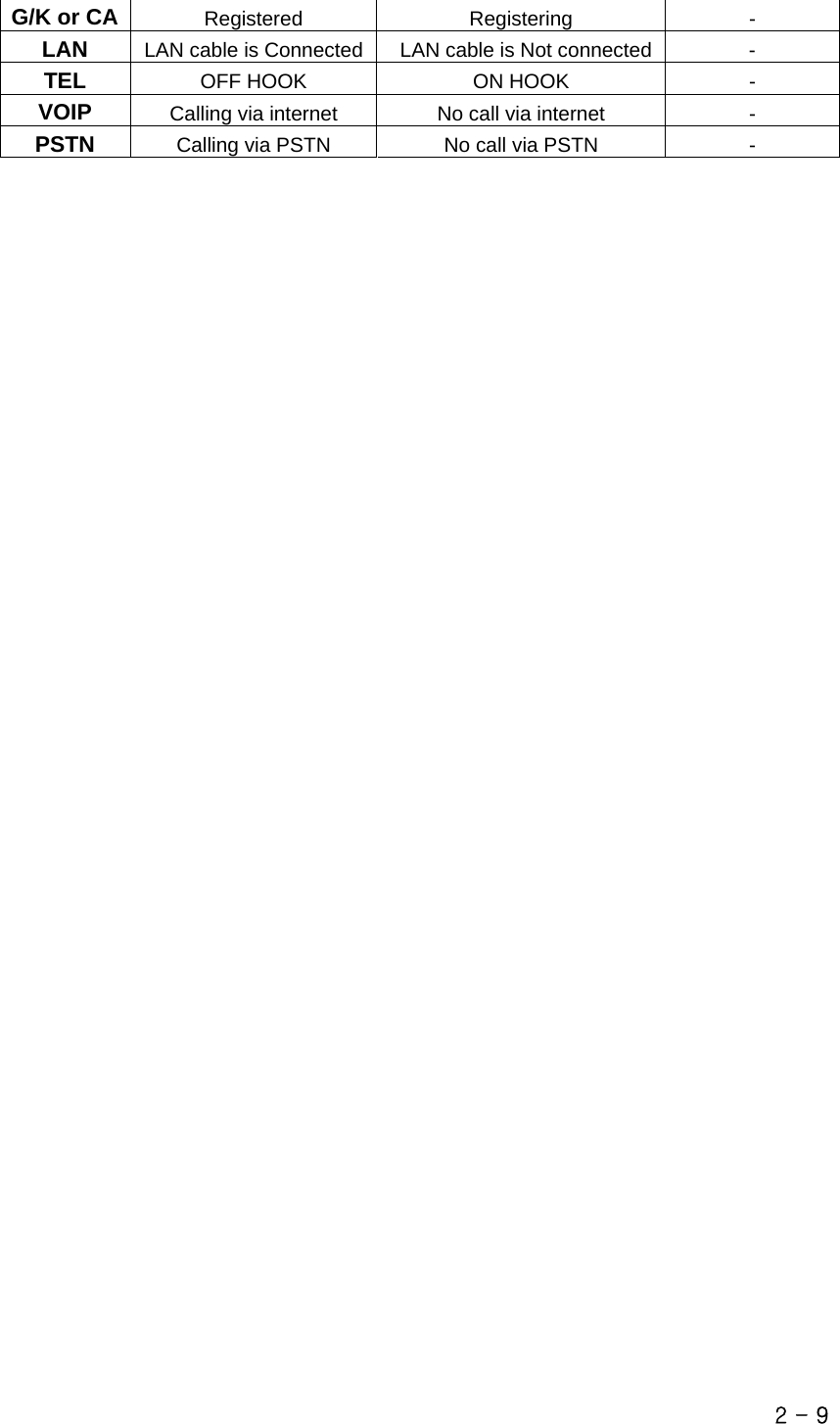
![2.3 Accessing the system with TELNET For VoIP Services, there are many configuration values you need to set. You may try telnet connection to set the configuration values. Detailed procedures are as follows: - Connect PC to PC port of DV-201DM - Open a “COMMAND PROMPT” Command Window. - Try pinging to 192.168.1.254. If you get response, you can proceed to the next step. - Type “telnet 192.168.1.254 6000”, and you can log-in to DV-201DM. - Try “root” for login name, “admin” for password. - Reply “DV_GW>”, you’ve accessed DV-201DM. [Example] Trying 192.168.1.254 (PORT: 6000)... Connected to 192.168.1.254... DV201DM Internet Phone Gateway System Made by Davolink,Inc. Motorola MPC850 SW: Release 1.00(2003-10-1 PM 06:23:26) HW: MPU 0.51 (1Ch FXS + 1Ch FXO) Now System Running... Login: root Password: ***** DV_GW> 2.3.1 Basic Commands DIR (or LS) “dir” is the same command as “ls” and displays the executable commands and sub-directory which can be run in the current directory. The sub-directory is displayed with “/” added after the last character to differentiate from the executable commands. The following example is the result after executing “dir” command on DV_GW> prompt, where DV_GW is system name. The capitalized letters in the directory name and command name is the minimum number of characters to be entered in changing a task directory or executing a command and they are used as abbreviations for a directory or a command. 2 - 35](https://usermanual.wiki/DAVOLINK/DV-201DM/User-Guide-409989-Page-51.png)
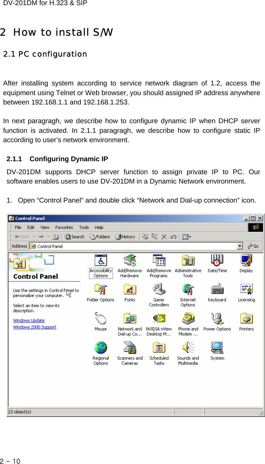
![DV-201DM for H.323 & SIP [Example] DV_GW> dir © SYstem/ COnfig/ Ftp_client/ Test/ Netutil/ STatistics/ Vocfile/ Debug/ Memory/ CD "cd" is a command to change the working directory. A directory you want to move can be given an direct path starting from a route directory or given a relative path based on the current directory. It is possible to change directory by typing the name of directory without “cd” command or by typing capitalized character of name of destination directory. Same results are displayed in case of typing “cd system” or in case of typing “system” or in case of typing “s” (minimized letter of destination directory “system”). If only “cd” without any character is typed, they can see root directory. The following example is an after executing “cd” command on root directory. [Example] DV_GW> cd system © DV_GW/SYSTEM> 2.3.2 IP Configuration 1. Command directory DV_GW/CONFIG/IP> 2. Command function These commands are used for setting NAT Mode, IP address, subnet mask, gateway, Ethernet address . 3. Available commands Commands Description SHOW Show IP parameters CHANGE Change IP parameters Ether set Set Ethernet address 2 - 36](https://usermanual.wiki/DAVOLINK/DV-201DM/User-Guide-409989-Page-52.png)
![SHOW This command display NAT Mode, IP address, subnet mask, and Ethernet address, which are required to perform LAN service and WAN service. Executing “show” at “DV_GW/CONFIG/IP)” prompt can see details. [Example] DV_GW/CONFIG/IP> show © -------- WAN Parameters -------------------------- NAT mode - Enable WAN IP Address - 0.0.0.0 WAN Subnet Mask - 0.0.0.0 WAN Gateway - 0.0.0.0 Ethernet Addr - 00:08:52:88:12:92 LAN IP Address - 192.168.2.12 LAN Subnet Mask - 255.255.255.240 LAN Gateway - 0.0.0.0 -------- DNS Parameters -------------------------- DNS Not Used -------------------------------------------------- CHANGE This command used for setting NAT mode, IP address, subnet mask, and Ethernet address. Details can be seen by executing “show” at “DV_GW/CONFIG/IP>” prompt. [Example] DV_GW/CONFIG/IP> change © -------- WAN Parameters -------------------------- NAT mode - Enable WAN IP Address - 0.0.0.0 WAN Subnet Mask - 0.0.0.0 WAN Gateway - 0.0.0.0 Ethernet Addr - 00:08:52:88:12:92 LAN IP Address - 192.168.2.12 LAN Subnet Mask - 255.255.255.240 LAN Gateway - 0.0.0.0 -------- DNS Parameters -------------------------- DNS Not Used -------------------------------------------------- 2 - 37](https://usermanual.wiki/DAVOLINK/DV-201DM/User-Guide-409989-Page-53.png)
![DV-201DM for H.323 & SIP 2.3.4 Routing Table Configuration 1. Command directory DV_GW/CONFIG/ROUTE> 2. Command function Manages route table required for call routing. 3. Available commands Commands Description Show Command to show prefix table Add Command to add numbers to route table required for call routing Del Command to delete numbers registered in prefix table SHOW This command is used to display numbers registered in prefix table to the console. When add command is successfully executed, the number is added in the blank space in the following figure. Executing “show” at “DV_GW/CONFIG/ROUTE” prompt shows current routing table. [Example] DV_GW/CONFIG/ROUTE> show © ==================================================================== PREFIX TABLE ==================================================================== INTF PORT NUMBERS TRNC PREFIX POSTFIX EXTRA_INFO ==================================================================== FXS 0 200 0 0.0.0.0 FXS 1 201 0 0.0.0.0 IP 0 ~ 0 0.0.0.0 ==================================================================== ADD 2 - 42](https://usermanual.wiki/DAVOLINK/DV-201DM/User-Guide-409989-Page-58.png)
![This command used for adding numbers required for call routing to the routing table. Executing “add” at “DV_GW/CONFIG/ROUTE)” prompt can see detailed usage [Example] DV_GW/CONFIG/ROUTE> add © ==================================================================== ADD Command Usage ==================================================================== add intf <port> nums <trnc> <pre> <post> <extra> ==================================================================== intf ; interface name (fxs, fxo, net) port ; port number of interface (0 ~ ) nums ; prefix numbers ('0' ~ '9','.','*','#','~','?',',',NULL, length: 20) ; '.' : virtual dial tone, ',' : pause(500ms) trnc ; the number of truncation (0 ~ 31) pre ; prefix number ('0' ~ '9',NULL) post ; postfix number ('0' ~ '9',NULL) extra ; extra-informations (hexa-decimal) ==================================================================== DV_GW/CONFIG/ROUTE> add fxs 0 3922241 0 © Prefix Table Add success DV_GW/CONFIG/ROUTE> add net 0 8~ 1 127.0.0.1 © Prefix Table Add success DEL This command used for deleting number from the routing table. Executing “del” at “DV_GW/CONFIG/ROUTE>” prompt can see detailed usage. [Example] DV_GW/CONFIG/ROUTE> del © ==================================================================== DEL Command Usage ==================================================================== del all|[intf <port> nums] ==================================================================== intf ; interface name (fxs, fxo, net) 2 - 43](https://usermanual.wiki/DAVOLINK/DV-201DM/User-Guide-409989-Page-59.png)
![DV-201DM for H.323 & SIP port ; port number of interface (0 ~ ) nums ; prefix numbers ('0' ~ '9','*','#','~','?',NULL) ==================================================================== DV_GW/CONFIG/ROUTE> del fxs 0 200 © Prefix Table Delete success 2.3.5 Address Configuration Commands 1. Command directory DV_GW/CONFIG/ADDRESS> 2. Command function This command is used for managing a specified port number on FXS interface. 3. Available commands Commands Description Show show registered addresses Myaddr register local addresses SHOW This command is used to display specified port number registered in address table. Executing “show” at “DV_GW/CONFIG/ADDRESS>” prompt shows current address table. [Example] DV_GW/CONFIG/ADDRESS> show © ========================================================== Address TABLE ========================================================== INTF PORT LOCAL-ADDR PEER-ADDR GROUP-PORT ========================================================== FXS 0 7183312 FXS 1 7183313 ========================================================== MYADDR This command is used to register specified port numbers that are used as calling party address in outgoing calls to track calls. Executing “myaddr” at “DV_GW/CONFIG /ADDRESS>” to see usage details. 2 - 44](https://usermanual.wiki/DAVOLINK/DV-201DM/User-Guide-409989-Page-60.png)
![[Example] DV_GW/CONFIG/ADDRESS> myaddr © =============================================================== MYADDR Command Usage =============================================================== myaddr intf <port> nums =============================================================== intf ; local interface name(fxs,fxo) port ; port number of interface (0 ~ ) nums ; destination address ('0' ~ '9','*','#',NULL) =============================================================== DV_GW/CONFIG/ADDRESS> myaddr fxs 0 7183312 © DV_GW/CONFIG/ADDRESS> myaddr fxs 0 null © DV_GW/CONFIG/ADDRESS> show © =============================================================== Address TABLE =============================================================== INTF PORT LOCAL-ADDR PEER-ADDR GROUP-PORT =============================================================== FXS 0 FXS 1 7183313 =============================================================== 2.3.6 VoIP Configuration Commands (H.323) 1. Command directory DV_GW/CONFIG/VOIP> 2. Command function This command displays and sets up all the parameters required for the H.323. Details can be seen by typing an appropriate command from the “DV_GW/CONFIG/VOIP>” prompt to verify it. Changes and verifies the parameters needed for H.323, the parameters are as follows; Parameter Description G/K Interface Mode Connection mode of G/K. E.164 Address IP address and Port number of the first G/K. H.323 ID IP address and Port number of the second G/K. Time out H.323 ID of the system H.323 Prefix Prefix to be registered to G/K. RAS ParametersRAS TTL Re-registration cycle (second) after first registration to G/K. 2 - 45](https://usermanual.wiki/DAVOLINK/DV-201DM/User-Guide-409989-Page-61.png)
![DV-201DM for H.323 & SIP Q.931 Call Signaling Channel Listen Port Q.931 Call Signaling Port number when called. Audio codec type Codec set used for a call set-up. Fast Connect Used Use or not of the fast-connect protocol H.245 DTMF Message Method of sending DTMF in a message format of H.245 Fast Audio Connect Use or not of the ring back tone from network in ALERT condition. Force RBT to network The generation mode of a ringing tone to IP network when the system has received an ALERT message. H.245 Tunneling Use or not of the H.245 tunneling. BRQ Used Use or not of the BRQ message. NAT Used Use or not of the NAT. Discard non-fast alert Function of neglecting an ALERT message in a condition that there is no audio information. Protocol Parameters Using H.245 start (outbound) Use or not of the H.245 channel when starting a call.RTP Parameters # Frame/Packet The numbers of frame per one IP packet. Manual RAS Config Manual RAS Use or not of a Manual RAS. 3. Available commands Commands Description SHOW Shows VOIP parameter. CONFIGURE Changes VOIP parameter. SHOW This command displays the set up value of the H.323 Parameter. For detailed example, execute “show” from the “DV_GW/CONFIG/VOIP>” prompt to verify it. [Example] DV_GW/CONFIG/VOIP> show © * RAS Parameters * ------------------------------------------------------------------ Gatekeeper not used. * Registration Numbers * ------------------------------------------------------------------- 200 201 202 203 204 205 206 207 2 - 46](https://usermanual.wiki/DAVOLINK/DV-201DM/User-Guide-409989-Page-62.png)
![------------------------------------------------------------------- * My H323ID * ------------------------------------------------------------------- DV116 ------------------------------------------------------------------- * Timeout * ------------------------------------------------------------------- RRQ timer mode : Received from G/K RAS response timeout : 20 sec RAS retry number : 2 Q.931 response timeout : 20 sec ------------------------------------------------------------------- * RAS TTL * ------------------------------------------------------------------- 700 ------------------------------------------------------------------- Press any key to continue * Protocol Parameters * ------------------------------------------------------------------- Q.931 Call Signalling Channel Listen Port : 1720 Fast Connect Used : Yes H.245 DTMF Message : Relay using using H245 UII.alphanume ric Fast Audio Connect : No Force RBT to Network : No Wait Alert Timer : 20000 msec H.245 Tunneling : No BRQ Used : No NAT Used : No Discard non-fast alert : No Open H.245 when conneted(outbound side) : No ------------------------------------------------------------------- Press any key to continue * RTP Parameters * ------------------------------------------------------------------- # Frame / Packet : 1 ------------------------------------------------------------------- CONFIGURE Sets the parameters related to RAS, Protocol, RTP and Manual RAS requested in H.323 protocol. [Example] DV_GW/CONFIG/VOIP> configure © 1 . RAS Config 2 . Protocol Config 3 . RTP Config 2 - 47](https://usermanual.wiki/DAVOLINK/DV-201DM/User-Guide-409989-Page-63.png)
![DV-201DM for H.323 & SIP 4 . Manual RAS Config 0 . Exit Select (0 ~ 4): 2.3.7 VoIP Configuration Commands (SIP) 1. Command directory DV_GW/CONFIG/SIP/CONF> 2. Command function This command displays and sets up all the parameters required for the SIP. Details can be seen by typing an appropriate command from the “DV_GW/CONFIG/SIP/CONF>” prompt to verify it. 3. Available commands Commands Description SHOW Command to show all the parameters required for the SIP. URLMODE Command to set URL mode(SIP or TEL) for peer UA. MYDOMAIN Command to set service domain name. MYTELNUM Command to set a telephone number assigned to FXS port 1. PSVNAME Command to set proxy server name. RGNAME Command to set registrar name. AREACODE Command to set area code. CONFAPPLY Command to restart SIP according to newly setting parameters. SHOW This command displays the set up value of the SIP Parameter. For detailed example, execute “show” from the “DV_GW/CONFIG/SIP/CONF>” prompt to verify it. [Example] DV_GW/CONFIG/SIP/CONF> show © SIP Configuration URL mode sip Register state C_Registered Call state INITIAL my domain davolink.co.kr 2 - 48](https://usermanual.wiki/DAVOLINK/DV-201DM/User-Guide-409989-Page-64.png)
![my ipaddr xxx.xxx.xxx.xxx my sip url sip:021234567@davolink.co.kr my port 5060 my transport udp Proxy server proxy-davolink.co.kr Server name Server port 5060 Server transport udp Registrar name proxy-davolink.co.kr Registrar port 8001 Registrar trans udp Register timer 3600 sec Payload type G723_63[004] G711U [000] G723_53[102] G711A [008] G729A [018] GSM [003] Encoding name G723_63[G723-63] G711U[PCMA] G729A[G729] G723_53[G723-53] G711A[PCMU] GSM[] Codec enabled G711U G711A G723_63 Areacode NONE UserID Password 2 - 49](https://usermanual.wiki/DAVOLINK/DV-201DM/User-Guide-409989-Page-65.png)
![compare this character column with the following character column. “ assword:", "assword?” z &C It is the expansion character regarding to command input prompt and DV-201DM compare this character column with the following character column. "> ", "# " "uthentication fail", "uthentication Fail", "nknown", "ogin incorrect" 3. Script command In DV201DM, the following command is provided for modification/confirmation of script. command description SHOW Display the current contents of script on screen. SETUP Access the menu for modifying setup script. DIAL Access the menu for modifying dial script. EXP Add/remove a character column to/from expansion character column. EX. 1) GW/CONFIG/MODEM> script © usage : script show|setup|dial|[exp add|del <name> <expand>] show - show current MODEM scripts setup - change script to initialize & setup MODEM dial - change script to dial to PSTN(ISP) exp - expand reserved script word (ex. &U usr) EX. 2) GW/CONFIG/MODEM> script show © ========== MODEM SCRIPT ========== setup : \N AT&F OK AT+GCI=61 OK ATPX4W1L3M1E0S95=47 OK AT\\N3B0 OK \N dial : \N ATD\T CONNECT \N &U \U &P \P &C PPP PPP \N ================================== EX. 3) GW/CONFIG/MODEM> script setup © [ \N AT&F OK AT+GCI=61 OK ATTX4W1L3M1E0S95=47 OK AT\\N3B0 OK \N ] enter setup script : < new script > 2 - 55](https://usermanual.wiki/DAVOLINK/DV-201DM/User-Guide-409989-Page-71.png)
![DV-201DM for H.323 & SIP EX. 4) GW/CONFIG/MODEM> script dial © [ \N ATD\T CONNECT \N &U \U &P \P &C PPP PPP \N ] enter dial script : < new script > EX. 5) GW/CONFIG/MODEM> script exp add &C $ © Script Expand added &C, $ GW/CONFIG/MODEM> script show © ========== MODEM SCRIPT ========== setup : \N AT&F OK AT+GCI=61 OK ATPX4W1L3M1E0S95=47 OK AT\\N3B0 OK \N dial : \N ATD\T CONNECT \N &U \U &P \P &C PPP PPP \N ================================== &C : $ ================================== EX. 6) GW/CONFIG/MODEM> script exp del &C $ © Script Expand deleted &C GW/CONFIG/MODEM> script show © ========== MODEM SCRIPT ========== setup : \N AT&F OK AT+GCI=61 OK ATPX4W1L3M1E0S95=47 OK AT\\N3B0 OK \N dial : \N ATD\T CONNECT \N &U \U &P \P &C PPP PPP \N ================================== 2 - 56](https://usermanual.wiki/DAVOLINK/DV-201DM/User-Guide-409989-Page-72.png)