DB ELETTRONICA TELECOMUNICAZIONI S P A MOZART50 50W FM BROADCAST TRANSMITTER User Manual Mozart series R1 0 3
DB ELETTRONICA TELECOMUNICAZIONI S.P.A. 50W FM BROADCAST TRANSMITTER Mozart series R1 0 3
UserManual.wiki
>
DB ELETTRONICA TELECOMUNICAZIONI S P A
>
MOZART50 User Manual
User Manual
Navigation menu
Upload a User Manual
Namespaces
Wiki Guide
HTML
PDF
Info
Views
User Manual
Discussion / Help
Navigation
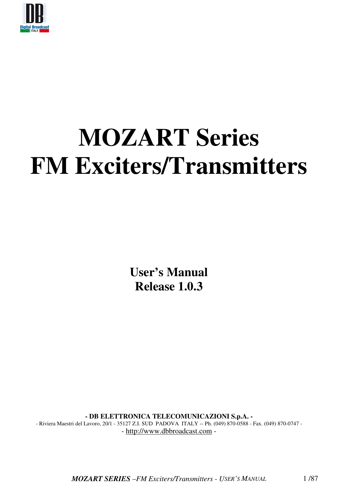

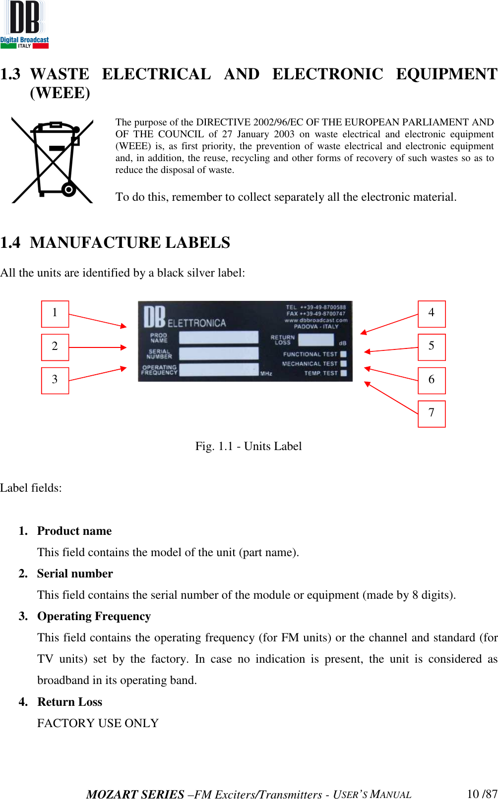

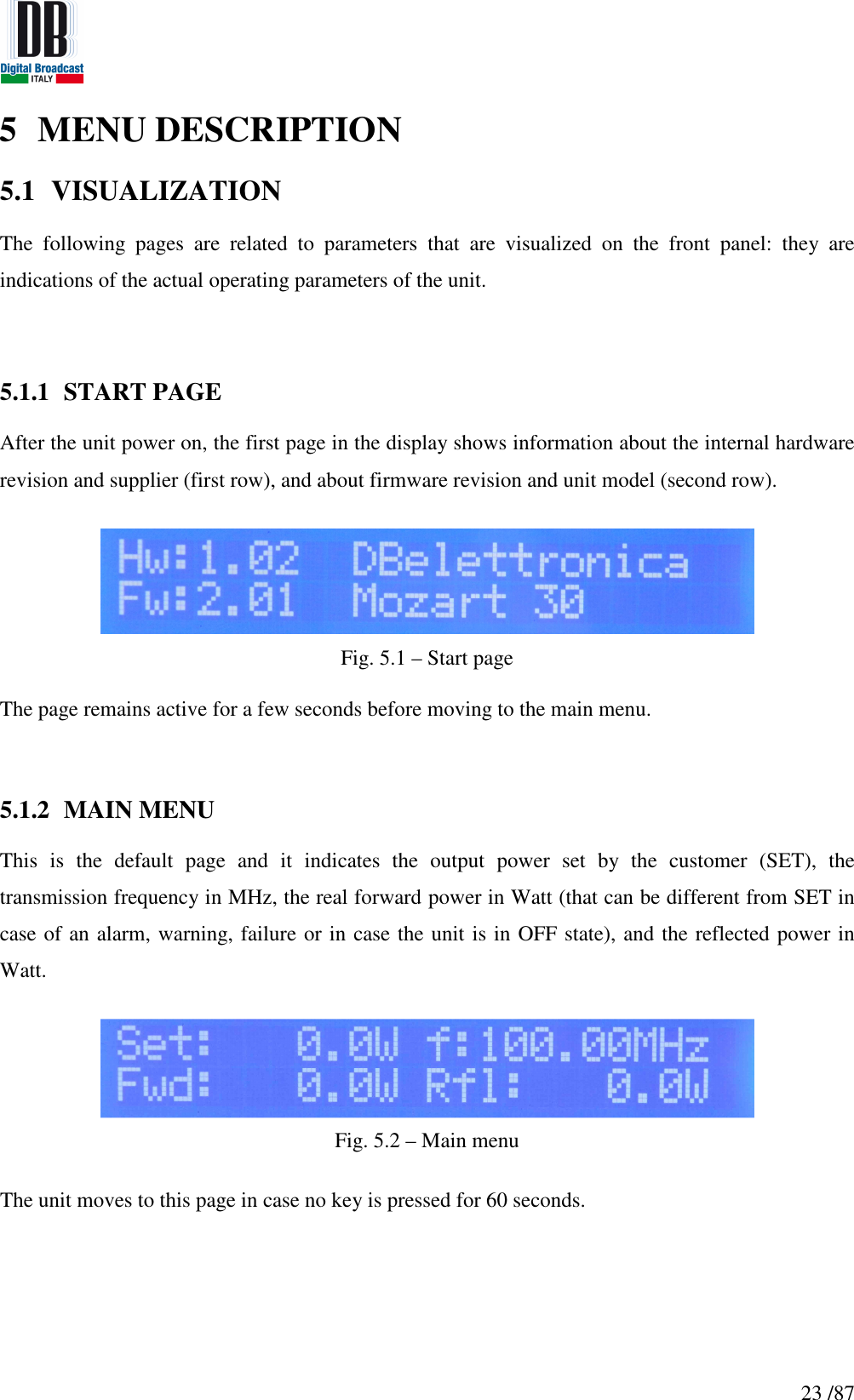
![24 /875.2 VMETERS AND INFO MENU In these menus it is possible to find the levels of the input channels, the internal voltages, currents, temperatures and the software/hardware revisions. In the Main Menu page press DOWN key to enter these pages and UP and DOWN keys to navigate in the sub-menus. [0] Main Page [1] Output Modulation [2] Left and Right channels input level [3] Left and Right AES-EBU channels input level [4] MPX External, RDS External input levels [5] SCA and AUX input levels [6] Internal voltages and current [7] Heatsink temperature [8] Device information Fig. 5.3 – Vmeters and Info menus flow graph](https://usermanual.wiki/DB-ELETTRONICA-TELECOMUNICAZIONI-S-P-A/MOZART50/User-Guide-2322969-Page-24.png)
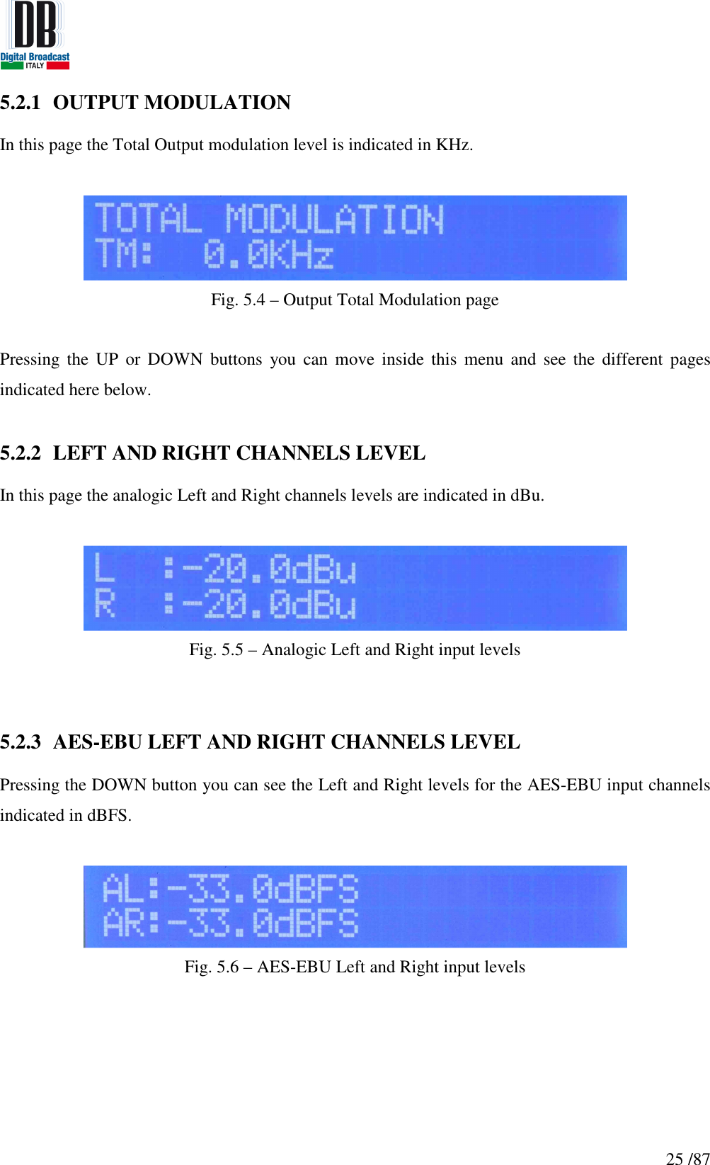
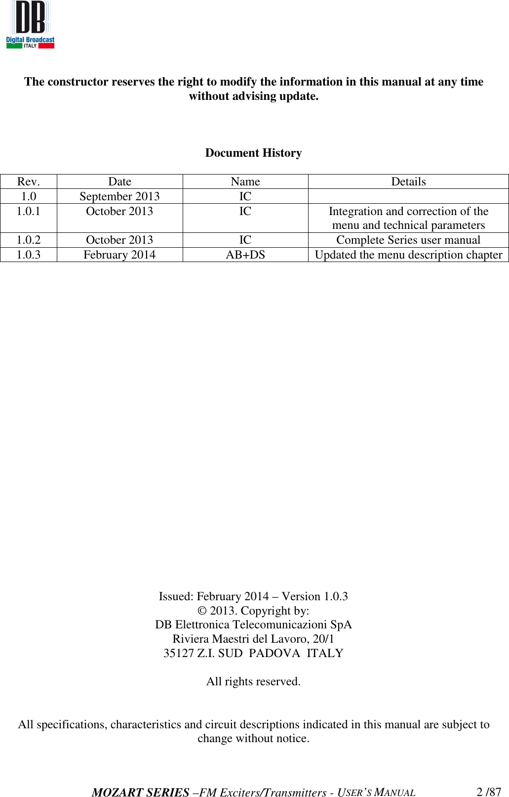
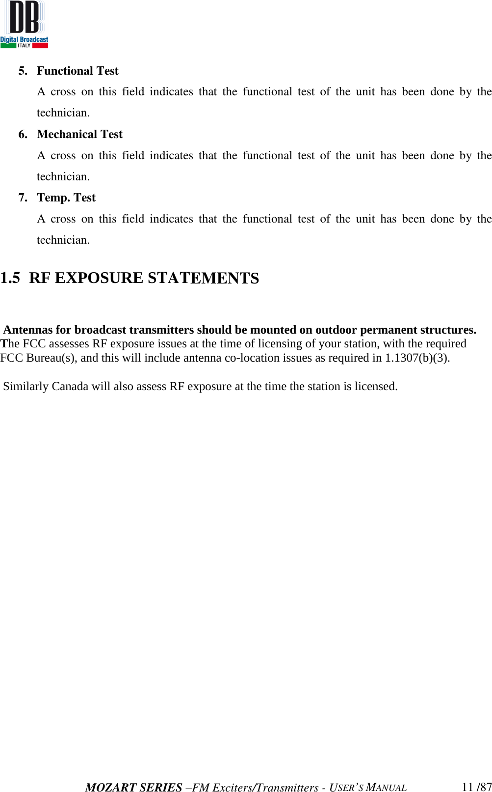
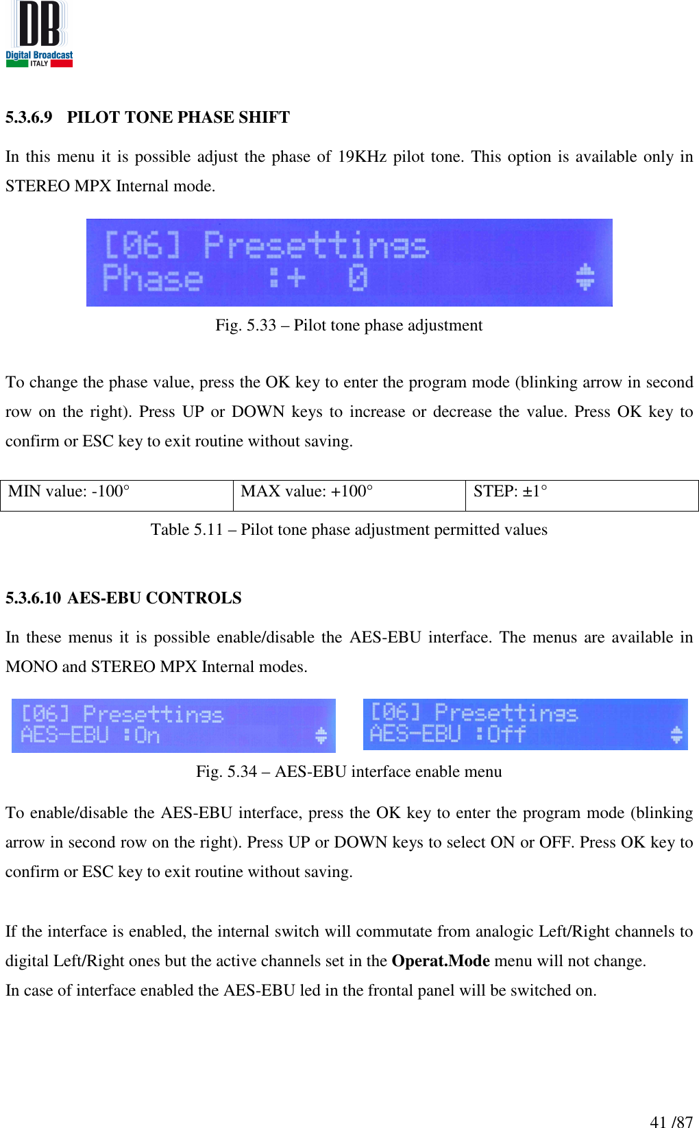
![28 /875.3 SETTINGS MENU The following pages are related to the unit main parameters. To navigate on Setting menu press LEFT or RIGHT key from Main Menu. In case sub-menu is present, an arrow pointing downwards will be showed in the second row on the right, press DOWN or UP to navigate on sub-menus. [0] Main Menu [1] Frequency [2] Setting Power [3] Operative Mode [4] Audio Selection [5] Sensitivity Set [6] Presettings [7] Alarms/Warnings [8] Memory Manage [9] History Log [10] Generals Fig. 5.12 – Setting menu flow graph](https://usermanual.wiki/DB-ELETTRONICA-TELECOMUNICAZIONI-S-P-A/MOZART50/User-Guide-2322969-Page-28.png)
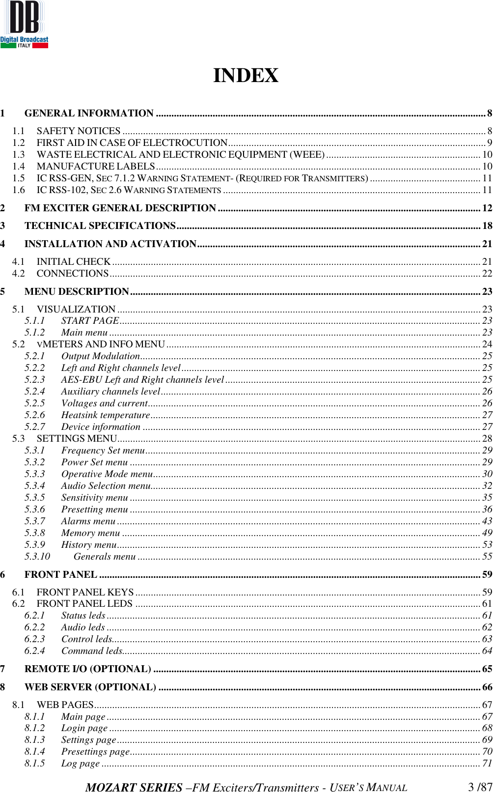
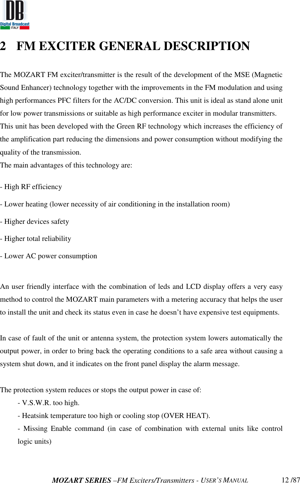
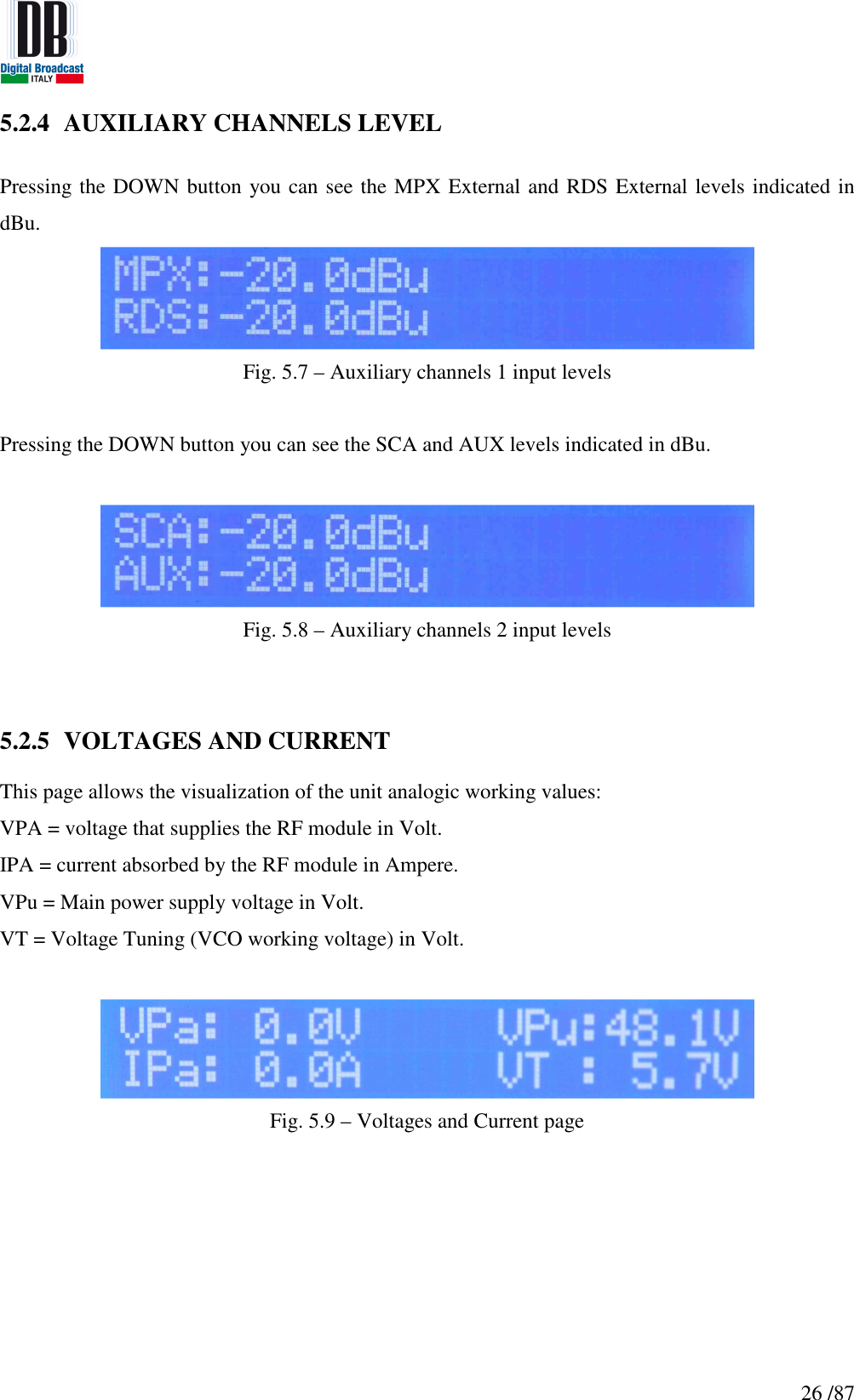
![31 /87 In case the AES-EBU is active (Presetting Menu), the enabled channel is relative to AES-EBU, please select AES-EBU:Off for using the analogic input channels. 5.3.3.2 STEREO ACTIVE In case the STEREO is active, in the Operative Mode is present a sub menu due to the possibilities to activate the auxiliary channels: [0] STEREO selection [1] Auxiliary channel RDS [2] Auxiliary channel SCA [3] Auxiliary channel AUX Fig. 5.17 – Operative Mode STEREO options Starting condition for STEREO selection and auxiliary channels, in case the mode is changed from MONO to STEREO, is always OFF. In the STEREO selection can be selected the MPX External (rear connector) or the MPX Internal (if Stereo Coder card is available) mode. Fig. 5.18 – Operative Mode STEREO MPX To activate the desired mode press the OK key to enter the program mode (blinking arrow in second row on the right). Press UP or DOWN keys to select the desired mode. Press OK key to confirm or ESC key to exit routine without saving.](https://usermanual.wiki/DB-ELETTRONICA-TELECOMUNICAZIONI-S-P-A/MOZART50/User-Guide-2322969-Page-31.png)
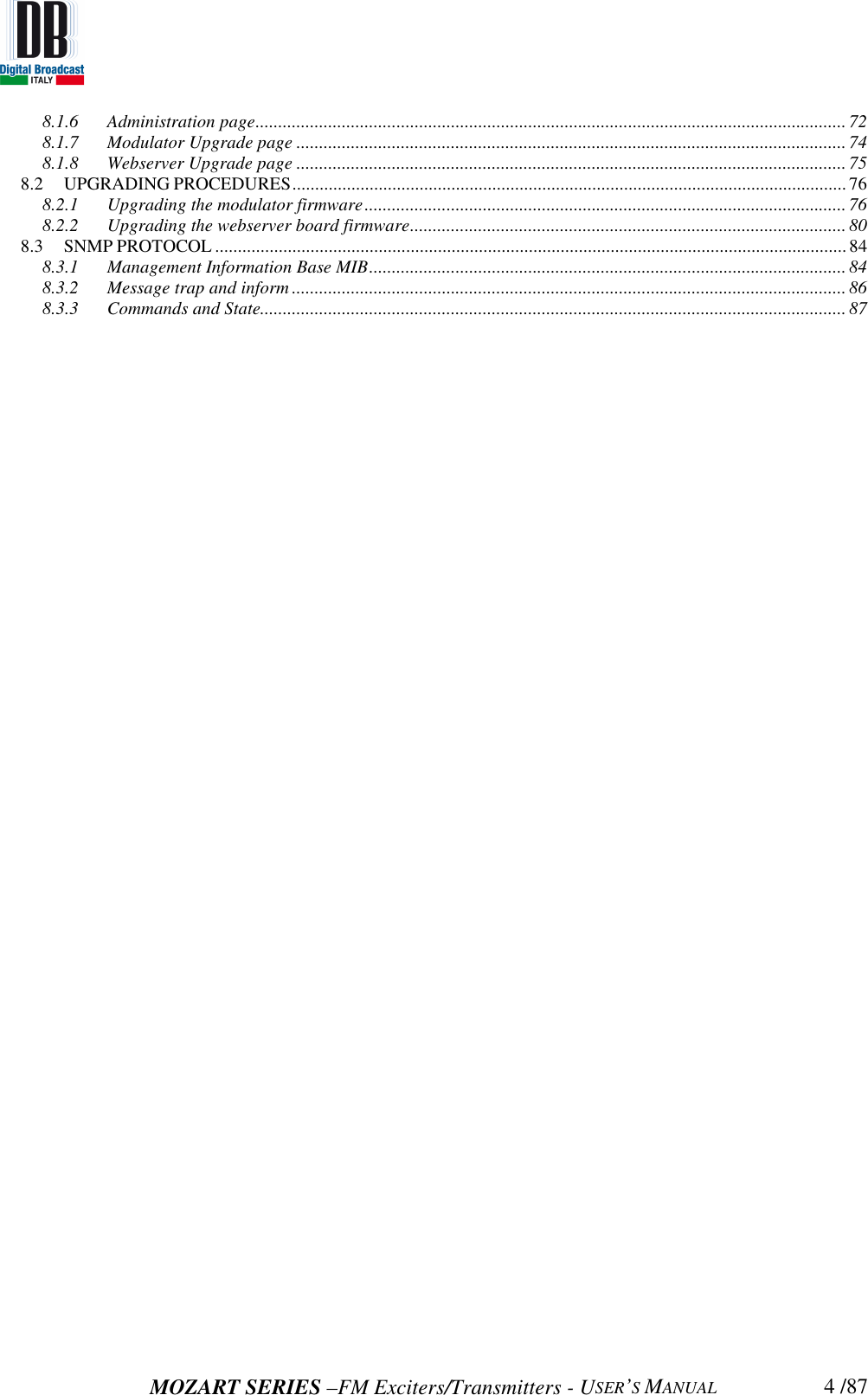
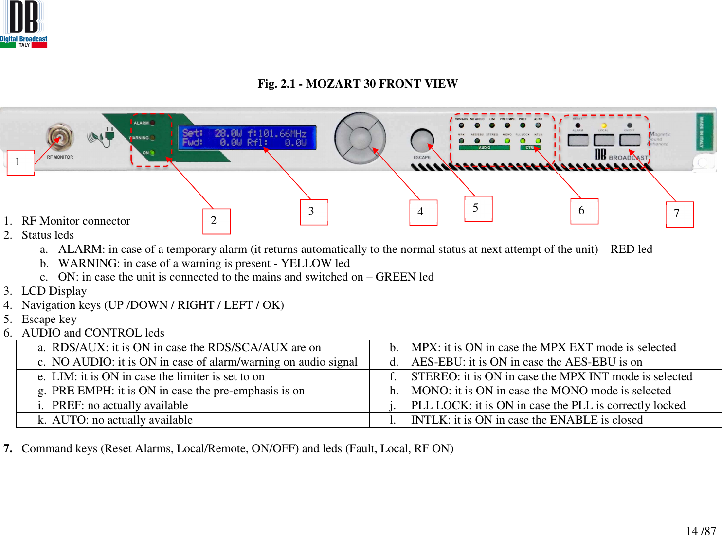
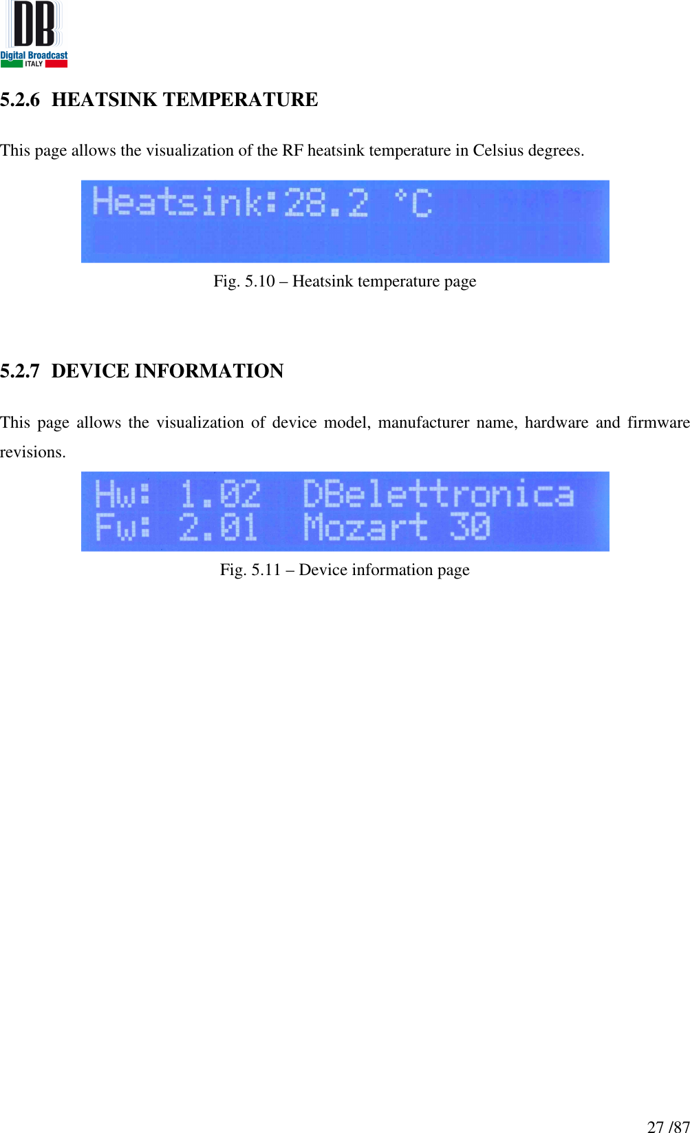
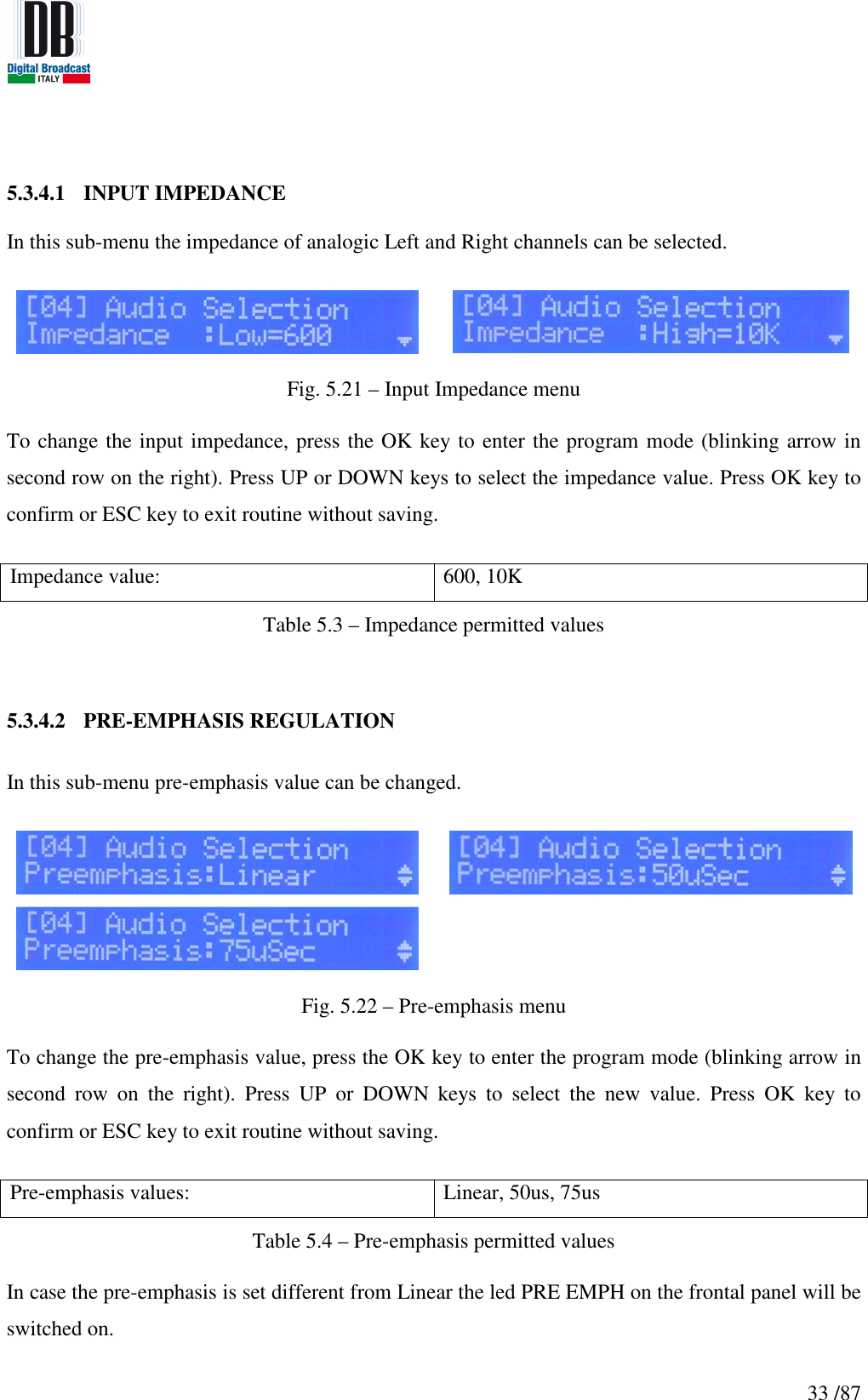
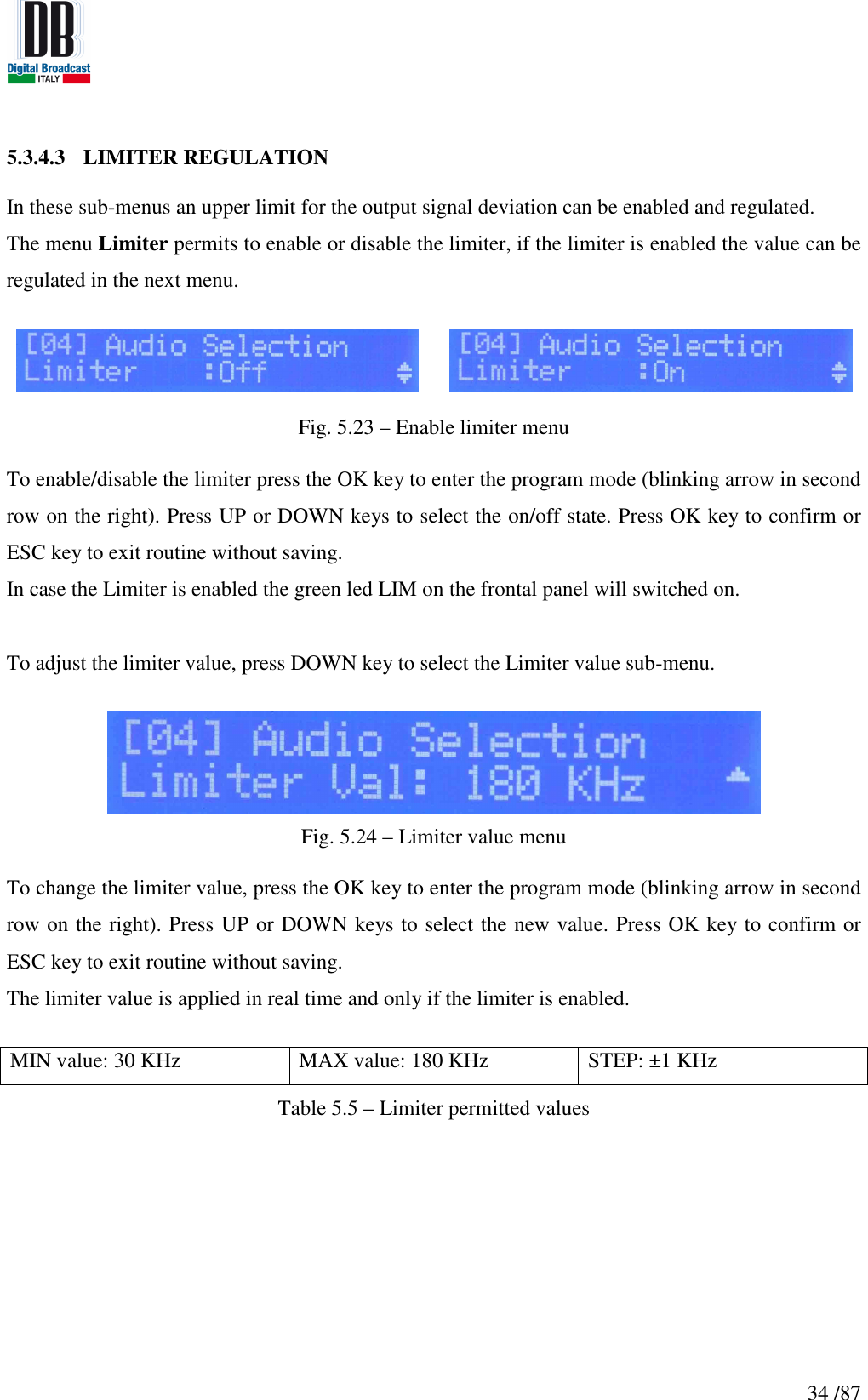
![32 /87 5.3.3.3 AUXILIARY CHANNELS To enable the auxiliary channels (available only in STEREO mode) navigate in the sub-menu with the UP and DOWN keys until the channel desired and press the OK key to enter the program mode (blinking arrow in second row on the right). Press UP or DOWN keys to change the ON/OFF state. Press OK key to confirm or ESC key to exit routine without saving. Fig. 5.19 – Auxiliary channels options In case one auxiliary channel is enabled the led RDS/AUX in the frontal panel will be switched on. 5.3.4 AUDIO SELECTION MENU In the Audio Selection sub-menu the regulations of input impedance, pre-emphasis and limiter are available. To navigate in the sub-menu press UP or DOWN keys. [0] Input Impedance [1] Preemphasis [2] Limiter [3] Limiter Value Fig. 5.20 – Audio Selection menu options](https://usermanual.wiki/DB-ELETTRONICA-TELECOMUNICAZIONI-S-P-A/MOZART50/User-Guide-2322969-Page-32.png)
![37 /87 5.3.6.2 PRESETTINGS IN MONO MODE [0] Mode Selection [1] Total Deviation Adjustment [2] AES-EBU Enable [3] AES-EBU Ratio Fig. 5.27 – Presetting MONO mode menu In MONO mode the options available are the fine adjustment of output signal deviation and the AES-EBU controls. To navigate in these menus press UP or DOWN keys. 5.3.6.3 PRESETTINGS IN STEREO MPX INTERNAL MODE [0] Mode Selection [1] Total Deviation Adjustment [2] RDS Deviation Adjustment [3] SCA Deviation Adjustment [4] AUX Deviation Adjustment [5] 19KHz/MPX Selection [6] Pilot Tone Deviation](https://usermanual.wiki/DB-ELETTRONICA-TELECOMUNICAZIONI-S-P-A/MOZART50/User-Guide-2322969-Page-37.png)
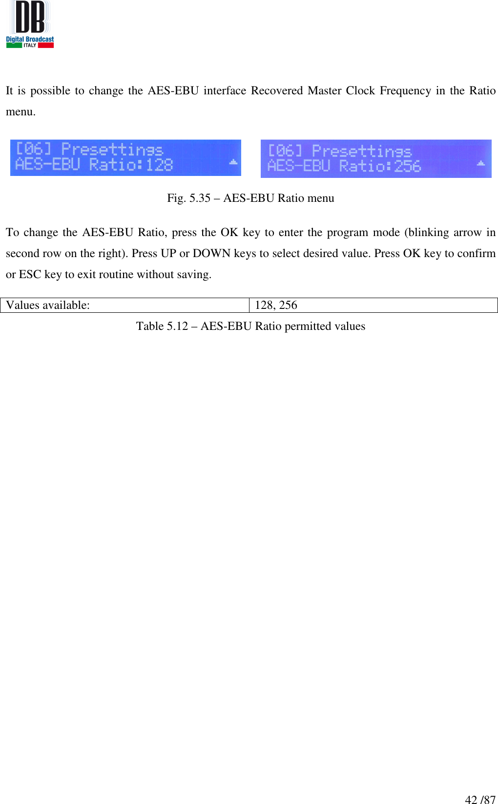
![38 /87 [7] Pilot Tone Phase Shift [8] AES-EBU Enable [9] AES-EBU Ratio Fig. 5.28 – Presetting STEREO MPX Int mode menu In STEREO mode MPX Internal enabled, the options available are the fine adjustment of output signal and auxiliary channels deviation, 19KHz/MPX output selection, Pilot Tone regulation and AES-EBU controls. To navigate in these menus press UP or DOWN keys. 5.3.6.4 PRESETTINGS IN STEREO MPX EXTERNAL MODE [0] Mode Selection [1] Total Deviation Adjustment [2] RDS Deviation Adjustment [3] SCA Deviation Adjustment [4] AUX Deviation Adjustment Table 5.7 - Presetting STEREO MPX Ext mode menu](https://usermanual.wiki/DB-ELETTRONICA-TELECOMUNICAZIONI-S-P-A/MOZART50/User-Guide-2322969-Page-38.png)
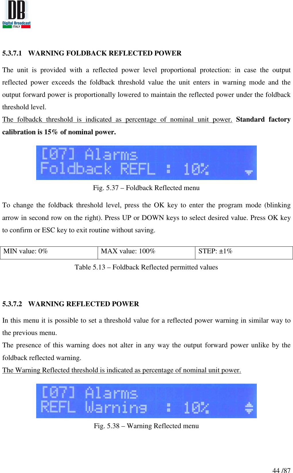
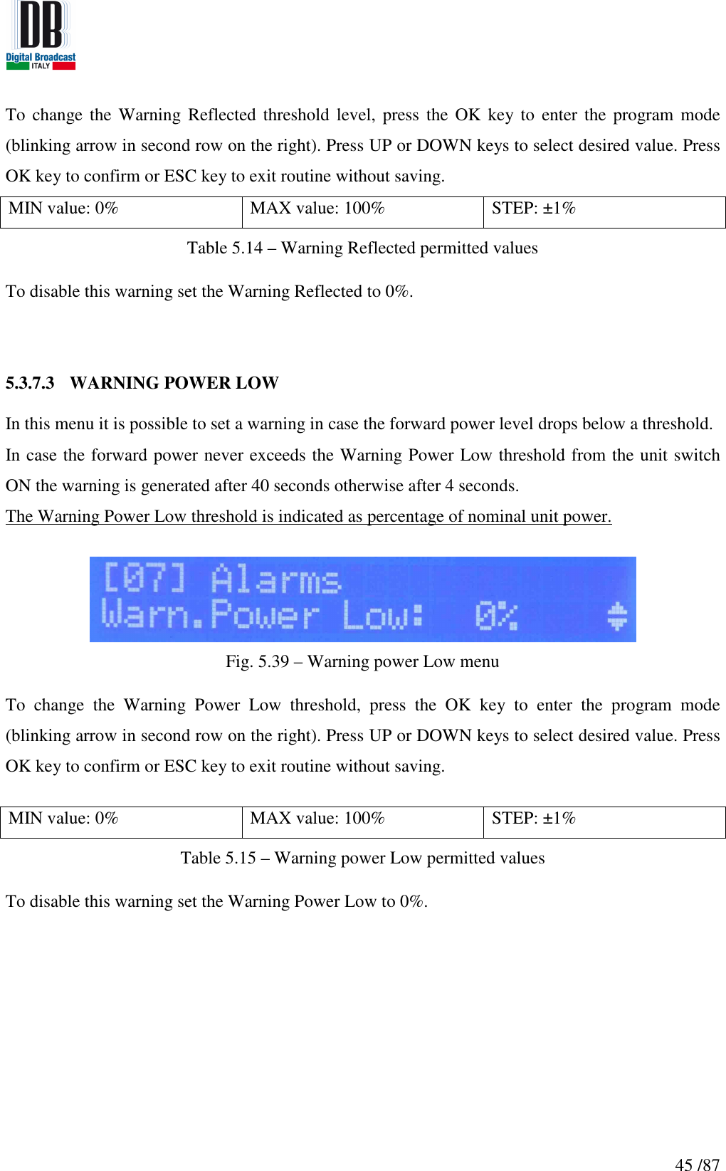
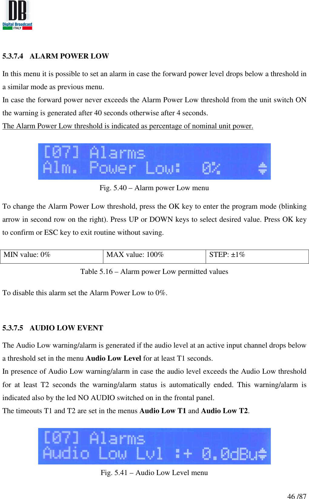
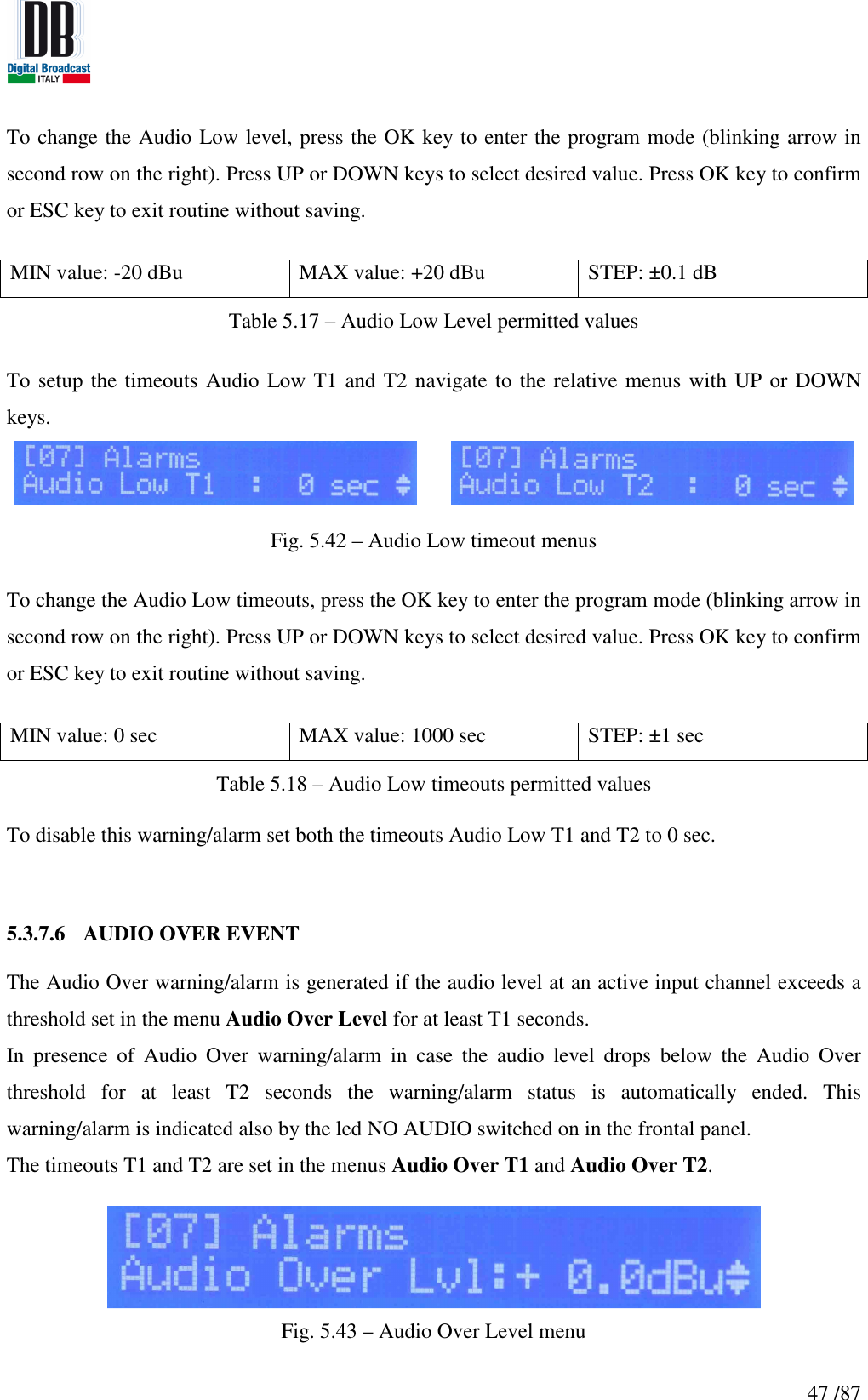
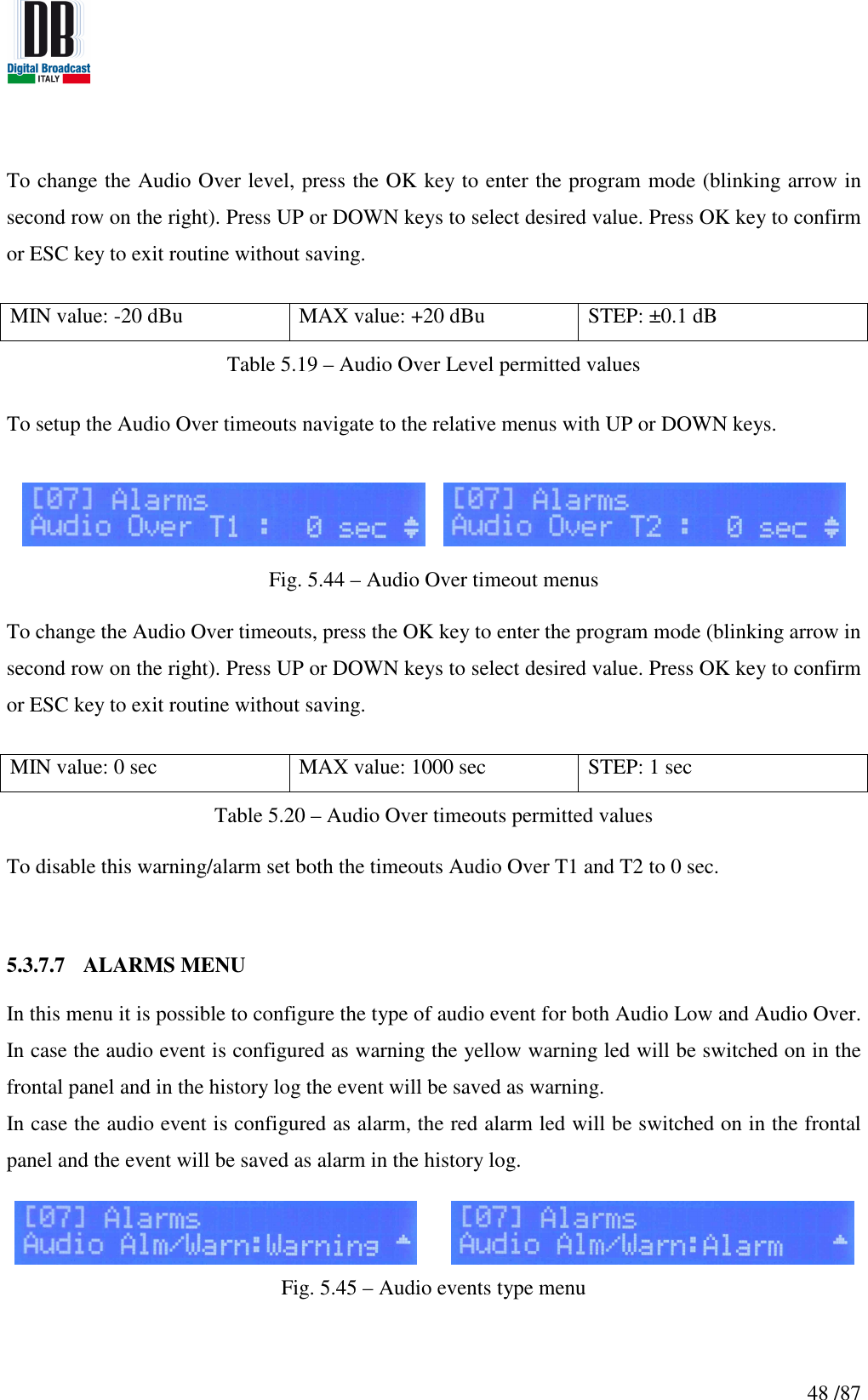
![43 /87 5.3.7 ALARMS MENU In these menus it is possible to set the thresholds of intervention of alarms/warnings. In case an event is verified an info will be saved in the history log and the warning or alarm led (depending on event type) will be switched on. To navigate in these menus press UP or DOWN keys. [0] Foldback Reflected [1] Warning Reflected [2] Warning Power Low [3] Alarm Power Low [4] Audio Low Level [5] Audio Low T1 [6] Audio Low T2 [7] Audio Over Level [8] Audio Over T1 [9] Audio Over T2 [10] Audio Event Type Fig. 5.36 – Alarms/Warnings menu flow graph](https://usermanual.wiki/DB-ELETTRONICA-TELECOMUNICAZIONI-S-P-A/MOZART50/User-Guide-2322969-Page-43.png)
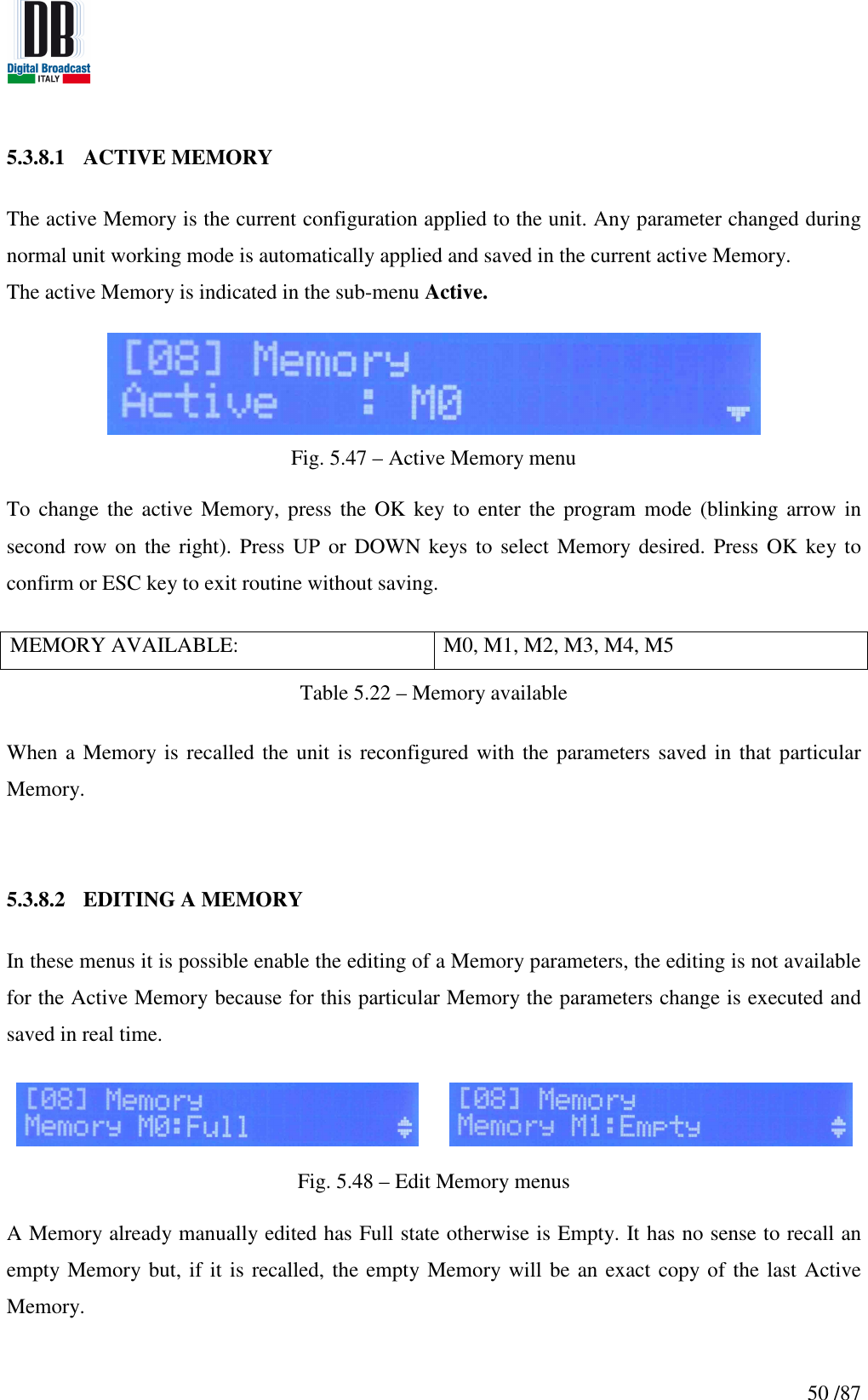
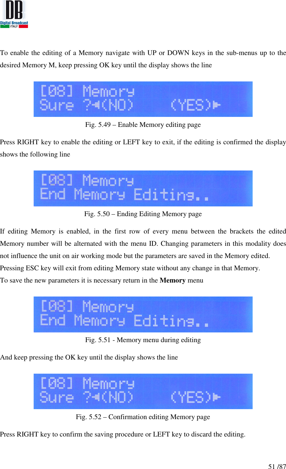
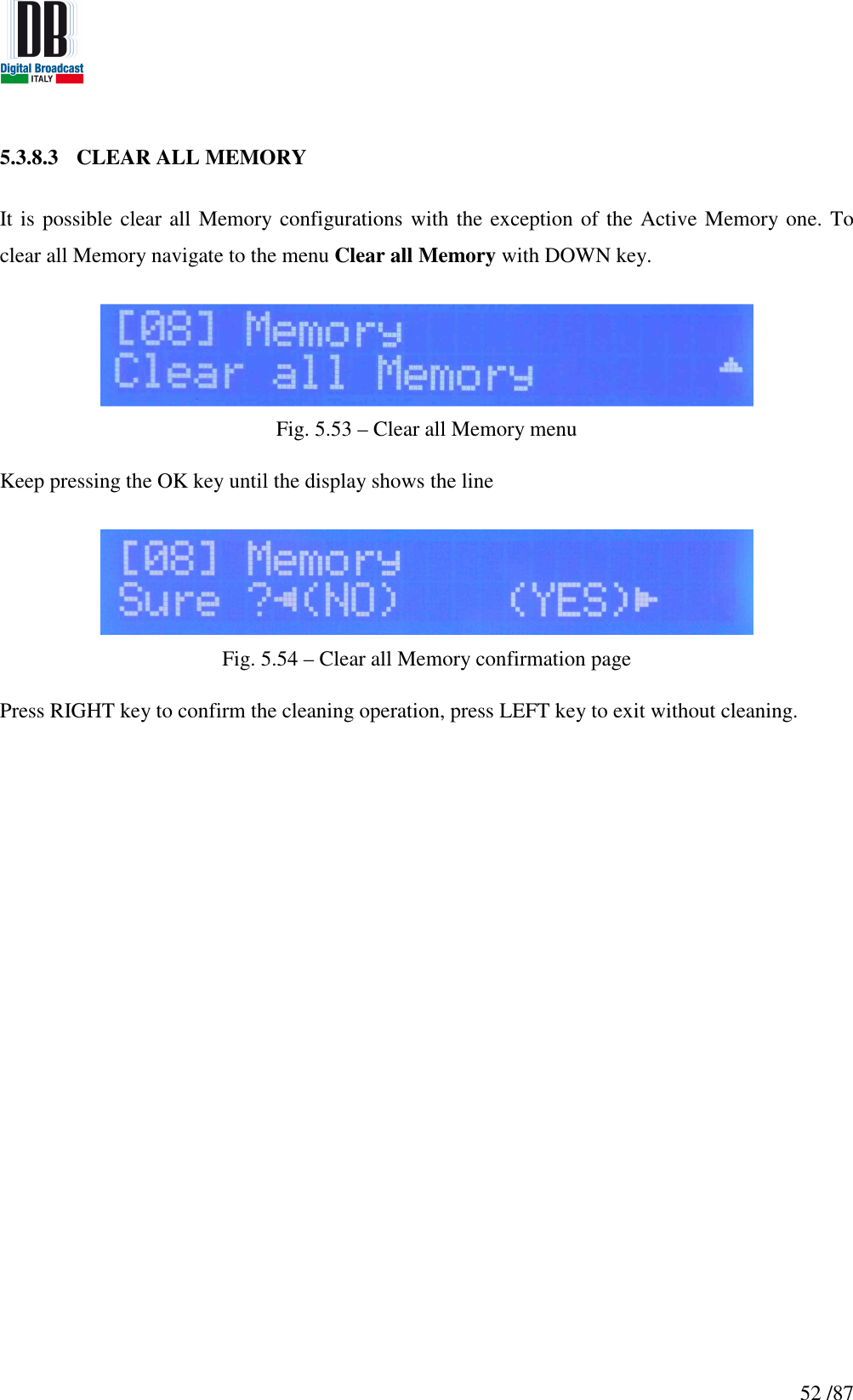
![49 /87 To change the Audio Event type, press the OK key to enter the program mode (blinking arrow in second row on the right). Press UP or DOWN keys to select type desired. Press OK key to confirm or ESC key to exit routine without saving. TYPE AVAILABLE: Warning, Alarm Table 5.21 – Audio events permitted types 5.3.8 MEMORY MENU The unit can be completely configured in 6 different modes (Memories) and these configurations are stored in the internal unit memory. [0] Active Memory [1] Edit Memory 0 [2] Edit Memory 1 [3] Edit Memory 2 [4] Edit Memory 3 [5] Edit Memory 4 [6] Edit Memory 5 [7] Clear Memory Fig. 5.46 – Memory menu flow graph](https://usermanual.wiki/DB-ELETTRONICA-TELECOMUNICAZIONI-S-P-A/MOZART50/User-Guide-2322969-Page-49.png)
![54 /87 Here below the complete list of events recognized is indicated: EVENT TYPE CODE Max Current ALARM 0001 Max Environment Temp ALARM 0002 - [Not used] 0003 [Not used] Foldback Reflected WARNING 0004 Reset INFO 0005 Max Heatsink Temp ALARM 0006 If Temperature > 68°C Max Supply Temp ALARM 0007 - [Not used] 0008 [Not used] Interlock Open WARNING 0009 Power On INFO 0010 Max Hardware Reflected ALARM 0011 Fan Warning WARNING 0012 Frequency Change INFO 0013 Change to Local INFO 0014 Change to Remote INFO 0015 Audio Low ALARM 0016 Alarm version Power Low ALARM 0017 Alarm version Switch ON INFO 0018 Switch OFF INFO 0019 Fault too many Alarms ALARM 0020 End PLL Unlock INFO 0021 PLL Unlock ALARM 0022 Audio Over ALARM 0023 Alarm version End Foldback Reflected INFO 0024 End Hardware Reflected INFO 0025 End Power Low INFO 0026 For Alarm version End Audio Low INFO 0027 For Alarm version End Audio Over INFO 0028 For Alarm version End Fan Warning INFO 0029 End Max Heatsink Temp INFO 0030 Fault Hardware Reflected ALARM 0031 Too many hardware reflected events Power Low WARNING 0032 Warning version RDS Alarm ALARM 0033 End RDS Alarm INFO 0034 Alarms Present ALARM 0035 At least 1 alarm present Alarms Absent INFO 0036 No alarm present Warnings Present INFO 0037 At least 1 warning present Warnings Absent INFO 0038 No warning present RF Present INFO 0039 If Pout > 10% of power set value RF Absent INFO 0040 If Pout < 10% of power set value - [Not used] 0041 [Not used] - [Not used] 0042 [Not used] Audio Low WARNING 0043 Warning version End Audio Low INFO 0044 For Warning version End Power Low INFO 0045 For Warning version Audio Over WARNING 0046 Warning version End Audio Over INFO 0047 For Warning version NTP Synchronization WARNING 0048 End NTP Synchronization INFO 0049 Warning Reflected WARNING 0050 End Warning Reflected INFO 0051 Table 5.23 – Events list](https://usermanual.wiki/DB-ELETTRONICA-TELECOMUNICAZIONI-S-P-A/MOZART50/User-Guide-2322969-Page-54.png)
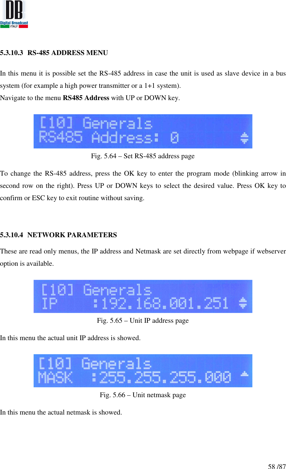
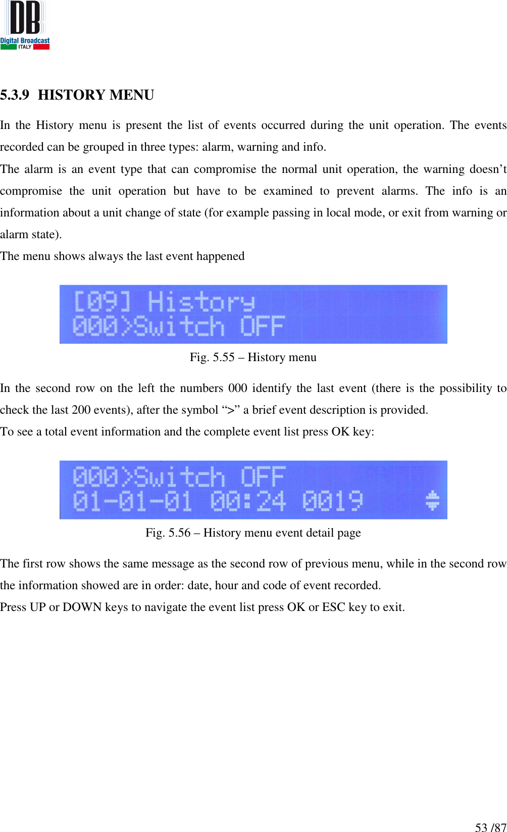
![55 /87 Every Warning and Alarm event has the corresponding END info event to indicate the time instant of ending from that particular warning/alarm condition. 5.3.10 GENERALS MENU The Generals menu contains options as time and date set, the RS-485 address, the IP address and netmask. [0] Set Hour [1] Set Minute [2] Set Second [3] Set Day [4] Set Month [5] Set Year [6] Set RS-485 address [7] IP address [8] Netmask Fig. 5.57 – Generals menu flow graph](https://usermanual.wiki/DB-ELETTRONICA-TELECOMUNICAZIONI-S-P-A/MOZART50/User-Guide-2322969-Page-55.png)