DEVILBISS Air Compressor Manual L0311218
102D-1 L0311218
User Manual: DEVILBISS DEVILBISS Air compressor Manual DEVILBISS Air compressor Owner's Manual, DEVILBISS Air compressor installation guides
Open the PDF directly: View PDF ![]() .
.
Page Count: 16
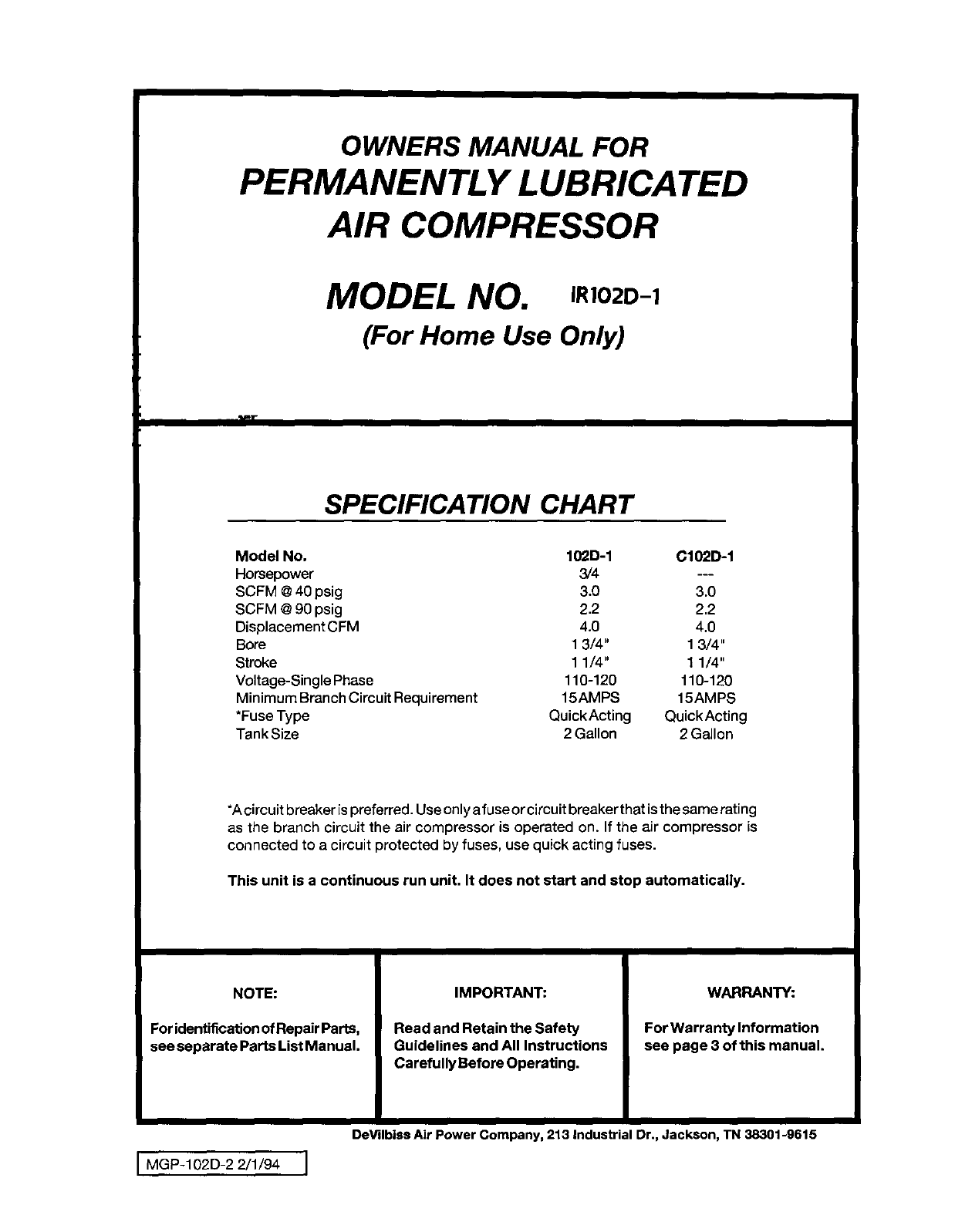
OWNERS MANUAL FOR
PERMANENTLY LUBRICATED
AIR COMPRESSOR
MODEL NO. ,RlO2D-1
(For Home Use Only)
tl'r
SPECIFICATION CHART
Model No. 102D-1 C10'2D-1
Horsepower 3/4 ---
SCFM @40 psig 3.0 3.0
SCFM @90 psig 2,2 2,2
Displacement CFM 4.0 4.0
Bore 1 3/4" 1 3/4"
Stroke 1 1/4" 1 1/4"
Voltage-Single Phase 110-120 110-120
Minimum Branch Circuit Requirement 15AMPS 15AMPS
*Fuse Type QuickActing QuickActing
Tank Size 2 Gallon 2 Gallon
*A circuitbreaker ispreferred. Useonly afuse or circuit breaker that is the same rating
as the branch circuit the air compressor is operated on. If the air compressor is
connected to a circuit protected by fuses, use quick acting fuses.
This unit is a continuous run unit. It does not start and stop automatically.
NOTE:
For identificationofRepair Parts,
see separate Parts List Manual.
IMPORTANT:
Read and Retain the Safety
Guidelines and All Instructions
Carefully Before Operating.
WARRANTY:
For Warranty Information
see page 3 of this manual.
IMGP-102D-2 2/1/94 I
DeVilbiss Air Power Company, 213 Industrial Dr., Jackson, TN 38301-9615
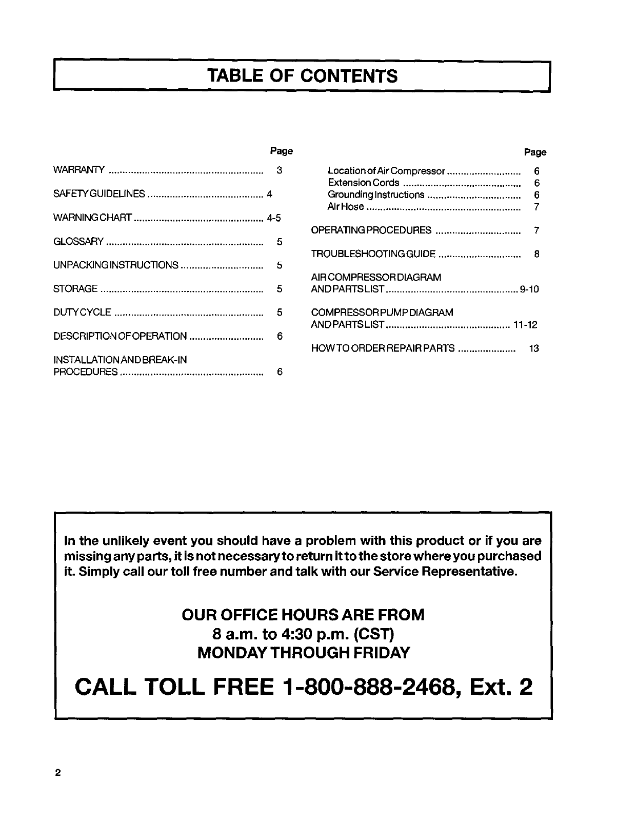
TABLE OF CONTENTS I
Page
WARRANTY ........................................................ 3
SAFETYGUIDELINES .......................................... 4
WARNING CHART ............................................... 4-5
GLOSSARY......................................................... 5
UNPACKINGINSTRUCTIONS .............................. 5
STORAGE ........................................................... 5
DUTYCYCLE ...................................................... 5
DESCRIPTION OFOPERATION ........................... 6
INSTALLATIONAN DBREAK-IN
PROCEDURES .................................................... 6
Page
Locationof Air Compressor ........................... 6
ExtensionCords ........................................... 6
GroundingInstructions.................................. 6
AirHose ........................................................ 7
OPERATINGPROCEDURES ............................... 7
TROUBLESHOOTINGGUIDE .............................. 8
AIRCOMPRESSOR DIAGRAM
AN D PARTSLIST ................................................ 9-10
COMPRESSOR PUMP DIAGRAM
AN D PARTSLIST ............................................. 11-12
HOWTO ORDER REPAIR PARTS ..................... 13
In the unlikely event you should have a problem with this product or if you are
missing a ny parts, it is not necessary to return it to the store where you purchased
it. Simply call our toll free number and talk with our Service Representative.
OUR OFFICE HOURS ARE FROM
8 a.m. to 4:30 p.m. (CST)
MONDAY THROUGH FRIDAY
CALL TOLL FREE 1-800-888-2468, Ext. 2
2
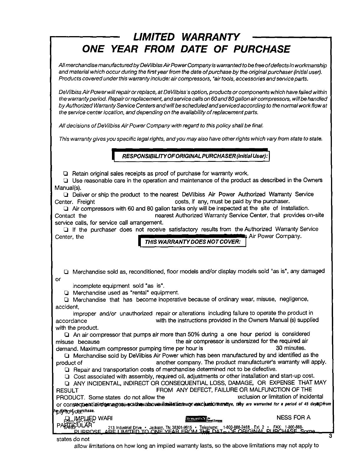
LIMITED WARRANTY
ONE YEAR FROM DATE OF PURCHASE
All merchandise manufactured by De VilbissAir Power Company is warranted to be free ofdefects in workmanship
and material which occur during the first year from the date of purchase by the original purchaser (initial user).
Products covered under this warranty include: air compressors, *airtools, accessories and serviceparts.
De Vilbiss Air Power will repair or replace, at DeVilbiss 's option, products or components which have failed within
the warranty period. Repair or replacement, and service calls on 60 and 80gallon air compressors, will be handled
by Authorized Warranty Service Centers and will be scheduled and serviced according to the normal work flow at
the service center location, and depending on the availability of replacement parts.
All decisions of DeVilbiss Air Power Company with regard to this policy shall be final
This warranty gives you specific legal rights, and you may also have other rights which vary from state to state.
iRESPONSIBILITYOFORIGINALPURCHASER(InitialUser):I
QRetain original sales receipts as proof of purchase for warranty work.
[3 Use reasonable care in the operation and maintenance of the product as described in the Owners
Manual(s).
{3 Deliver or ship the product to the nearest DeVilbiss Air Power Authorized Warranty Service
Center. Freight costs, if any, must be paid by the purchaser.
[3 Air compressors with 60 and 80 gallon tanks only will be inspected at the site of installation.
Contact the nearest Authorized Warranty Service Center, that provides on-site
service calls, for service call arrangement.
[3 If the purchaser does not receive satisfactory results from the Authorized Warranty Service
Center, the I I I I .... ;Air Power Company.
ITHIS WARRANTYDOESNOTCOVER: I
q
[3 Merchandise sold as, reconditioned, floor models and/or display models sold "as is", any damaged
or
incomplete equipment sold "as is".
[3 Merchandise used as "rental" equipment.
[3 Merchandise that has become inoperative because of ordinary wear, misuse, negligence,
accident,
improper and/or unauthorized repair or alterations including failure to operate the product in
accordance with the instructions provided in the Owners Manual (s) supplied
with the product.
[3 An air compressor that pumps air more than 50% during a one hour period is considered
misuse because the air compressor is undersized for the required air
demand. Maximum compressor pumping time per hour is 30 minutes.
[3 Merchandise sold by DeVilbiss Air Power which has been manufactured by and identified as the
product of another company. The product manufacturer's warranty will apply.
[3 Repair and transportation costs of merchandise determined not to be defective.
{3 Cost associated with assembly, required oil, adjustments or other installation and start-up cost.
{3 ANY INCIDENTAL, INDIRECT OR CONSEQUENTIAL LOSS, DAMAGE, OR EXPENSE THAT MAY
RESULT FROM ANY DEFECT, FAILURE OR MALFUNCTION OF THE
PRODUCT. Some states do not allow the ._xclusion or limitation of incidental
or con_e_lT._t_tiale_ien,_ve_bta'wsaJ_o_i|oldilati_tt_aqr_l_e, tbf_y are warranted for aperiod of 45 da_lp#or
WAR, MESSFORA
PA_'OI__ 213 IndustrialDrive •Jackson TN 38301-9615 • Telephone: 1o800_88-2468, Ext.2• FAX: 1-800-888-
states do not
allow limitations on how long an implied warranty lasts, so the above limitations may not apply to
3
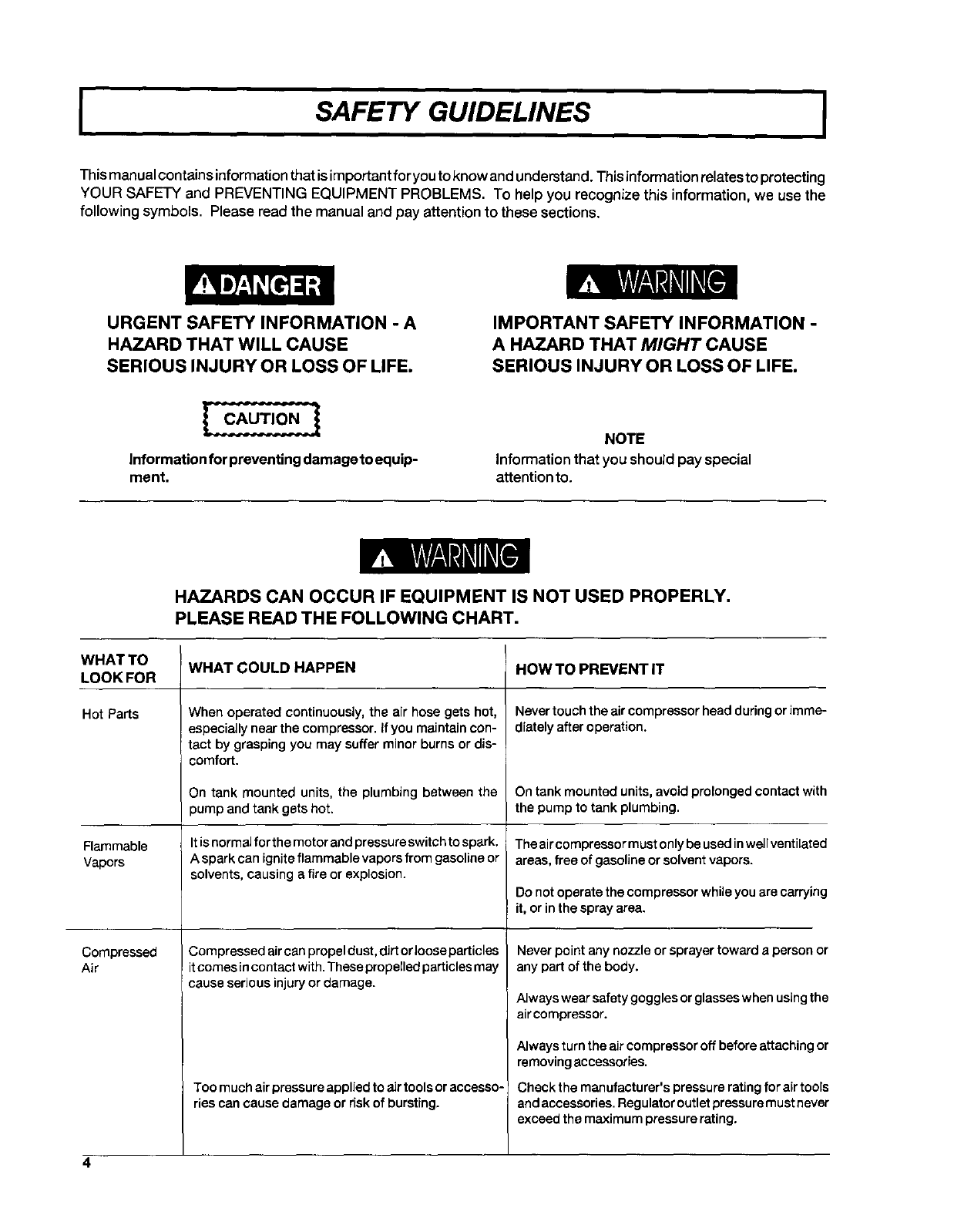
ISAFETY GUIDELINES I
Thismanual contain s information that is important for you to know and understand. This information relatesto protecting
YOUR SAFETY and PREVENTING EQUIPMENT PROBLEMS. To help you recognize this information, we use the
following symbols. Please read the manual and pay attention to these sections.
URGENT SAFETY INFORMATION -A
HAZARD THAT WILL CAUSE
SERIOUS INJURY OR LOSS OF LIFE.
IMPORTANT SAFETY INFORMATION -
A HAZARD THAT MIGHT CAUSE
SERIOUS INJURY OR LOSS OF LIFE.
Information for preventingdamage to equip-
ment,
NOTE
informationthat you should pay special
attentionto.
HAZARDS CAN OCCUR IF EQUIPMENT IS NOT USED PROPERLY.
PLEASE READ THE FOLLOWING CHART.
WHAT TO WHAT COULD HAPPEN HOW TO PREVENT IT
LOOK FOR
Hot Parts
Flammable
Vapors
Compressed
Air
When operated continuously, the air hose gets hot,
especially near the compressor. If you maintain con-
tact by grasping you may suffer minor burns or dis-
comfort.
On tank mounted units, the plumbing between the
pump and tank gets hot.
Itis normal for the motor and pressure switch to spark, i
A spark can ignite flammable vapors from gasoline or
solvents, causing a fire or explosion.
Corn pressed air canpropel dust, dJrtorloose particles
it comes in contact with. These propelledparticles may
cause serious injury or damage.
Too much airpressure appliedto air toolsoraccesso-
ripscan cause damage or risk of bursting,
Never touch the air compressor head during or imme-
diately after operation.
On tank mounted units, avoid prolonged contact with
the pump to tank plumbing.
Theaircompressormust onlybe used in wellventilated
areas, free of gasoline or solvent vapors.
Do not operate the compressor whileyou are carrying
it, or in the spray area.
Never point any nozzle or sprayer toward a person or
any part of the body.
Always wear safety goggles or glasses when using the
air compressor.
Always turn the air compressor off before attaching or
removingaccessories.
Check the manufacturer's pressure rating for air tools
and accessories. Regulatoroutletpressuremust never
exceed the maximum pressurerating.
4
WHAT TO WHAT COULD HAPPEN HOW TO PREVENT IT
LOOK FOR
EJectricity
Toxic Vapors
Unsuitable
Solvents
Your aircompressor is powered by electricity. Like any
other electrically powered device, if it is not used
properly it may cause electrical shock.
It is normal for compressed air to contain toxic or
irritating vapors. Such vapors are harmful if inhaled.
Certain materials you are spraying (like paint, weed
killer, sand or insecticide) can be harmful if you inhale
them.
The solvents 1,1,1 -Trichloroethane and Methylene
Chloride can chemically react with aluminum used in
paint spray guns, paint pumps, etc., and cause an
explosion. These solvents can also react with galva-
nized components and cause corrosion and weaken-
ing of parts. This does not affect your air compressor
- but it may affect the equipment being used.
AJways unplug the aircompressor prior to maintenance
or repair.
Never use the air compressor in the rain.
Always plug the cord into an erectrical outlet with the
specified voltage and adequate fuse protection.
Never directly inhale the compressed air produced by
this unit.
Read labels and safety data for all materials you spray.
Follow all safety precautions.
Read andfollowthe safetyinstructions provided onthe
label or safety data sheet for the material you are
spraying. Use a respirator mask if there is a chance of
inhaling anything you are spraying. Read all instruc-
tions.., be sure that the respirator mask is suitable for
your application.
Read the label or data sheetsupplied with the material
you intend to spray. If it contains the solvents listed do
not use accessories that contain aluminum or galva-
nized parts. You must either change the material you
intend to spray, or use only stainless steel spray equip-
ment.
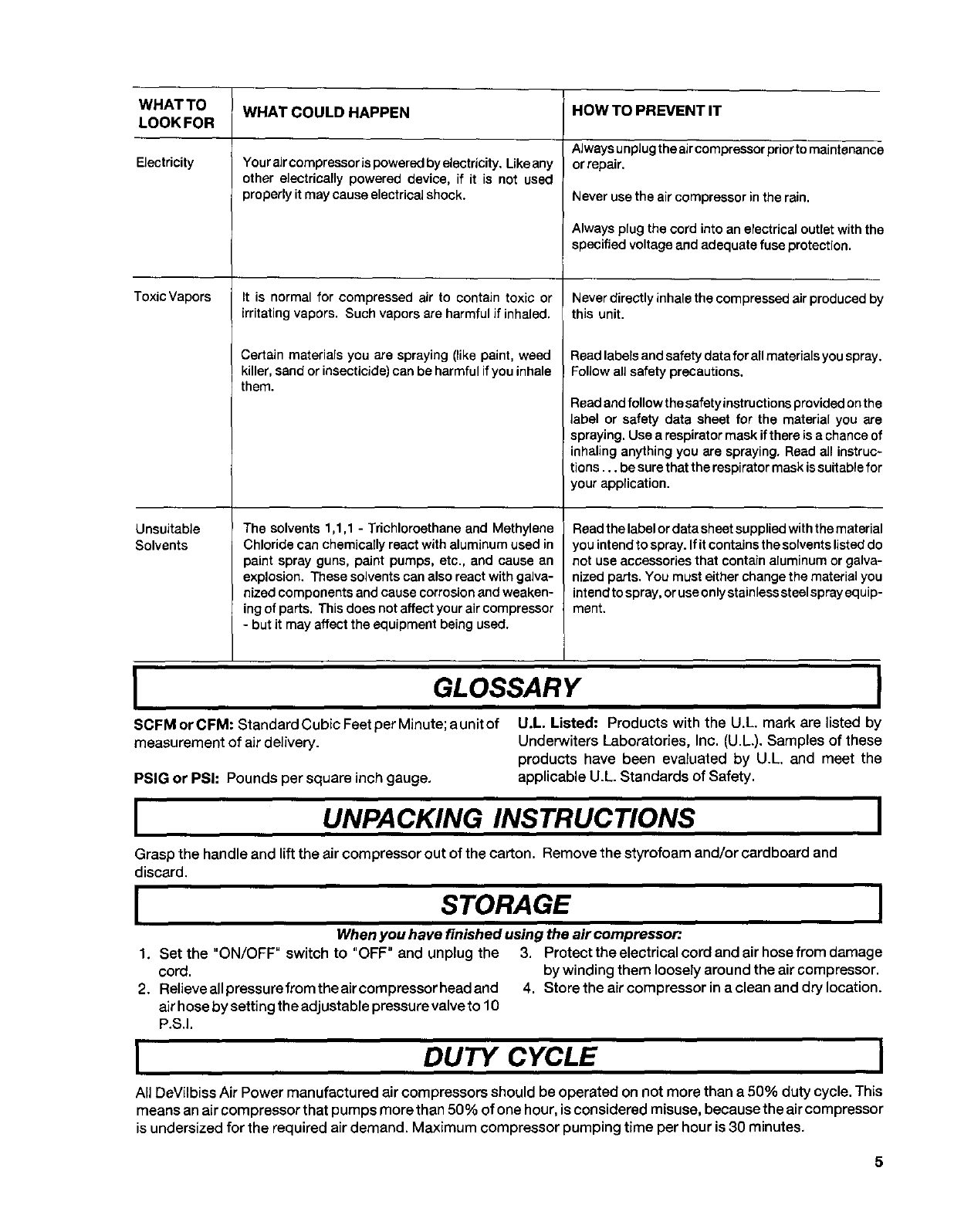
GLOSSARY I
SCFMorCFM: StandardCubicFeetperMinute;aunitof U.L. Listed: Products with the U.L mark are listed by
measurement of air delivery. Underwiters Laboratories, Inc. (U.L.). Samples of these
products have been evaluated by U.L. and meet the
PSIG or PSh Pounds per square inch gauge, applicable U.L. Standards of Safety.
IUNPACKING INSTRUCTIONS I
Grasp the handle and lift the air compressor out of the carton. Remove the styrofoam and/or cardboard and
discard.
ISTORAGE I
When you have finished using the air compressor
1. Set the "ON/OFF" switch to "OFF" and unplug the 3. Protecttheelectricalcordandairhosefromdamage
cord, by winding them loosely around the air compressor,
2. Relieveallpressurefromtheaircompressorheadand 4. Storetheaircompressorinacleananddrylocation.
air hose by setting the adjustable pressure valve to 10
P.S.I.
DUTY CYCLE
All DeVilbiss Air Power manufactured air compressors should be operated on not more than a 50% duty cycle. This
means an air compressor that pumps more than 50% of one hour, is considered misuse, because the air compressor
is undersized for the required air demand. Maximum compressor pumping time per hour is 30 minutes.
5
IDESCRIPTION OF OPERATION
Air Compressor Pump: To compress air, the piston
moves up and down in the cylinder. On the downstroke,
air isdrawn inthroughthe air intake muffler (valves).The
exhaust valve remains closed. On the upstroke of the
piston, air is compressed. The intake valves close and
compressed air is forced out through the exhaust valve
and thenthrough the air hose.
Adjustable Pressure Valve: The pressurevalvecontrols
the amount of pressuregoing from the air compressor to
the accessory. The pressureadjustingvalve can be used
to set approximate pressure between 10 and 125 P.S.I.
(125 P.S.I. is the highest pressure this compressor will
deliver).It is normal for the adiustable oressure valve to
release air during ooeration.
I
Accumulator Tank: Your accumulator tank isequipped
with a relief (pop-off) valve to prevent an over pressure
condition inthe tank. This 2 gallontank isnot designed to
store air, but rather to provide the additional volume of
compressed airnecessaryto operate a wide varietyof air
tools. When startingyour compressor, attach the tool to
the hose, set the pressureadjustingvalve at the required
pressure, wait a few moments untilthe tank fills withair.
You willknow the tank is filledwhen youhear airbleeding
through the pressure adjusting valve. Depending onthe
type and size of tool being used, you will occasionally
need to wait for the tank to refill before continuing. When
you are finsihed or changing tools, turn the compressor
switch off and set the pressure adjusting valve to 10 PSI
and wait for the tank to discharge completely.
ALWAYS SET THE PRESSURE VALVE AT OR
BELOW THE REQUIRED PRESSURE FOR THE
ACCESSORY BEING USED BEFORE START-
ING YOUR COMPRESSOR. FOR INFLATION
OR OTHER USES REQUIRING ACCURATE
PRESSURE, USEA PRESSURE GAUGE.
IINSTALLATION AND BREAK-IN PROCEDURES
Location of the Air Compressor
Your compressor comes to you completely assembled
and ready for use. Operate the air compressor in a dry,
clean, cool and well ventilatedarea. The air compressor
pump and case are designed to allowfor proper cooling.
Clean or blow off dust or dirt that collects on the air
compressor. A clean air compressor runs cooler and
provides Iongerservice.The ventilationopeningsonyour
air compressor are necessaryto maintain properoperat-
ingtemperature. Do notplaceragsorother containerson
or nearthese openings.
Extension Cords
use extra air hose instead of an extensioncord to avoid
voltage drop and power lossto the motor.
If an extension cord must be used, be sure it is:
•a3-wire extension cord that has a 3-blade grounding
plug, and a3-slot receptacle that will accept the plug on
the compressor
• in good condition
• no longer than 50 feet
• 14gauge (AWG) or larger. (Wire size increases as gauge
number decreases.) 12AWG, 10AWG and8 AWG may
also be used. DO NOT USE 16 OR 18 AWG.
GROUNDING INSTRUCTIONS
RISK OF ELECTRICAL SHOCKI In the event of a
short circuit, grounding reduces the riskof shock by
providing an escape wire for the electdc current.
This air compressor must be properly grounded.
The aircompressor is equipped with a cord having a
grounding wire with an appropriate grounding plug.
The plug must be used with an outlet that has been
installed and grounded in accordance with all local
codes and ordinances. The outlet must have the same
configuration as the plug. See illustration. DO NOT
USE AN ADAPTER.
Inspectthe plug and cord before each use. Do notuse if
there are signs of damage.
IMPROPER GROUNDING CAN RESULT IN ELEC-
TRICAL SHOCK.
6
IINSTALLATION AND BREAK-IN PROCEDURES I
Do not modify the plug that has been provided. If it
does not fit the available outlet, the correct outlet
should be installed by a qualified electrician.
If repairing or replacing cord or plug, the grounding
wire must be kept separate from the current-carrying
wires. Never connect the grounding wire to a flat blade
plug terminal. The grounding wire has insulation with
an outer surface that is green - with or without yellow
stripes.
If these grounding instructions are notcompletely
understood, or if in doubt as to whether the compres-
sor is properly grounded, have the installation checked
by a qualified electrician.
Air Hose
The airhoseattached to you rcomporessor has an integral
pressure adjusting valve at the working end of the hose.
Should service or replacement be required, make sure that
the pressure adjusting valve is present inthe air hose line.
DONOTREPLACE THE HOSE WITH STANDARD HOSE
THAT IS NOT EQUIPPED WITH THE PRES-
SURE ADJUSTING VALVE.
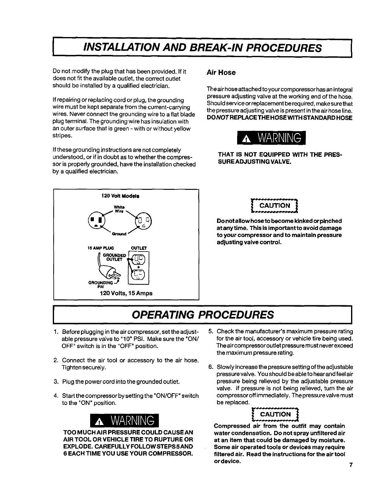
120VoltModels
White
lS AMP PLUG OUTLET
_E_" _GROUNDED
GROUNDING .jI _
PIN
120 Volts, 15 Amps
Do notallow hose to become kinked or pinched
at any time. This is importantto avoid damage
to your compressor and to maintain pressure
adjusting valve control.
IOPERATING PROCEDURES
1. Before plugging inthe air compressor, set the adjust-
able pressure valve to "10" PSI. Make sure the "ON/
OFF" switch is in the "OFF" position.
2. Connect the air tool or accessory to the air hose.
Tighten securely.
3. Plug the power cord into the grounded outlet.
4. Start the compressor by setting the "ON/OFF" switch
to the "ON" position.
TOO M UCH AIR PRESSURE COULD CAUSE AN
AIR TOOL OR VEHICLE TIRE TO RUPTURE OR
EXPLODE. CAREFULLY FOLLOWSTEPS 5AND
6 EACH TIME YOU USE YOUR COMPRESSOR.
5, Check the manufacturer's maximum pressure rating
for the air tool, accessory or vehicle tire being used.
The aircompressoroutlet pressure must never exceed
the maximum pressure rating.
6. Slowly increasethe pressure settingof the adjustable
pressure valve. You should be ableto hear and feel air
pressure being relieved by the adjustable pressure
valve. If pressure is not being relieved, turn the air
compressor offimmediately. The pressurevalvemust
be replaced.
Compressed air from the outfit may contain
water condensation. Do not spray unfiltered air
at an item that could be damaged by moisture,
Some air operated tools or devices may require
filtered air. Read the instructions for the air tool
ordevice. 7
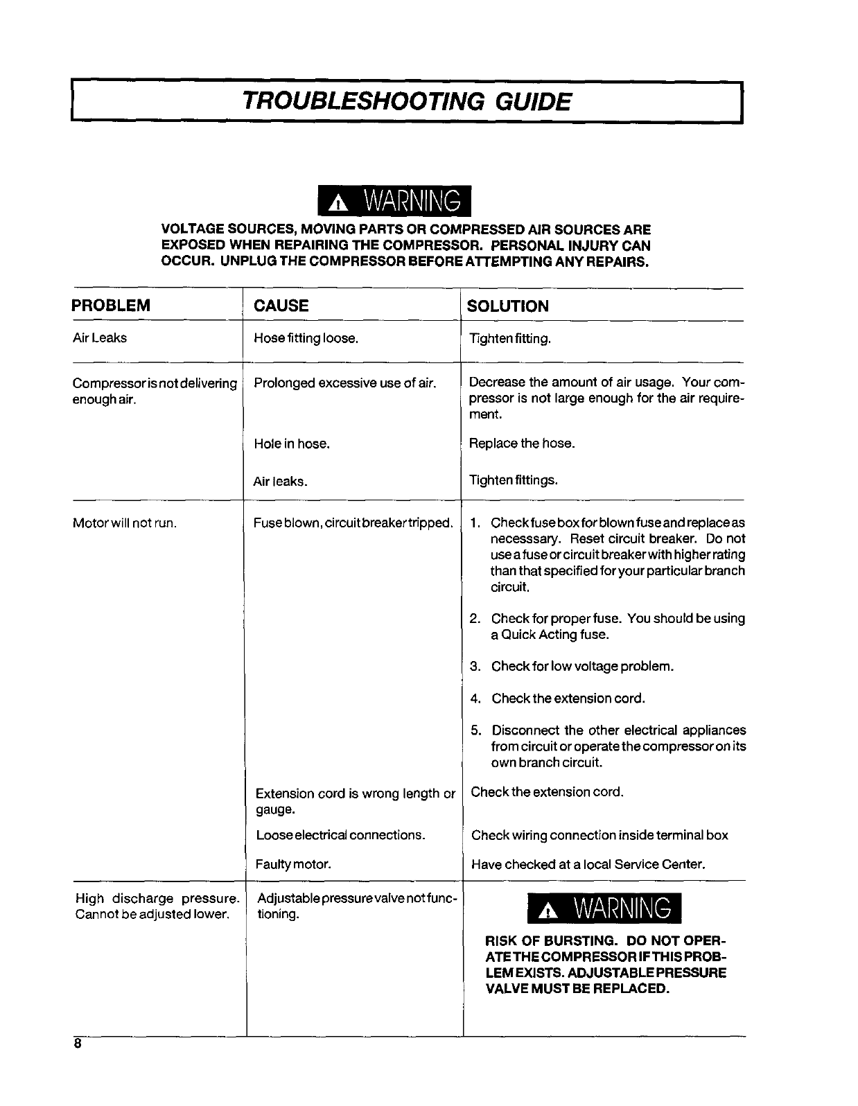
TROUBLESHOOTING GUIDE I
VOLTAGE SOURCES, MOVING PARTS OR COMPRESSED AIR SOURCES ARE
EXPOSED WHEN REPAIRING THE COMPRESSOR. PERSONAL INJURY CAN
OCCUR. UNPLUG THE COMPRESSOR BEFORE AI-rEMPTING ANY REPAIRS.
PROBLEM CAUSE SOLUTION
Air Leaks Hose fitting loose. Tighten fitting.
Prolonged excessive use of air.Compressor isnot delivering
enough air.
Motor will not run.
High discharge pressure.
Cannot be adjusted lower.
Hole in hose.
Air leaks.
Fuse blown, circuit breaker tripped.
Extension cord is wrong length or
gauge.
Loose electrical connections.
Faultymotor.
Adjustable pressu revalve not func-
tioning.
Decrease the amount of air usage. Your com-
3ressor is not large enough for the air require-
meat.
Replace the hose.
Tighten fittings.
1, Check fuse box for blown fuse andreplace as
necesssary. Reset circuit breaker. Do not
use afuse or circuit breaker with higher rating
than that specified for your particular branch
circuit.
2. Check for proper fuse. You should be using
a Quick Acting fuse.
3. Check for low voltage problem.
4. Check the extension cord.
5. Disconnect the other electrical appliances
from circuit or operate the compressor on its
own branch circuit.
Check the extension cord.
Check wiring connection inside terminal box
Have checked at a local Service Center.
RISK OF BURSTING. DO NOT OPER-
ATE THE COMPRESSOR IF THIS PROB-
LEM EXISTS. ADJUSTABLE PRESSURE
VALVE MUST BE REPLACED.
8
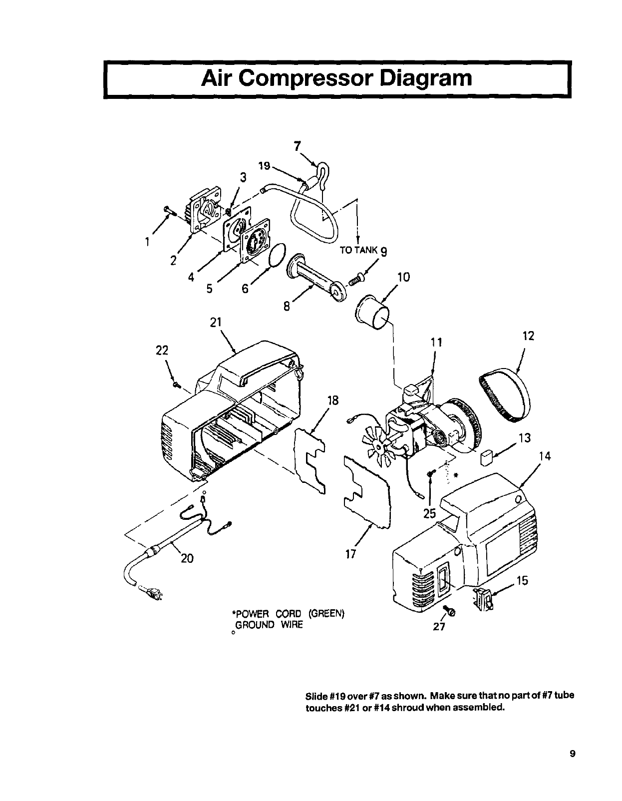
I Air Compressor Diagram I
1
2
45
7
6
TO TANK 9
21
/
10
18
17
*POWER CORD (GREEN)
GROUND WIRE
o
11
/
27
12
13
Y
15
14
Slide #19 over #7 as shown. Make sure that no part of #7 tube
touches #21 or #14 shroud when assembled.
9
I
KEY
NO.
/1
2
* 3
* 4
5
* 6
7
+ 8
/9
+ 10
11
12
* 13
14
15
* 16
>17
>18
19
20
21
/22
PART NUMBER
CAC-1196
CAC-4323
CAC-1289
CAC-4111
CAC-1342
DAC-163
DAC-168
SSS-16
CAC-1285
CAC-4322-1
DAC-162
DAC-167
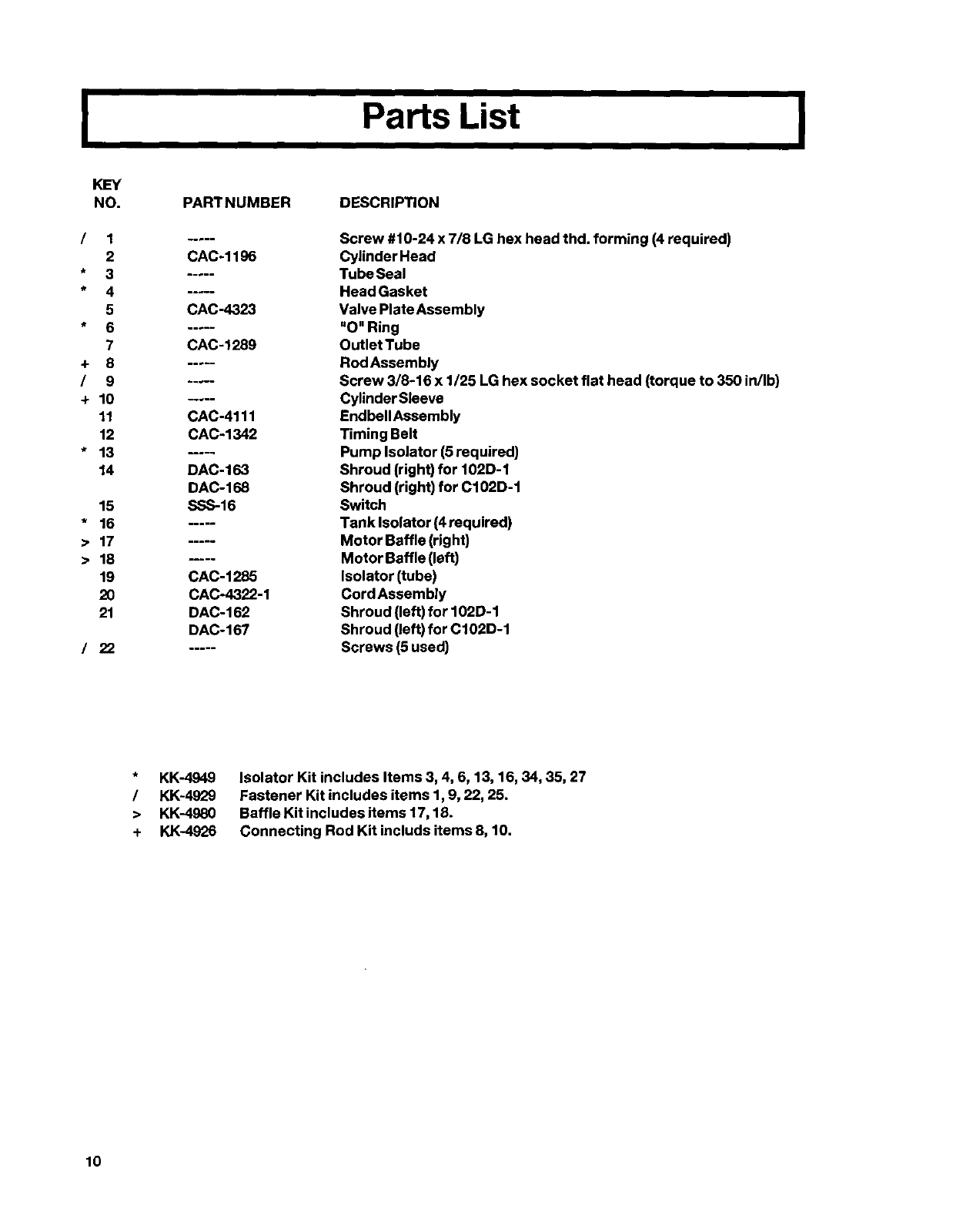
Parts List
DESCRIPTION
Screw #10-24 x 7/8 LG hex head thd. forming (4 required)
Cylinder Head
Tube Seal
Head Gasket
Valve PlateAssembly
"O" Ring
Outlet Tube
Rod Assembly
Screw 3/8-16 x 1/25 LG hex socket flat head (torque to 350 in/Ib)
Cylinder Sleeve
EndbellAssembly
Timing Belt
Pump Isolator (5 required)
Shroud (right) for 102D-1
Shroud (right) for C102D-1
Switch
Tank Isolator (4 required)
Motor Baffle (right)
Motor Baffle (left)
Isolator (tube)
CordAssembly
Shroud (left) for 102D-1
Shroud (left) for C102D-1
Screws (5 used)
I
/
>
+
KK-4949
KK-4929
KK-4980
KK-4926
Isolator Kit includes Items 3, 4, 6, 13, 16, 34, 35, 27
Fastener Kit includes items 1,9, 22, 25.
Baffle Kit includes items 17,18.
Connecting Rod Kit includs items 8, 10.
10
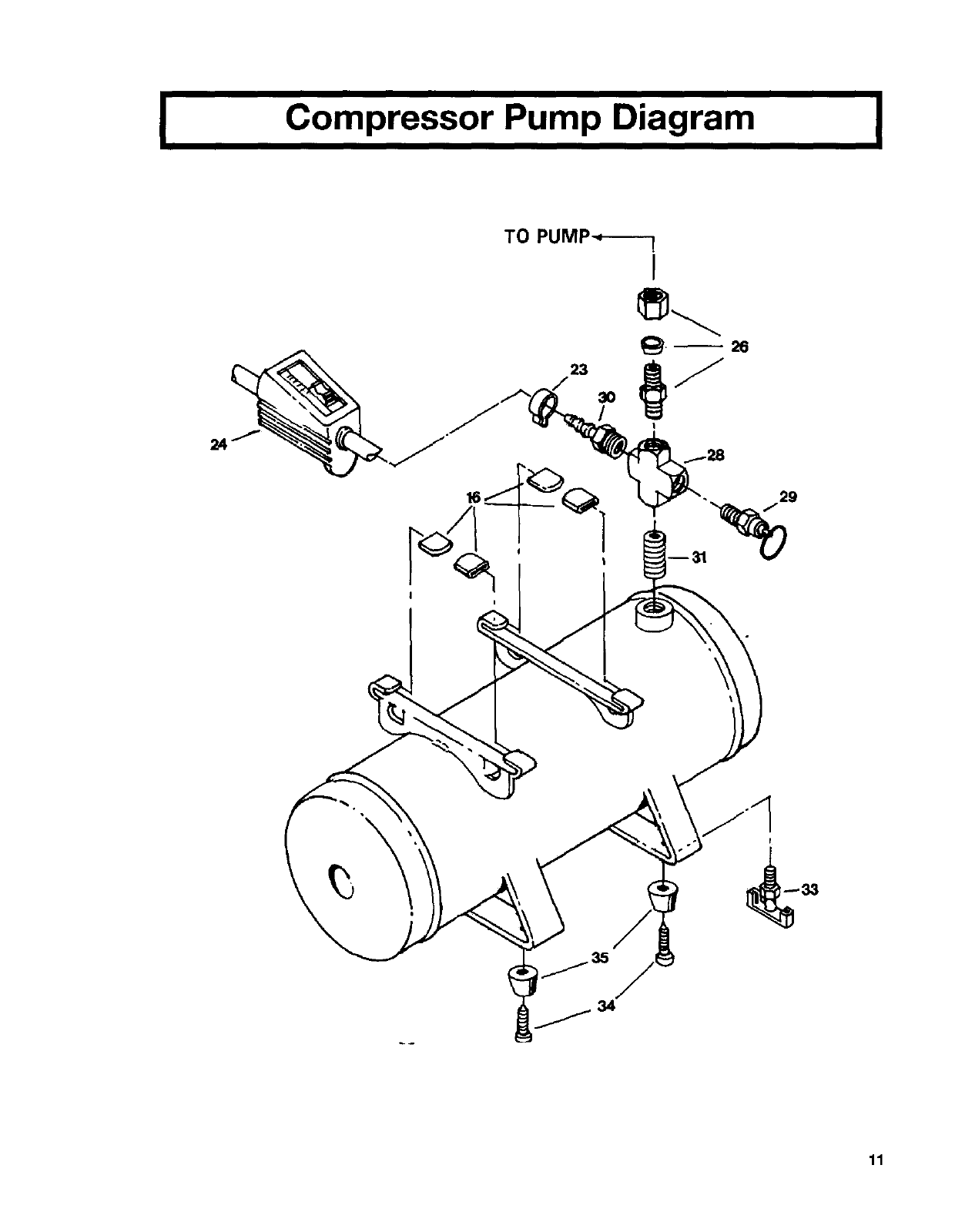
ICompressor Pump Diagram I
TO PUMP-,_---
I
t
\
11
I
KEY
NO. PARTNUMBER
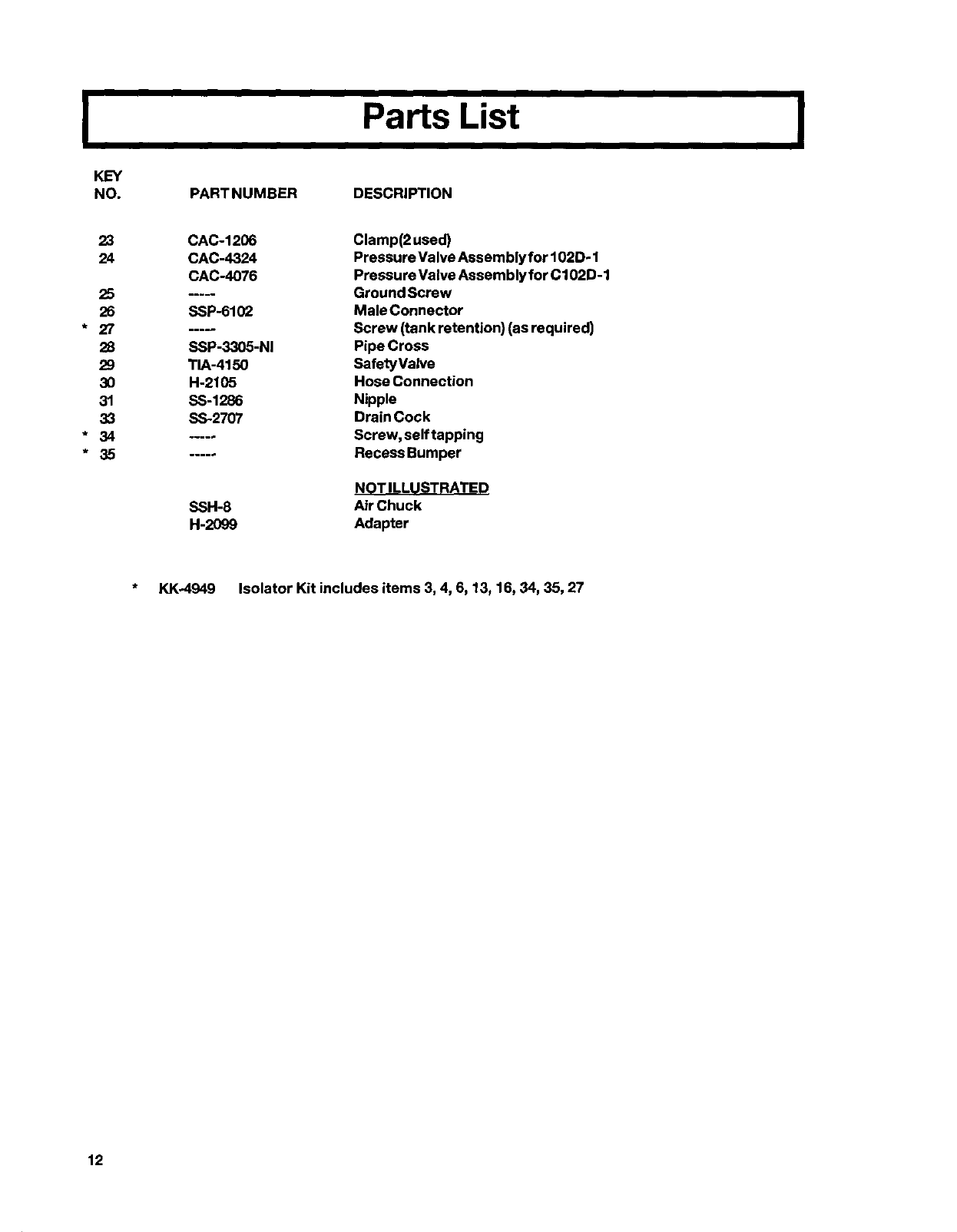
Parts List
DESCRIPTION
I
23
24
25
26
* 27
28
29
3O
31
33
* 34
* 35
CAC-1206
CAC-4324
CAC-4076
SSP-6102
SSP-3305-NI
TIA-4150
H-2105
SS-1286
SS-2707
Clamp(2 used)
Pressure Valve Assembly for 102D- 1
Pressure Valve Assembly for C102D-1
Ground Screw
Male Connector
Screw (tank retention) (as required)
Pipe Cross
SafetyValve
Hose Connection
Nipple
Drain Cock
Screw, self tapping
Recess Bumper
NOT ILLUSTRATED
SSH-8 Air Chuck
H-2099 Adapter
* KK_4949 Isolator Kit includes items 3, 4, 6, 13, 16, 34, 35, 27
12

IService Notes I
13

I Service Notes I
14

IService Notes I
15
OWNERS MANUAL FOR
PERMANENTLY
LUBRICATED
AIR COMPRESSOR
MODEL NOS,
102D-1
(For Home Use Only)
Attach Sales Receipt Here.
Retain Original Sales Receipt as
Proof of Purchase for Warranty
Repair Work.
WARRANTY
This product is covered by the
DeVilbiss one year limited
warranty (SP-100-C). The
warranty can be found in the
General Manual or is available
upon request.
An "Authorized Warranty Service Center Directory" is included with your
unit.
When ordering repair parts from your local Authorized Service Center,
always give the following information:
• Model number of your compressor
• Part number and description of the item
you wish to purchase
If you have any questions or need the location of the nearest Authorized
Service Center call our Customer Service Hotline (Toll Free) 1-800-888-
2468, Ext 2, Monday thru Friday 8:00 a.m. to 4:30 p.m. (CST) and talk with
our Trained Customer Service Representatives.
The Model number can be
found on the maintenance
label on the side of the tank.
Model
No.
The Date Code number can
be found on the foil label on
the air tank.
Date
Code
No.
The Manufactures
Number (ASME code
compressors only) is
located on the metal data
plate which is welded on
to the backside of the air
tank.
MFG
No.
DeVilbiss Air Power Company • 213 Industrial Drive •Jackson, TN 38301-9615
