DIAS Automotive Electronic Systems TS211 TPMS Sensor User Manual Product
DIAS Automotive Electronic Systems Co., Ltd. TPMS Sensor Product
Manual
1
TPMS
USER MANUAL
2
CONTENTS
1. INTRODUCTION OF TPMS...............................................................4
2. BILL OF TPMS ASSEMBLY ...............................................................4
3. TPMS PRODUCT SPECIFICATION ..................................................5
4. DISPLAY INTERFACE INTRODUCTION...........................................7
5. FUNCTION INTRODUCTION ............................................................8
5.1 NORMAL DISPLAY OF TEMPERATURE AND PRESSURE..............8
5.2 LOW PRESSURE ALARM .................................................................9
5.3 HIGH PRESSURE ALARM ................................................................9
5.4 FAST-LEAKING SETTING ...............................................................10
5.5 HIGH TEMPERATURE ALARM ....................................................... 11
5.6 SENSOR MALFUNCTION ALARM .................................................. 11
6. TYRE INTERCHANGE SETTING INTRODUCTION........................13
6.1 STANDARD TYRE PRESSURE SETTING ......................................13
6.2 TYRE INTERCHANGE SETTING ....................................................13
7. TECHNOLOGY PARAMETERS.......................................................15
7.1 TPMS DISPLAY ...............................................................................15
7.2 TPMS SENSOR...............................................................................15
8. ANNEX.............................................................................................16
3
Federal Communication Commission Interference Statement
This equipment has been tested and found to comply with the limits
for a Class B digital device, pursuant to Part 15 of the FCC Rules.
These limits are designed to provide reasonable protection against
harmful interference in a residential installation. This equipment
generates uses and can radiate radio frequency energy and, if not
installed and used in accordance with the instructions, may cause
harmful interference to radio communications. However, there is no
guarantee that interference will not occur in a particular installation. If
this equipment does cause harmful interference to radio or television
reception, which can be determined by turning the equipment off and
on, the user is encouraged to try to correct the interference by one of
the following measures:
- Reorient or relocate the receiving antenna.
- Increase the separation between the equipment and receiver.
- Connect the equipment into an outlet on a circuit different from that
to which the receiver is connected.
- Consult the dealer or an experienced radio/TV technician for help.
This device complies with Part 15 of the FCC Rules. Operation is
subject to the following two conditions: (1) This device may not
cause harmful interference, and (2) this device must accept any
interference received, including interference that may cause
undesired operation.
FCC Caution: Any changes or modifications not expressly approved
by the party responsible for compliance could void the user's
authority to operate this equipment.

4
1. INTRODUCTIONOFTPMS
TPMS is the shortened form of tyre pressure monitoring system.
TPMS is the active safety system of vehicle. It is used for real-time
monitoring tyre pressure and tyre temperature and transmitting the
information of tyre to driver timely and accurately. TPMS can reduce the
risk of tyre blowing and damaging resulted from low pressure, high
pressure, and high temperature and leaking. Thus protect effectively the
life and property of drivers and passengers.
TPMS display can be installed directly in air-conditioning vent in cab.
It can be also installed in other suitable position through mushroom
stick. The four sensors are installed inside tyre respectively.
When the vehicle starts and its speed is higher than 20km/h, the
sensors installed inside tyre can real time collect the tyre pressure, tyre
temperature and so on. Then the information is transmitted by radio to
TPMS display. TPMS display displays corresponding information after it
receives the wireless signal and alarms when the tyre is abnormal.
2. BILLOFTPMSASSEMBLY
Serial number name Amount Unit
1 Tyre pressure sensor 4 PCS
2 Tyre pressure monitoring display 1 PCS
3 Power supply wiring harness 1 PCS
4 Clip
1 PCS
5 Mushroom stick
1 PCS
5
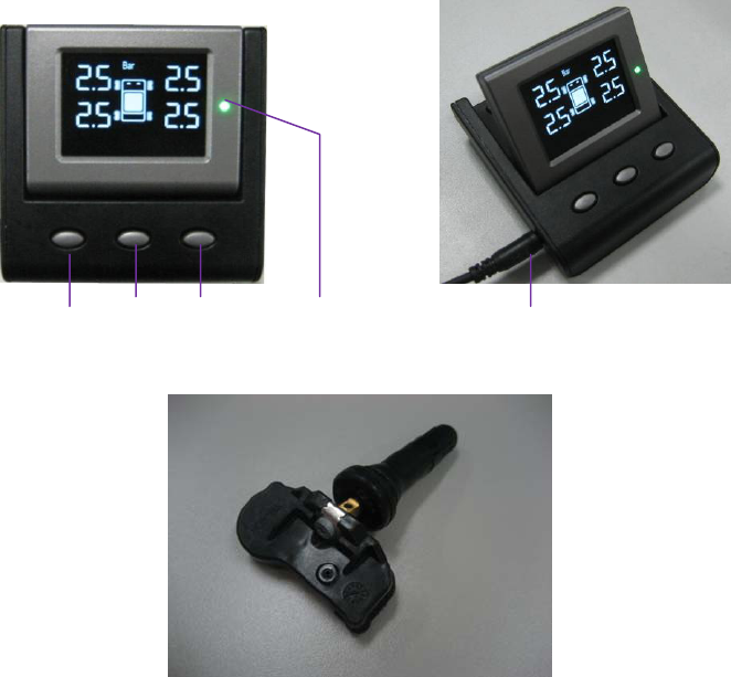
3. TPMSPRODUCTSPECIFICATION
SET T/P NEXT Indication Light Power Supply Interface
Fig 1 TPMS Display
Fig 2 TPMS Sensor
Indicator light introduction
① Green:State indication that shows the system is normal and
has no alarm information;
② Red:Alarm indication that shows alarm information exists in the
system.
6
Key introduction:
① “SET” is the key used for setting. The tyre interchange can be
done with this key. The particular operation is as the following
paragraph 6: Tyre Interchange Setting Specification.
② “T/P” is the key used for switching the display value of
temperature and pressure. Through pressing this key, the value
of tyre temperature and tyre pressure on the display can be
switched.
The tyre ID can be shown on the display after that “T/P” is
pressed for 4s. Then press “NEXT”, we can inquire the ID of
different tyre. The display of tyre ID can exit through pressing
“SET”.
③ “NEXT” is the key that after you press the key for 4s, TPMS
comes into matching mode. In this mode, the sensors can be
changed by users. Press “NEXT” again, the matching mode
can exit.
Warm Reminders:
When install the TPMS display, don’t install it above air-bag
without fail for fear of additional injury to drivers and passengers
when the air-bag opens under emergency conditions.
If you need to change the sensors, please go to designated 4S
shop or vehicle repair garage to do the matching using special
tool by career man.
If your hub is steel and you need to change the tyre, please
change tyre together with valve of tyre pressure sensor.
All the figures in the introduction are only the sketch map.
Please refer to the real object.
7
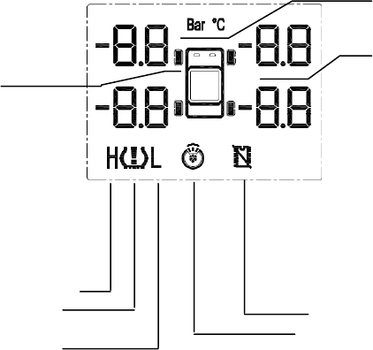
4. DISPLAYINTERFACEINTRODUCTION
TPMS display is electrified when the vehicle key is switched to “ON”.
The display shows the value of temperature and pressure recorded last
time as the following figure 3.
After the vehicle starts and its speed is higher than 20km/h, every
date shown in figure 3 updates real time to up to date status.
P/T units
P/T value
Tyre position
High P/T alarm indication
P/T alarm indication Malfunction alarm indication
Low pressure alarm indication Fast-leaking alarm indication
Annotate:
P—pressure, T—temperature. As to pressure unit: 1bar=105Pa(equal approximately
to 1 standard atmospheric pressure)
Fig3 TPMS display interface introduction
Warm Reminders:
Only upon the condition that the vehicle starts and the vehicle
speed is higher than 20km/h, every date shown on TPMS
display may updates real time to up to date status.
8
5. FUNCTIONINTRODUCTION
TPMS display can show corresponding indication or alarm
information according to different tyre status such as normal pressure,
low pressure, high pressure, high temperature, fast leaking and so on.
Each status is introduced in details below.
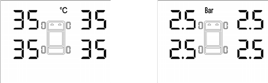
5.1 NORMAL DISPLAY OF TEMPERATURE AND PRESSURE
After the speed of vehicle is higher than 20km/h, TPMS display can
show normally the temperature and pressure value of every tyre as
shown in figure 4.
Temperature display Pressure display
Fig 4 Normal temperature/pressure display sketch map
Warm Reminders:
In this manual, the value of temperature and pressure shown in
display interface is schematic value. Tyre temperature and
pressure value of your vehicle will display real time according to
the specific actual conditions of your vehicle.
9
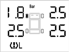
5.2 LOW PRESSURE ALARM
If the pressure of one or more tyre is lower than 75% of standard
tyre pressure after the speed of vehicle is more than 20km/h, TPMS can
alarm within 6s.
After TPMS sends alarm signal, the alarm sound lasts for 10 times
and the red alarm indication is lighted. In addition, TPMS display shows
the position of alarm tyre, pressure value and alarm indication.
The following figure 5 shows that the left front tyre pressure is low.
Fig 5 Low pressure alarm indication
The alarm sound can be stopped through pressing arbitrary key. But
the alarm indication light is still red. The indication light switches
automatically from red to green until the tyre pressure recovers normal.
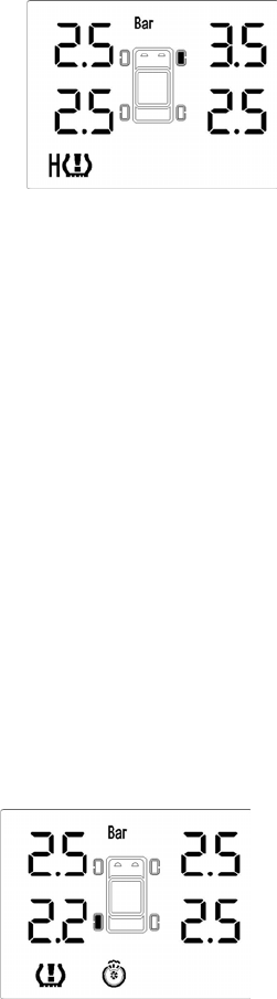
5.3 HIGH PRESSURE ALARM
If the pressure of one or more tyre is higher than 125% of standard
tyre pressure after the speed of vehicle is more than 20km/h, TPMS can
alarm within 6s.
After TPMS sends alarm signal, the alarm sound lasts for 10 times
and the red alarm indication is lighted. In addition, TPMS display shows
the position of alarm tyre, pressure value and alarm indication.
The following figure 6 shows that the right front tyre pressure is high.
10
Fig 6 High pressure alarm indication
The alarm sound can be stopped through pressing arbitrary key. But
the alarm indication light is still red. The indication light switches
automatically from red to green until the tyre pressure recovers normal.
5.4 FAST-LEAKING SETTING
If the leaking speed of one or more tyre is higher than 30kPa/min
after the speed of vehicle is more than 20km/h, TPMS can alarm within
48s and point out the position of leaking tyre.
If the leaking speed of one or more tyre is higher than 5kPa/s after
the speed of vehicle is more than 20km/h, TPMS can alarm within 8s.
After TPMS sends alarm signal, the alarm sound lasts for 10 times
and the red alarm indication is lighted. In addition, TPMS display shows
the position of alarm tyre, pressure value and alarm indication.
The following figure 7 shows that the left rear tyre is flat.
Fig 7 Fast-leaking alarm indication
The alarm sound can be stopped through pressing arbitrary key. But
11
the alarm indication light is still red. The indication light switches
automatically from red to green until the tyre pressure recovers normal.
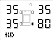
5.5 HIGH TEMPERATURE ALARM
If the temperature of one or more tyre is higher than 75℃ after the
speed of vehicle is more than 20km/h, TPMS can alarm within 30s and
point out the position of high temperature tyre.
After TPMS sends alarm signal, the alarm sound lasts for 10 times
and the red alarm indication is lighted. In addition, TPMS display shows
the position of alarm tyre, temperature value and alarm indication.
The following figure 8 shows that the right rear tyre temperature is
high.
Fig 8 High temperature alarm indication
The alarm sound can be stopped through pressing arbitrary key. But
the alarm indication light is still red. The indication light switches
automatically from red to green until the tyre temperature recovers
normal.
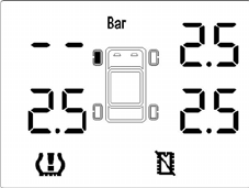
5.6 SENSOR MALFUNCTION ALARM
After the speed of vehicle is more than 20km/h, TPMS will send
alarm signal within 10min and point the position of malfunction tyre
pressure sensor if some sensor status don’t display because of sensor
malfunction, using up of battery capacity.
After TPMS sends alarm signal, the alarm sound lasts for 10 times
12
and the red alarm indication is lighted. In addition, TPMS display shows
the position of malfunction tyre and the malfunction alarm indication.
The following figure 9 shows that the left front tyre is malfunction
tyre.
Fig 9 Sensor malfunction alarm indication
The alarm sound can be stopped through pressing arbitrary key. But
the alarm indication light is still red. The indication light switches
automatically from red to green until the communication between TPMS
sensor and TPMS display recovers normal.
Warm Reminders:
For the sake of safety of yourself and your car, please stop the
car quickly to make the check. Go to 4S shop or professional
repair garage to do a careful examination at your convenience
so as to avoid the malfunction thoroughly.
The information of sensor can be lost under bad weather or
intense electromagnetic interference conditions.
13
6. TYREINTERCHANGESETTINGINTRODUCTION
6.1 STANDARD TYRE PRESSURE SETTING
Standard tyre pressure default value of this TPMS is 2.5Bar. The
standard tyre pressure may be different for different concrete vehicle
type. Users should set the standard tyre pressure according to specific
vehicle type. The setting of standard tyre pressure needs to use special
matching tool. Users can go to specified 4S shop or vehicle repair
garage to do the settings.
6.2 TYRE INTERCHANGE SETTING
The purpose of tyre Interchange setting is to interchange left, right,
front, rear tyre. This function facilitated the regular service to tyre.
In order to avoid wrong operation, the setting methods and steps of
TPMS to enter tyre interchange mode is as follows:
① Press “SET” without releasing. Then press “NEXT”. The two
buttons is pressed together for 4s or more, then releases;
② Press “SET” again, the tyre interchange mode can exit.
The tyre needed to change can be selected through pressing “T/P”
for several times according to the change of tyre position in the
display.
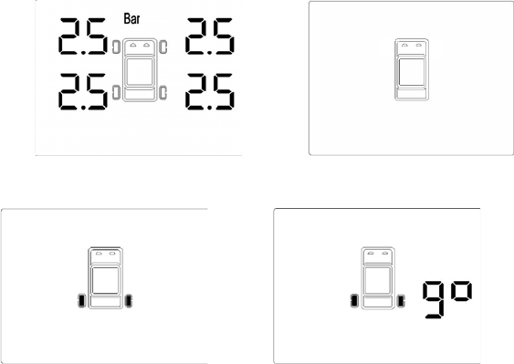
For example: if the position of left rear tyre and right rear tyre
position needs to change, the operation steps is as follows:
① Starting status as shown in figure 10;
② The tyre interchange setting mode enters according to operation
steps mentioned above as shown in figure 11;
③ The left rear tyre and right rear tyre is changed through pressing
“T/P” for several times according to the change of tyre position
in the display as shown in figure 12;
14
④ Then press “SET” to make sure that the two tyres will
interchange as shown in figure 13;
⑤ Finally press “SET” again, the tyre interchange is done. Then
the display interface returns to starting status as shown in figure
10.
Fig 10 Fig 11
Fig 12 Fig 13
Warm Reminders:
① As for tyre interchange, please operate without fail according to
above steps. Otherwise the false operation may happen. This
can lead to wrong sensor installation position. Accordingly lead
to the data inaccurateness or malfunction alarm.
② After the tyre interchange, please go to specified 4S shop or
vehicle repair garage to make the inspection using special tool
to make sure that there is no mistake in changing.
15
7. TECHNOLOGYPARAMETERS
7.1 TPMS DISPLAY
Operating temperature: -20℃~+70℃
Storage temperature: -40℃~+95℃
Modulation format: FSK
Communication frequency: 433.92MHz
Receiving sensitivity: -105dBm
Operating voltage: DC12V±3V
7.2 TPMS SENSOR
Operating temperature: -40℃~+105℃
Storage temperature: -40℃~+125℃
Pressure measurement range: 0~4.5Bar
Pressure measurement accuracy: ±0.1Bar
Modulation format: FSK
Communication frequency: 433.92MHz
Emission frequency: 1dBm

16
8. ANNEX
Annex 1:Guarantee card main couplet
Please tear this page along broken line when purchasing and this page
is reserved by supplier.
Name Type
Vehicle
license
number
E-mail
User
datum
Telephone Address
Type Number
Product
records Sensor ID
Supplier Vendition
date
Vendition
records Telephone Address
Installation
company Address
Installation
records Installation
person Installation
date

17
Annex 2:Guarantee card assistant couplet
Please fill out this couplet completely at the time of purchase and this
couplet is preserved by users.
Type Number
Left
front Right
front
Product
leaving
factory
records Sensor ID Left
rear Right
rear
Supplier Telephone
Purchase
records Address
Installation
company Installation
person
Installation
records Installation
address

18
Annex 3:Maintenance record card
Date Malfunction
description
Maintenance
company
Maintenance
person
User
signature

19
Annex 4:Tyre transposition record card
Transposition time Transposition tyre Operator