DIXELL S r l XJ20010000 Transceiver unit User Manual Dixell
DIXELL S.r.l. Transceiver unit Dixell
Contents
- 1. Users Manual
- 2. User Manual
User Manual
1592010320 XJ200 GB r1 3 24 10 2014-FCC XJ200 1 / 3
XJ200
1. GENERAL WARNING
1.1 TO BE READ BEFORE USING THIS MANUAL.
This manual forms an integral part of the product and must be kept near the device
for easy and quick consultation.
The device must not be used for purposes different than those described below and
particularly, it cannot be used as a safety device.
Verify the limits of application before proceeding.
1.2 SAFETY PRECAUTIONS
Verify that the connections comply with the instructions in this manual before
connecting the device.
Do not expose the unit to water or humidity: use the device only within the
stipulated working limits, avoiding sudden changes in temperature and high
atmospheric humidity in order to prevent condensation from forming.
Caution: disconnect the electrical connections of the device before any
maintenance.
The module must never be opened.
If the device is faulty or malfunctions, return it to the retailer or to "DIXELL s.r.l."
(refer to address) with a precise description of the fault.
2. GENERAL DESCRIPTION
The wireless communication modules of the XJ200 range are a radio communication
system for Dixell monitoring systems.
The iCOOLL range consists of the XJ200 radio module and its power supplier PW-200J.
XJ200 can cover a variety of functions within the monitoring network:
a. Master: when it is connected to the X-WEB monitoring system.
b. Slave/Repeater: when it is connected to the subnets of devices equipped
with RS485.
c. Repeater: when it is assigned the function as a simple bridge towards other
subnets that cannot be reached directly by the master.
The XJ200 modules enable 2-way communication between Dixell devices/modules
equipped with an RS485 output that are appropriately connected to each other and the
monitoring unit of the X-WEB ranges, thereby replacing the connection via an RS485
cable.
Up to 200 devices can be connected to the same XJ200 (communication between the
module and the devices is via RS485), thereby covering several workstations with the
same communication module.
The maximum distance possible between the XJ200 modules in an open space (with no
obstacles) is 200 metres. This distance can be remarkably reduced in the presence of
interference such as radio emitters, generators of electrical or magnetic fields that can
affect the proper communication between the XJ200 modules.
The range of serial addresses allowed on the instruments connected to the iCOOLL
modules is from 1 to 244.
N.B. In order to work with the iCOOLL modules, the instruments must be equipped with
an RS485 serial port and use ModBUS-RTU communication protocol.
3. FRONT PANEL
LED: the module has a few LED signals
POWER Green - Flashing with a frequency of 1 Hz: the module is ON and running
RS485 Yellow - Data is being transmitted/received via RS485 by the module
RADIO Green -The module is transmitting via radio
4. INSTALLATION AND ASSEMBLY
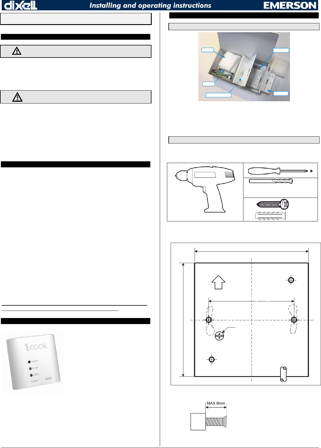
4.1 PACKAGE CONTENTS
3. Bracket
4. Manual
1. Xj200
Sponge
2. Screws
Each XJ200 package contains the following components:
1. XJ200 radio device
2. 2 self-tapping screws 3.9x6.5T to fix the XJ200 to the fixing bracket
3. Wall fixing bracket
4. Instructions manual
4.2 TOOLS TO FIX THE XJ200
4.2.1 DIRECT FIXING TO THE WALL
Parts required for assembly (not supplied)
Ø 5 mm
2 x M5
2 x Ø 5 mm
1. To fix the module directly to the wall, use the cut out below to make the 2 holes
“B” at the distance indicated in fig. 1.
TOP
Ø MAX 6mm (0.2”)
80.00mm (3.15”)
80.00mm (3.15”)
60.00mm (2.36”)
CABLE
A
A
B B
Fig. 1
2.
Insert the dowels and fix the screws with
a maximum distance of 8 mm from the
head to the wall
3. Fix the XJ200 to the head of the screws by rotating the container appropriately
1592010320 XJ200 GB r1 3 24 10 2014-FCC XJ200 2 / 3
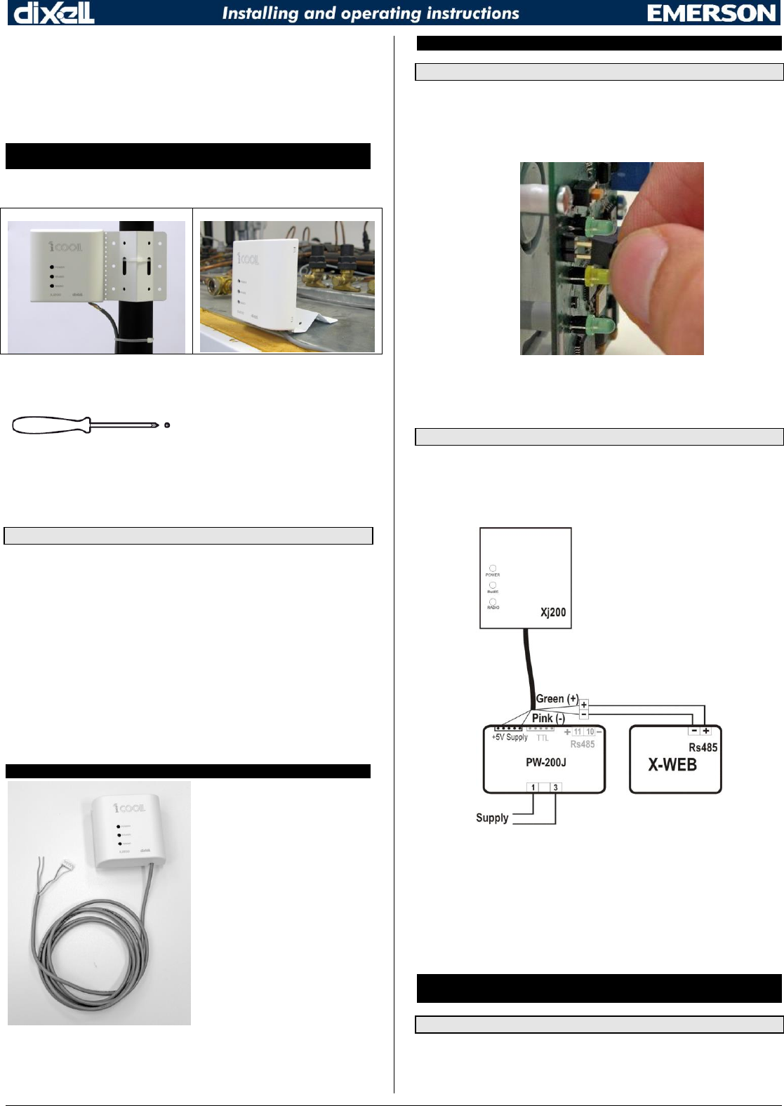
4.2.2 FIXING WITH THE USE OF A BRACKET
A suitable fastening bracket is included in every package to be used to:
a. shelves mount fitting;
b. pipemount fitting with appropriate retaining clamps (not supplied)
c. wall mount fittin
as shown in the following pictures:
!!!!!ATTENTION!!!!!
Set the XJ200 in the desired place in a VERTICAL POSITION.
Avoid horizontal or slanting positions.
RIGHT FIXING MODE
RIGHT FIXING MODE
Parts required for assembly (not supplied)
1. Fix the XJ200 to the fixing bracket using the 2 screws in the package
2. The 2 screws are to be entered in holes “A” as shown in Fig. 1.
3. The bracket can be bent and fixed so that the XJ200 is installed in a vertical
position.
4.3 RECOMMENDATIONS FOR PROPER INSTALLATION
If possible, place the module high up in order to guarantee enhanced data
transmission/reception.
If possible, avoid intermediate obstacles such as barriers, walls, floors and
counters between the modules.
If necessary, pass through the obstacle using the cable and install the module on
the opposite side in order to have it in direct view with the master module
connected to the X-WEB.
The maximum distance possible between the XJ200 modules in an open space
(with no obstacles) is 200 metres.
If the installation spans over a number of floors, try to position all the modules on
the same floor and connect the devices via cable in order to prevent
communication problems due to obstacles caused by the floor/ceiling.
The allowed temperature range for correct functioning is between 0 and 60 °C.
Avoid places subject to heavy vibrations, corrosive gas, excessive filth or
humidity.
5. CONNECTIONS
Each module is supplied complete with
a 1.5-metre cable to connect the serial
communication line and the power line.
The XJ200 is powered by the PW-200J
power supplier and therefore, it is
connected to the RS485 serial line. The
following types of connection are
possible.
6. X-WEB - XJ200 MASTER CONNECTION
6.1 TRANSFORM THE XJ200 TO MASTER
The XJ200 connected to the X-WEB must be configured as Master.
To do so:
a. Remove the cover of the XJ200.
b. Close the jumper found inside the XJ200 by inserting the micro switch as
shown in the picture below.
c. Close the cover of the XJ200 once again.
d. Connect the XJ200, PW200J and the X-WEB as shown in the connection
diagram below.
6.2 XJ200 –X-WEB CONNECTION
XJ200 and PW-200J connection
a. Disconnect the power supply from the PW200J
b. Connect the GREEN wire to the RS485 “+” terminal of the PW-200J
c. Connect the PINK wire to the RS485 “-” terminal of the PW-200J
d. Connect the white connector to the "+5V supply" connector of the PW-200J
XJ200 and X-WEB connection
Use the disconnecting terminal supplied with the PW-200J as a bridge of the RS485
line.
The connection between the XJ200 and X-WEB is then implemented as follows:
Connect the GREEN wire of the XJ200 to the RS485 “+” terminal of the X-WEB
Connect the PINK wire of the XJ200 to the RS485 “-” terminal of the X-WEB
Power the X-WEB and the PW200J once again.
7. XJ200 CONNECTION AND DEVICES EQUIPPED WITH A SERIAL
OUTPUT
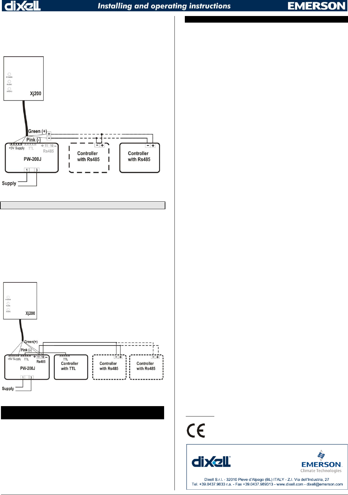
7.1 DEVICE EQUIPPED WITH AN RS485 SERIAL OUTPUT
7.1.1 Device with an RS485 output but not able to power the
XJ200.
E.G. Ranges: XR100C; XR500C; XR75CX and XR77CX.
XJ200 and PW-200J connection
1592010320 XJ200 GB r1 3 24 10 2014-FCC XJ200 3 / 3
Connect the white connector to the "+5V supply" connector of the PW-200J.
Connect the other devices to the RS485 serial line in compliance with the polarity.
Use the disconnecting terminal supplied with the PW-200J as a bridge of the RS485 line
with the XJ200 as follows:
Connect the GREEN wire of the XJ200 to the RS485 “+” terminal.
Connect the PINK wire of the XJ200 to the RS485 “-” terminal.
7.2 DEVICE EQUIPPED WITH A TTL SERIAL OUTPUT
7.2.1 Device with a TTL output but not able to power the XJ200.
E.G. Ranges: Prime CX, Wing Basic New, XC400C and XC600C
XJ200 and PW-200J connection
Connect the GREEN wire to the RS485 “+” terminal of the PW-200J.
Connect the PINK wire to the RS485 “-” terminal of the PW-200J.
Connect the white connector to the "+5V supply" connector of the PW-200J.
Controller connection with TTL and PW-200J
Connect the other devices to the RS485 serial line in compliance with the polarity.
Connect the 2 TTL outputs of the PW200J and the device.
Then connect the RS485 line to the PW200J, in compliance with the polarity.
8. CHECK OF GOOD CONNECTION QUALITY BETWEEN THE XJ200
MASTER AND THE OTHER XJ200 OF THE NETWORK
The following must be implemented in order to verify good connection quality between
an XJ200 and the master connected to the X-WEB:
1. Connect and power the XJ200 Master to the X-WEB
2. Set the XJ200 in place where it is to be installed
3. Power the XJ200 and press the LED Power button for a couple of seconds
4. A test cycle begins and lasts a few minutes
5. At the end of the cycle, the following remains on:
a. Good communication: the GREEN “RADIO” LED is on
b. Insufficient communication: the YELLOW “RS485” LED is on; in this case,
try installing the XJ200 in a better position or connect another XJ200
between the Master and the XJ200 being tested.
9. TECHNICAL DATA
Operating Frequency:
Europe version: XJ200 -00000: 869.4 - 869.650 MHz
AUS and USA version: XJ200 -10000: 906 - 924 MHz multi channel (*)
(*) the channel selection must be done through one of the DIXELL approved
tools.
Container: Self-extinguishing ABS
Format: Front panel 80 x 80 mm; depth 5 mm
Power Supply:
XJ200 +5Vdc (from the controller or from the PW-200J module)
Note: the PW200J feeder or any Dixell controllers that can power the XJ200 are SELV-
type. Max Power <18VA, DC current < 8A.
Power Consumption: 0.30 VA max.
Operating Temperature: from 0 to 60 °C
Storage Temperature: -25 to 60
Relative Humidity: 20 - 85% (no condensation)
The XJ200 -00000 is compliant with the following standards:
ETSI EN 300 220-2 V2.1.2 (2007-06)
ETSI EN 301 489-3 V1.4.1 (2002-08)
CEI EN 60950-1 (2007-02)
It therefore meets the essential requirements of the following Directives:
Radio and telecommunications terminal equipment 99/5/EC
Electromagnetic compatibility 2004/108/EC
Low Voltage equipment 2006/95/EC
The XJ200 -10000 (906 - 924 MHz) is compliant with the following standards:
AS/NZS 4268: 2008:
Classification: Schedule 1: Item 45
FCC 15.247
The XJ200 -10000 (906 - 924 MHz) is compliant to Part 15 of the FCC Rules:
Operation is subject to the following two conditions:
(1) this device may not cause harmful interference, and
(2) this device must accept any interference received, including interference that may
cause undesired operation.”
Unauthorized repairs, changes or modifications could result in permanent damage to the
equipment and void your warranty and your authority to operate this device under Part
15 of the FCC Rules.
NOTE: This equipment has been tested and found to comply with the limits for a Class A
digital device, pursuant to part 15 of the FCC Rules. These limits are designed to
provide reasonable protection against harmful interference when the equipment is
operated in a commercial environment. This equipment generates, uses, and can
radiate radio frequency energy and, if not installed and used in accordance with the
instruction manual, may cause harmful interference to radio communications. Operation
of this equipment in a residential area is likely to cause harmful interference in which
case the user will be required to correct the interference at his own expense.
The XJ200 -10000 (906 - 924 MHz) is compliant to RSS 102
Cet XJ200 -10000 (906 - 924 MHz) instrument répond aux normes RSS 102
This device complies with Industry Canada RSS-210. Operation is subject to the
following two conditions: (1) this device may not cause interference, and (2) this device
must accept any interference, including interference that may cause undesired operation
of the device.
Le présent appareil est conforme aux CNR d’Industrie Canada applicables aux appareils
radio RSS-210. L’exploitation est autorisée aux deux conditions suivantes : (1) l’appareil
ne doit pas produire de brouillage, et (2) l’utilisateur de l’appareil doit accepter tout
brouillage radioélectrique subi, même si le brouillage est susceptible d’en compromettre
le fonctionnement.
The complete Declaration of Conformity can be found at:
www.dixell.com