DME 406-ELT Survival Rescue Beacon, Raft Mounted User Manual 320417
DME Corporation Survival Rescue Beacon, Raft Mounted 320417
DME >
Users Manual

Document No. Y1-06-0130 Rev. B
6830 N.W. 16th Terrace, Fort Lauderdale, FL 33309
(
954
)
975-2100 *Fax
(
954
)
979-3313 * www.dmecor
p
.com
OPERATION MANUAL
for the
MODEL SRB-406 TYPE S ELT
PN P3-03-0041 Series
Where used: P3-03-0041 Series
Next assembly: P3-03-0041 Series
Y1-06-0130
Prepared by: Don Van Erem Date: September 12, 2002
Checked by: Eric Hiner Date: September 12, 2002
Approved by: Eric Hiner Date: September 12, 2002
Approved by: Phil Pelfrey Date: September 12, 2002
NOTICE IS HEREBY GIVEN THAT ALL DATA CONTAINED IN, REVEALED BY, OR SHOWN IN THIS DOCUMENT ARE PROPRIETARY AND
BELONGS TO DME CORP., FT. LAUDERDALE, FLORIDA. IT IS FURNISHED AND RECEIVED IN CONFIDENCE SOLELY FOR
INFORMATIONAL PURPOSES OF THE RECIPIENT FOR THE PURPOSES HEREWITH TRANSMITTED. NONE OF THE INFORMATION
CONTAINED HEREIN SHALL BE USED FOR ANY OTHER PURPOSES OR DUPLICATED IN WHOLE OR IN PART WITHOUT PRIOR
AUTHORIZATION OF DME CORP.

Y1-06-0130 Rev. B
Page 2 of 9
REVISIONS
Revision Date Change Description Approval
A 12/19/02 ECO #13565 T. Cohen
B 3/21/03 ECO #13724 T. Cohen
Y1-06-0130 Rev. B
Page 3 of 9
1.0 GENERAL DESCRIPTION
The Model SRB-406 Emergency Locator Transmitter (ELT) is a survival-type transmitter
manufactured for use on aviation life rafts. The ELT broadcasts on 121.5 MHz, 243.0
MHz, and 406.028 MHz.
The SRB-406 is designed for semi-permanent installation in survival raft or raft devices.
It features automatic activation when it comes in contact with water and also
incorporates a manual activation means for operation on land. There are two models,
the -001 and the -002. The -001 single antenna SRB-406 is configured for use on
non-reversible, self-righting rafts and the -002 dual antenna SRB-406 is for rafts that are
reversible.
2.0 COMPONENT DESCRIPTION AND OPERATION
2.1 Transmitter
The transmitter produces a signal for search and rescue when locating survivors of an
aircraft accident. The transmitter is automatically activated when the raft is deployed in
water. The transmitter may also be manually activated. In the event that the raft is
deployed on land, the ELT may be activated manually by touching both of the contacts
on the antenna base with moistened fingers. ELT activation is indicated by the flashing
light emitting diode (LED) located on the top of the transmitter case.
The SRB transmitter is protected inside a tough sealed plastic case. The case is
designed to protect the transmitter electronics and battery from external loads
encountered in packing the inflatable device.
To prevent inadvertent activation in the packed raft, the transmitter features an arming
pin and lanyard. The transmitter does not receive battery power until the arming pin is
pulled from the transmitter case. The arming pin lanyard is attached on the raft so that
the arming pin is pulled automatically upon inflation of the raft system. Once the arming
pin is pulled, the unit will begin to transmit as soon as the water activation
sensor/antenna(s) is submerged (or the sensors are shorted by means of moistened
fingers). Reinstalling the arming pin into the mating clip will cause the unit to cease
transmitting.

Y1-06-0130 Rev. B
Page 4 of 9
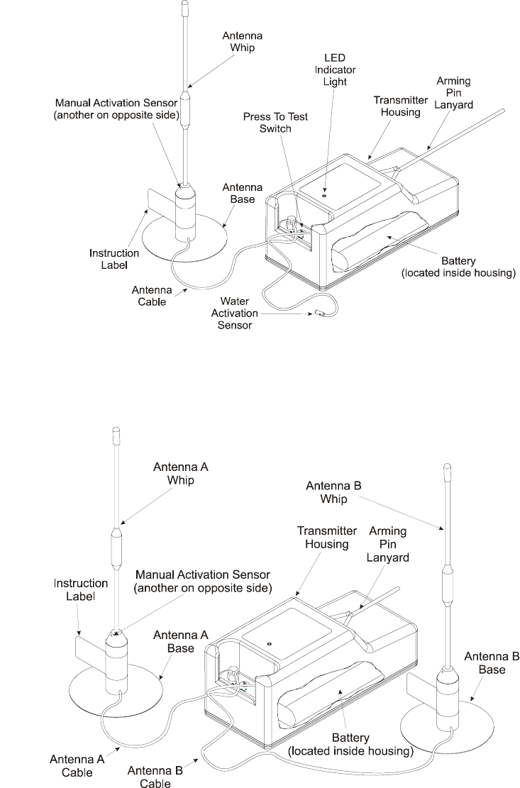
-001 Single Antenna Model
-002 Double Antenna Model
Figure 1. Model SRB-406
I
Bilin
g
ual
Bilingual
Y1-06-0130 Rev. B
Page 5 of 9
2.2 Arming Pin
The arming pin requires a pull force of approximately 8 pounds from an angle of 0 to 60
degrees from the pin axis. The manufacturer of the inflatable device performs
attachment of the lanyard to the raft.
To activate the transmitter, pull the lanyard until the cylindrical arming pin is removed
from the corresponding clip in the transmitter housing. As soon as the arming pin is
removed, the unit is ready to transmit. In the case of the -001 single antenna model, to
begin transmitting, the antenna sensors must be submerged (or moistened fingers
placed across both sensors of the antenna) or the water activation sensor must detect
water. With the -002 double antenna model, transmission will begin when the antenna
sensors are submerged (or moistened fingers are placed across both sensors of one of
the antennas).
Inserting the arming pin back into the clip in the transmitter housing will either disallow
operation or cause an operational unit to cease transmitting. Transmission has stopped
when the LED on the transmitter housing ceases flashing.
2.3 Antenna
The antenna(s) is an omni-directional, vertically polarized, whip antenna. The antenna
assembly consists of a pliant rubber base and a replaceable flexible whip antenna
mounted in a base. The antenna is resonant at 121.5 MHz, 243.0 MHz and 406.028
MHz.
The rubber antenna base features activation sensors that operate by water contact or
other low resistance contact. The base also incorporates a RF ground plane, which
enhances RF transmission when in contact with the raft surface.
2.4 Water Activation Sensor
On the -001 model, a second wire lead from the transmitter case terminates in a low
resistance water activation sensor. This wire lead is generally mounted so that following
normal inflation of the raft, the water activation sensor will be located well below the
water line. This sensor lead is detachable from the transmitter.
On the -002 model, the water activation sensors are on both antennas.
2.5 Battery
Power for the SRB-406 transmitter is provided by a single lithium battery pack that is
located within the transmitter housing. The battery pack uses 4 each
lithium/manganese dioxide, 1-1/4 “C” size cells. The cells are arranged in series. Each
cell is protected from short circuit by a manufacturers installed safety device (PTC).
Y1-06-0130 Rev. B
Page 6 of 9
The maximum storage temperature range for the battery pack is –200C to +400C. The
maximum installation temperature range is -550C to +850C. At temperatures above
910C the battery pack is subject to venting.
Battery Pack General Precautions
• Temperatures near the melting point of the lithium metal (1800C) will result in a
lithium fire and rupture of the cells.
• The battery pack (with or without item packaging) must be protected from
compressive loads. Do not stack heavy objects or other battery packs on each
other without mechanical protection.
• The battery pack must be protected from the formation of condensation and
exposure to water or other fluids.
• Refurbishment and reconditioning of the battery pack is forbidden and may result in
a fire or explosion.
• The battery pack must not be short-circuited. Short-circuiting for more than one
minute is detrimental to the battery pack and may cause overheating of the cells.
• Do not charge this battery pack. This is not a rechargeable battery pack.
• Store the battery pack in its original packaging until ready for installation in the ELT.
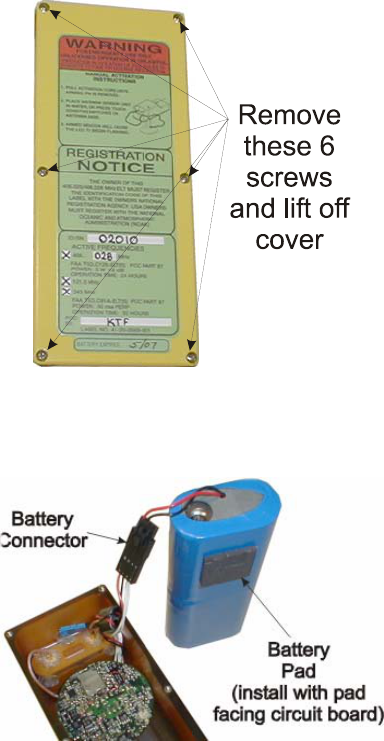
To replace the battery, see Figures 2 and 3 and proceed as follows:
1. Remove the 6 phillips screws from the bottom side of the unit.
2. Lift out the battery.
3. Depress the latch on the battery connector cable and slide the connector apart;
properly dispose of the old battery.
4. Slide the new battery connector into the corresponding connector half from the
SRB-406 until it snaps into place.
5. Place the new battery into the cavity in the unit, push battery cabling into cavity
sufficiently to facilitate installation of the cover removed in step 1; ensure the
battery does not pinch any of the wires.
6. Place cover removed in step 1 over unit, align cover attachment holes in cover
with corresponding holes in unit, and install the 6 screws removed in step 1.
Torque screws to achieve a compressed gasket height of approximately .020
inches (free gasket height is .060 inches and approximate torque is 3 ± 0.5 inch
pounds).

Y1-06-0130 Rev. B
Page 7 of 9
Figure 2. Cover Removal
Figure 3. Battery Removal/Installation
2.6 Press to Test Switch
A tactile-type switch, labeled PRESS TO TEST, is provided on the transmitter housing
(see Figure 1 for location) for the purpose of testing the unit for proper operation.
Momentarily depressing the PRESS TO TEST Switch will cause the LED to flash once
immediately. Then, after approximately 10 seconds, the LED will produce either 2 or 3
flashes followed by approximately 15 seconds of off time, and then flash again. This
flashing sequence will continue for approximately 30 to 45 seconds and then cease.
NOTE: Two flashes indicate that the unit is operating properly. Three flashes indicate
that a problem exists; in this case, the unit should be returned to a repair station.

Y1-06-0130 Rev. B
Page 8 of 9
2.7 Distress Message
The Model SRB-406 ELT transmits a radio signal on 406.028 MHz to satellites of the
Cospas Sarsat network. This radio signal contains a short format digital message that is
unique to each beacon and includes beacon information (manufacturer information,
serial number and beacon type) and user/country code information.
It is the buyer's responsibility to provide user and country code information and to
register the beacon with the appropriate agency of the country under which the user will
operate the aircraft.
The beacon is programmed by DME Corporation during its manufacture. DME
Corporation can reprogram the beacon if any user/country code information changes.
3.0 TECHNICAL DATA
3.1 Buoyancy
The SRB-406 is used only as part of a TSO-C69 or TSO-C69A raft, or a TSO C12c life
raft. The transmitter/battery assembly is secured in a pouch that is an integral part of the
raft, therefore, buoyancy of the SRB-406 is not required.
3.2 Tags and Labels
The transmitter case and battery case each have visible identifying labels that provide
the part number, model number, FCC identification number, FAA TSO number, and
additional data.
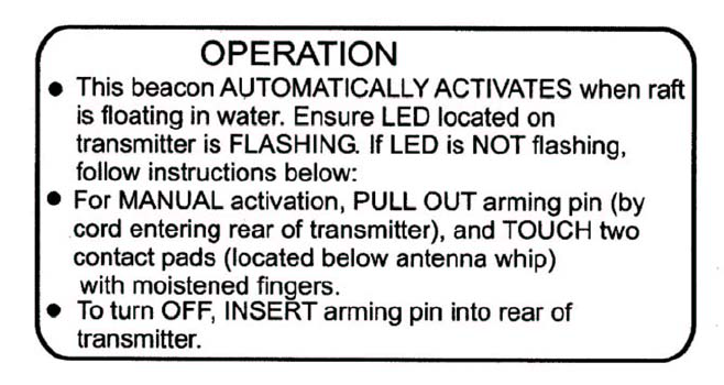
An instruction tag is attached to the antenna base, providing essential operating
instructions to life raft occupants. See Figure 4.
Figure 4. Instruction Tag Attached to Antenna Base (English Version)
Y1-06-0130 Rev. B
Page 9 of 9
3.3 Operating Specifications
Transmitter Duty Cycle: 5 watt digital signal every 50 seconds, for 440
millisecond duration
Homing Signal Tone Frequency: 700 Hz Sweep between 1600 and 300 Hz
Homing Signal Tone Sweeping Rate: 2 to 4 times per second
Operating Temperature Range: -20`C to 55`C (-4°F to 131 °F)
Homing Signal Operating Range: 100-280 miles (160-450 km), subject to atmospheric
conditions, receiver altitude, and sensitivity
Battery Operating Life: 50 hours (homing)
Battery Operating Life: 24 hours (406 MHz)
Battery Service Life: 5.0 years (service)
Volume Envelope: 22 cubic inches (360 cubic cm)
Weight: Single Antenna - 24 oz. (680 grams)
Double Antenna - 27 oz. (765 grams)
Antenna: Flexible, Omnidirectional, Vertically Polarized, Field
Replaceable, Whip
Frequency: 121.5 MHz, 243.0 MHz, 406.028 MHz