DMP ELECTRONICS AVL Auto Vehicle Locator (AVL) User Manual TechGuide AVL 1e3m7C
DMP ELECTRONICS INC. Auto Vehicle Locator (AVL) TechGuide AVL 1e3m7C
Contents
- 1. Users Manual Part I
- 2. Users Manual Part II
Users Manual Part I
Technical Guide
AVL75
Auto Vehicle Locator System
www.avl.tw
A
A
V
V
L
L

i
Copyright
COPYRIGHT © 2005-2006 DMP ELECTRONICS INC. for AVL75 SYSTEM.
DMP ELECTRONICS INC. is hereby also refer to as “DMP” during the course of this documentary
literature. The information in this manual is subject to change without notice in pursue for
continuous improvement of the subject product and commodity. All rights reserved. The
manufacturer assumes no responsibility for any inaccuracies that may be contained in this document.
And makes no commitment to update or to keep current information contained in this manual.
Unauthorized use for whatever purposes are prohibited.
No part of AVL75 SYSTEM material may be reproduced, copied, translated or transmitted, in whole or
in part, in any form or by any means, by persons, organizations or corporations other than the AVL75
SYSTEM (its affiliates, divisions and units) without the prior written permission from DMP.
Trademarks Acknowledgement
is the registered trademark of DMP.
The Trademarks appearing on any AVL75 SYSTEM are the property of DMP and other third parties.
Nothing contained on the AVL75 SYSTEM literature should be construed as granting any license or
right to use any Trademark without the prior written permission of the owner of the Trademark.
Trademarks, logos, and services marks are collectively refer to as "Trademarks" in this section.
Microsoft, Windows and the Windows CE Logo are registered trademarks of Microsoft
Corporation in the United States and/or other countries.
Other brand names, or product names appearing in this literature are the sole properties and
registered trademarks of their respective owners. All names mentioned herewith serves as
identification purpose only.
is the identification mark for AVL75 SYSTEM of which the ownership is
reserved by DMP.
Owner’s Record
The serial number of this commodity is located at the bottom chassis of your AVL75 SYSTEM. Refer
to the model and serial number when you contact your nearest dealer or DMP offices for services. The
Model No. of this product is also indicated on the product label of your gift box as:
AVL750/751/752/753MWB (NWB/NXB/NXX/MWB/MXB/MXX/ … etc). Please check the description
of your model no. in Chapter 2.
A
A
V
V
L
L

ii
Special Notice to Users
DMP provides no warranty with regard to this manual, the software, or other information contained
herein and hereby expressly disclaims any implied warranties of merchantability or fitness for any
particular purpose with regard to this manual, the software, or such other information. In no event
shall DMP be liable for any incidental, consequential, or special damages, whether based on tort,
contract, or otherwise, arising out of or in connection with this manual, the software, or other
information contained herein or the use thereof.
DMP reserves the right to make any modification to this manual or the information contained herein
at any time without notice. The software described herein is governed by the terms of a separated
user license agreement or label sticker.
This product contains software owned by DMP and licensed by third parties. Use of such software is
subject to the terms and conditions of license agreements enclosed with this product. Software
specifications are subject to change without notice and may not necessarily be identical to current
retail versions.
Updates and additions to software may require an additional charge. Subscription to online service
providers may require a fee and credit card information. Financial services may require prior
arrangements with participating financial institution.
Safety Information
WARNING
Do not expose your AVL75 SYSTEM to the rain or moisture, in order to prevent shock and
fire hazard.
Never install your AVL75 SYSTEM in wet locations.
Do not attempt to open the cabinet of your AVL system to avoid electrical shock. Refer
to your nearest dealer for qualified personnel servicing.
Never touch un-insulated terminals or wire of your AVL75 SYSTEM unless your vehicle
engine is turned off.
In the service laboratory:
Never touch un-insulated terminals, unless the power adaptor and the display monitor
are disconnected.
Locate your AVL75 SYSTEM as close as possible to the electrical socket outline for easy
access, while avoiding force caused by entangling of your arms with surrounding cables
from the system.
Avoid using or installing the modem to the serial port of your AVL SYSTEM during a
storm or a lightning.
Do not use the telephone to report a gas leak in the vicinity of your AVL75 SYSTEM still
working. Turn off the system immediately.
USB connectors are not supplied with Limited Power Sources.
DO NOT ATTEMPT TO OPEN OR TO DISASSEMBLE THE CHASSIS
(ENCASING) OF THIS COMMODITY. PLEASE CONTACT YOUR
NEAREST DEALER FOR SERVICING FROM A QUALIFIED TECHNICIAN.

iii
Regulatory
FCC Class A Note
This equipment has been tested and found to comply with the limits for a Class A
digital device, pursuant to Part 15 of the FCC Rules. These limits are designed to
provide reasonable protection against harmful interference when the equipment is
operated in a commercial environment. This equipment generates, uses and can
radiate radio frequency energy and, if not installed and used in accordance with
the instruction manual, may cause harmful interference in which case the user will
be required to correct the interference at his own expense. Testing was done with
shielded cables. Therefore, in order to comply with the FCC regulations, you
must use shielded cables with your installation.
WARNING
This product Complies with EN55022 Class A. In a domestic environment this product may cause
radio interference in which case the user may be required to take adequate measures.
Changes or modifications to this unit not expressly approved by the party responsible for compliance
could void the user’s authority to operate the equipment.
This device complies with Part 15 of the FCC rules. Operation is subject to the following two
conditions: (1) this device may not cause harmful interference, and (2) this device must accept any
interference received, including interference that may cause undesired operation.
This digital apparatus does not exceed the Class A limits for radio noise emissions from digital
apparatus as set out in the interference - causing equipment standard entitled “Digital Apparatus”,
ICES-003 of the Department of Communications.
Cet appareil numérique respecte les limites de bruits radioélectriques applicables aux appareils
numériques de Classe (A) prescrites dans la norme sur le matériel brouilleur: “Appareils
Numériques”,NMB-003 édietée par le miniistre des Communications.
Manufacturer’s Declaration of Conformity
This equipment has been tested and found to comply with the requirements of
European Community Council Directives 89/336/EEC and 73/23/EEC relating to
electromagnetic compatibility and product safety respectively.
Underwriters Laboratories Inc. (UL)
Underwriters Laboratories Inc. (“UL”) has not tested the performance or reliability
of the Global Positioning System (“GPS”) hardware, operating software or other
aspects of this product. UL has only tested for fire, shock or casualty hazards as
outlined in UL's Standard, UL60950-1, 1st. Edition, Information Technology
Equipment – Safety – Part 1: General Requirements. UL Certification does not
cover the performance or reliability of the GPS hardware and GPS
operating software. UL MAKES NO REPRESENTATIONS, WARRANTIES
OR CERTIFICATIONS WHATSOEVER REGARDING THE PERFORMANCE OR
RELIABILITY OF ANY GPS RELATED FUNCTIONS OF THIS PRODUCT.
iv
Purchase Agreement Version 1.1
Purpose
In accordance to the general commercial conduct of Trust and Fair Trade, herewith below
is the agreement for the protection for both parties, DMP and Users in pursuant of trading.
Product Description
With this product, herewith also known as AVL75, which is a simplified & an economical design of an
embedded computer for Automotive Computing. The basic specification of this product comprises of
the latest x86 technology design, which runs at a speed of 166MHz, with onboard 128MB System
memory, 512KB SRAM, GPS, GSM/GPRS, WIFI LAN, OBD-II, Display, Audio, USB, and serial port
Interfaces.
Distribution Convention
1. This Product includes a Gift box, an inner case, AVL PC system, , User’s Manual, Utilities
& Drivers CD, and cable package (for cable definition, please refer to chapter 1, section
1.1 – Unpacking your AVL75). Upon receiving this product, kindly please refer to the
User’ Manual to check for the contents and appearance of this product; contact
immediately your nearest dealer or DMP office for any defective or missing parts. The
supplier will not be responsible for any reported discrepancy thereafter the expiration
period of 3-days from the date of purchase.
2. In consideration of transportation and the cost of storage, the supplier provides to the
distribution channel, a warranty of 13-months (12-months is granted to the end-user).
This warranty covers the failure caused by hardware breakdown, but does not cover the
act of misuse and mishandling.
3. The supplier will not accept unknown post, therefore if you wish to repair or to return
your goods – kindly please contact your nearest dealer to make your declaration, and
at the same time, apply for a RMA number (RMA stands for Return Merchandise
Authorization – please see the RMA form and fill-up for authorization).
4. The freight for Return goods for repair will follow the International customary practice
and convention: Both parties is to pay for freight of one shipment each. The shipper is
required to prepaid the freight from the place of origin (This means that the Returnee
(user) covers the freight for return goods, while the Supplier covers the freight for goods
after the repair).
5. Obsolete warranty is referred to as: (1)Expiration of warranty or (2)Damage due to
misuse within warranty. The Supplier will be taken into consideration of the
circumstances, to provide repair service with charges expense for obsolete warranty.
This expense includes the cost of material plus labor.
Note
If there is other particular issue not listed in the above conditions, both parties agreed to
follow the General Law of Commerce with fair and reasonable discussion in handling and
resolving any occurrence of argument.

v
TABLE OF CONTENTS
Copyright ……………………………………………………………….... i
Trademarks Acknowledgement ………….……………..….... i
Owner’s Record ………….………………………………………..….... i
Special Notice to Users ……………………………..………….... ii
Safety Information ………………………………….…………….... ii
Regulatory ……………………………………………………………….... iii
Purchase Agreement …………………………………………………….... iv
Chapter Subject Description Page No.
1 Introduction …………..……………………………………….. 1
1.1. Unpacking your AVL75 …………………………………..……. 1
1.2. Ordering Information …………………………………..……. 3
2 Function Description ….……………………………………. 4
3 Hardware Specification …………………………………... 5
3.1. System Block Diagram …………………………………..…… 6
4 Connectors Description ………………………………….. 7
4.1. Connectors Summary …………………………………………. 7
4.2. OBD-II Connector ……………………………………………….. 8
5 Application ………………………………..…………………….… 10
5.1. Application Scope Description ………………..…………. 10
5.2. Vehicle monitoring & security ………..………………….. 10
6 Hardware Overview …..……………………..………….… 11
6.1. LED Description ………..……………………………..……….. 11
6.2. LED Operation ………..……………………………..………….. 12
6.3. External Connector Summary ………..………………….. 13
7 General Hardware Specification ……...………….… 14
7.1. About AVL System ………..……………………………...…… 14
8 SIM Card Installation ..……………………………..….… 15
8.1. Steps for SIM card installation ……….……………...…… 15

vi
8.2. Reverse procedure for replacing SIM card ……..…… 17
9 Software support ……………………………………..….… 18
9.1. Summarizing the AVL software …………………...….… 18
9.2. Database and Data transmission server …..….…… 18
9.3 Backstage control management program …….…… 18
9.4 AVL Client software part ………………………………..…… 18
9.5 Principle of operation …………………………………….…… 19
9.6 System software overview …………………………….…… 19
10 Protocol & Drivers …………………………..………….…. 20
10.1. SRAM Drivers …………………………………………..…….…… 20
10.2. Using GPIO on AVL …….…………………………..…….…… 21
10.3. AVL Power Management Command Set ……………. 25
10.4. AVL Power Management Programming Reference ….… 35
11 AVL Communication Boards ……………..……….…. 38
11.1. Uncovering your AVL75 …………….…………………….…… 39
11.2. Removing your GPRS Modem card ………………….…… 41
11.3. Removing your OBD-II card Drivers …………….….…… 44
Appendix Subject Description Page No.
A Rear Connectors Pin Assignment Summary ... 46
C AVL Power Management …………………………….... 53
D SIM Card Holder ………………………………………….... 54
Limited Warranty …………………………………………………….... 55
Return Policy ………….……………………………………………….... 56
(c) Copyright DMP Electronics Inc. 2005. All rights reserved.

1
Chapter 1
1. Introduction
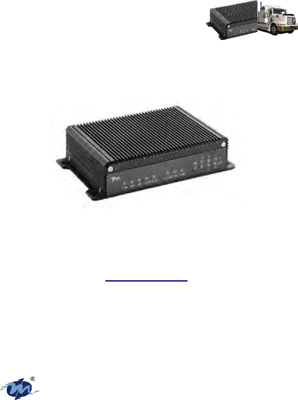
Auto Vehicle Locator System is popularly known as AVL (Auto stands for Automatic). The AVL75
(Auto Vehicle Locator System) is a highly integration of 4-in-1 hardware unit which consists of the
following hardware component:
Embedded Vortex86 computer/computing system
4-band GPRS communication module or any other type of communication Module.
24 GPS Global Satellite Positioning Receiver devices
5-in-1 Automobile/Vehicle/Car OBD2 real-time diagnosis system.
The term AVL is also known as Automatic, or Automated Vehicle Locator. Mostly Auto is a short cut
term for Automatic.
Aside from the above features , the Windows WINCE is the primary core and principal open source
control software.
At present, this type of AVL is widely used in the vehicle transporting market; hence ‘twas the most
advanced vehicle carrying locator (and also it is known as the automobile black box). Also the AVL
will be the best sharp weapon for future supervisor monitoring and management of the business
transporting and public vehicles enterprising.
1.1. Unpacking your AVL75
AVL75 system has been tested through a series of function test and quality audit before being
shipped out from the factory. To ensure that your AVL75 system is QC certified product, we have
included an AVL75 test program for your verification.
1.1.1 Packaging Contents
The contents of your AVL75 Package include:
1 AVL75 system x1 unit
2 AVL75 Technical Guide x1 booklet
3 AVL75 Driver & Utility CD x1 unit
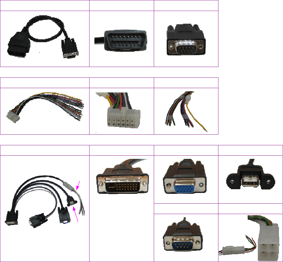
4 Cable package x1 unit
• CABLE-AVL-OBDII x1 pce.
• CABLE-AVL-DVI x1 pce.
• CABLE-AVL-PWR x1 pce.
1.2 Cable Package
DM&P Part Number CABLE Description Dimension in Length
CABLE-AVL-OBDII OBD2 Cable, RS232C(Female)-to-SAE J1962
connector(Male) 57.5mm(L)
CABLE-AVL-DVI DVI Cable, DVI(Male)-to-VGA/RS232/USB/
Special power cable (+12V/+3.3V) 40.5mm(L)
CABLE-AVL-PWR DC with Fuse socket power cable 23.5mm(L)
2
• CABLE-AVL-OBDII
Photo of CABLE-AVL-OBDII From (CAB-A1) To (CAB-A2)
• CABLE-AVL-PWR
Photo of CABLE-AVL-PWR From (CAB-B1) To (CAB-B2)
• CABLE-AVL-DVI
Photo of CABLE-AVL-DVI From (CAB-C1) To (CAB-C2) To (CAB-C4)
To (CAB-C3) To (CAB-C5)
CAB-A1 CAB-A2
CAB-B1 CAB-B2
CAB-C5
CAB-C4
CAB-C1 CAB-C2 CAB-C3

3
1.2. Ordering Information
TABLE 1.1 : Basic Standard Products
AVL750NXX Auto Vehicle Locator / Vortex86-166 with 128MB
SDRAM/32MB DOM/GPS/GPRS
AVL751NXX Auto Vehicle Locator / Vortex86-166 with 128MB
SDRAM/64MB DOM/GPS/GPRS
AVL752NXX Auto Vehicle Locator / Vortex86-166 with 128MB
SDRAM/128MB DOM/GPS/GPRS
AVL753NXX Auto Vehicle Locator / Vortex86-166 with 128MB
SDRAM/256MB DOM/GPS/GPRS
AVL754NXX Auto Vehicle Locator / Vortex86-166 with 128MB
SDRAM/512MB DOM/GPS/GPRS
TABLE 1.2 : Software and Test Kit
AVL750TEST AVL75 series Test Proof Evaluation Kit (Include hardware +
software + MS WinCE License)
AVL750BSP WinCE5.0 BSP
TABLE 1.3 : Optional Modules
AVLDOM-64 DMP DOM 64MB
AVLDOM-128 DMP DOM 128MB
AVLDOM-256 DMP DOM 256MB
AVLDOM-512 DMP DOM 512MB
TABLE 1.4 : Product Selection Table
DOM Memory
capacity BASIC
(GPS+GPRS) BASIC +OBD-II
32MB AVL750N AVL750NB
64MB AVL751N AVL751NB
128MB AVL752N AVL752NB
256MB AVL753N AVL753NB
512MB AVL754N AVL754NB

4
Chapter 2
2. Function Description
1. Automatic supervision monitoring of the automobile engine start-up – if the engine starts, the
AVL will then automatically starts the inbound control system to make the surveillance and the
record movement. The AVL here is referred to as AVL75.
2. After the automobile engine stops, the AVL turns off the control system. The length of time for
the machine or system to be turn-off is software adjustable. This is to prevent short stops
phenomenon and abnormal unloading/loading of cargo.
3. May record the Vehicle GPS utilizing the global satellite positioning information, the recording
precision is highly accurate up to one second at a time.
4. In our Memory design using Flash + NVSRAM, this helps extend the life of the Flash registers for
recording, surpassing the life usage of over 10 years.
5. The GPRS communication Module has 4-band frequencies 850/900/1800/1900 MHz supporting
the TCP/IP communication protocol, enabling the monitoring program platform for easy
application development.
6. Complete integrity supporting J1850PWM /J1850VPWM/ KWP2000/ KWP1281/ ISO9141-2 (with
the exclusion of CAN BUS?), a total of 5 kinds of OBD-II for immediate real-time automobile
diagnosis hardware interface that provide breakdown diagnosis code.
7. May establish wake-up time setting or remote control awakening supervisory monitoring,
enabling to keep track of the vehicle position at any time.
8. It constitutes with the construction of 4 groups of belts onboard, with light partner isolation for
the input of the specific/specified monitor contact, this is utilize to detect the compartment or
the vehicle door when it opens.
9. It constructs another 4 groups of belts onboard, with light partner isolation for the output of the
specific control in contact, this output may be utilize to provide reports to the police.
10. Provides connection to outside communication, using a group of external standard RS232
interface, enabling the manual installation for the expansion of these devices.
11. Provides lamp indication for status condition on PWR/SAVE/GPS/GPRS/OBD2/SLEEP LED.
12. Supports the input source range from DC 8V ~ DC 36V, suits different types of big and small
vehicles.
13. Provides connection to outside storage, using external USB device for storage of transmission
medium, or using the GPRS communication transmission, or the downloading of updated
software.
14. Provides connection to DVI port monitor, or extended LVDS interface to LCD monitor, for the
demonstration and display of electronic map and DVD broadcast.
15. Operating temperature range is from -30 to +70oC

5
Chapter 3
3. Hardware Specification
Vortex86-166/166MHz SOC
System memory SDRAM 128MB
SRAM 512KB for data backup
IDE interface for DOM / EmbedDisk (Factory default standard 32MB).
BIOS 256KB
External USB x2
Internal USB x1
LPC-MIO W83697UF
AC97 CODEC ALC202A
Power Management Control chip with I2C interface
DC power input 12V/24V Auto Detect
Photo Isolate input x4 with LED display
Photo Isolate output x4 with LED display
COM1 D type 9-pin RS232
COM2 OBD-II / Option D type 9-pin RS232
COM3 GPRS module MC55/56 or SIM200 or other CDMA
COM4 GPS module GN80-V
GPIO Port 2,3,4,8
VGA, LVDS LCD display output
LED display status
XPCI expand connector
Power Voltage detect.
Wake on Timer
Wake on Photo Isolate input x4
Wake on GPRS(Ring, Voice, GPRS data, Modem, SMS)
System Auto Power on by detect input volt
Manual push button power on/off
Software control power off.
GPRS module SIM card easy changeable.
Power consumption: +12V @ 600mA
Operating temperature range is from -30 to +70oC
Volume Size Dimension 140mm X 98mm X 36mm
6
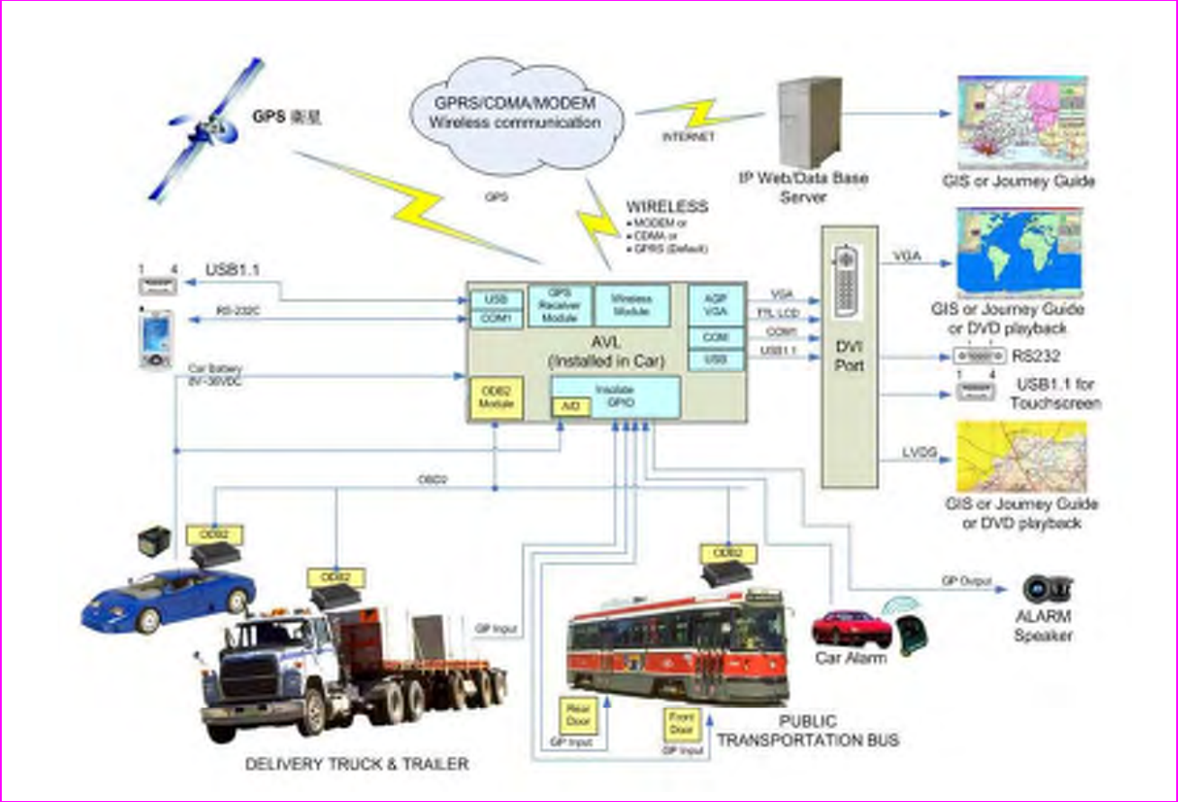
3.1. System Block diagram

7
Chapter 4
4. Connectors Description:
4.1. Connectors Summary
DC Power input: 14PIN(7x2)-4.20mm (0.165”) Wafer Dual Row connector x1
(Include Photo Isolate INx4, OUTx4,Temperature sensor input x1)
COM2 OBD-II Connector DSUB-9 Male or COM2 RS232 DSUB-9 Female
USB 90 degree connector x1
COM1 RS232 DSUB-9 Female or DVI 29pin connector x1
(DVI connector include VGA, LVDS LCD,USBx1,RS232(TX/RX)
Power on/off Switch Pushbutton x1
GPRS Antenna SMA type x1 (Female)
GPS Antenna SMA type x1 (Female)
Internal GPRS Module interface connector x1
Interface OBD-II Module interface connector x1
Internal IDE interface for DOM x1
Internal GPIO 16Bits expand connector.(Option) x1
Note: For pin assignment information, please refer to the Appendices section.
8
4.2. OBD-II Connector
OBD-II was introduced in the United States on January 1, 1996, all cars and light trucks built and sold
were required to be OBD II equipped (models built in late 1995 then on were OBD-II compliant).
There are two factors to identify if your vehicle is definitely OBD II equipped:
1) There will be an OBD II connector as shown in Figure 1A below, and
2) There will be a sticker note or nameplate under the hood indicating: "OBD II compliant".
4.2.1. The Physical Connector
FIGURE 4.1 : SAE J1962 connector
4.2.2. The Connector Outline
TABLE 4.1 OBD-II Pin Assignment
Pin Assignment
Pin 2 - J1850 Bus+
Pin 4 - Chassis Ground
Pin 5 - Signal Ground
Pin 6 - CAN High (J-2284)
Pin 7 - ISO 9141-2 K Line
Pin 10 - J1850 Bus
Pin 14 - CAN Low (J-2284)
Pin 15 - ISO 9141-2 L Line
Pin 16 - Battery Power
FIGURE 4.2 : OBD-II Connector
4.2.3. The Connector Pin Defined
FIGURE 1C. shows the pin assignment used in
compliant with OBD-II specification.
FIGURE 4.3 : OBD-II Connector Pin Defined
FIGURE 1. SAE J1962 connector provides
access to the diagnostic network

9
4.2.4. Location of OBD-II connector
Look for your OBD-II under the dash and behind ashtrays. The OBD-II connector must be located
within three feet (0.914 meter) of the driver, and must not require any tools to be revealed.
4.2.5. Communications Protocol
The protocol used in vehicle varies for different manufacturers – the GM cars and light trucks use SAE
J1850 VPW (Variable Pulse Width Modulation), while Fords use SAE J1850 PWM (Pulse Width
Modulation). Chrysler products, all European and most Asian imports use ISO 9141 circuitry.
There are some variations among captive imports such as the Cadillac Catera, a German Opel
derivative, which uses the European ISO 9141 protocol.
On 1996 and later vehicles, you can tell which protocol is used by examining the OBD II connector:
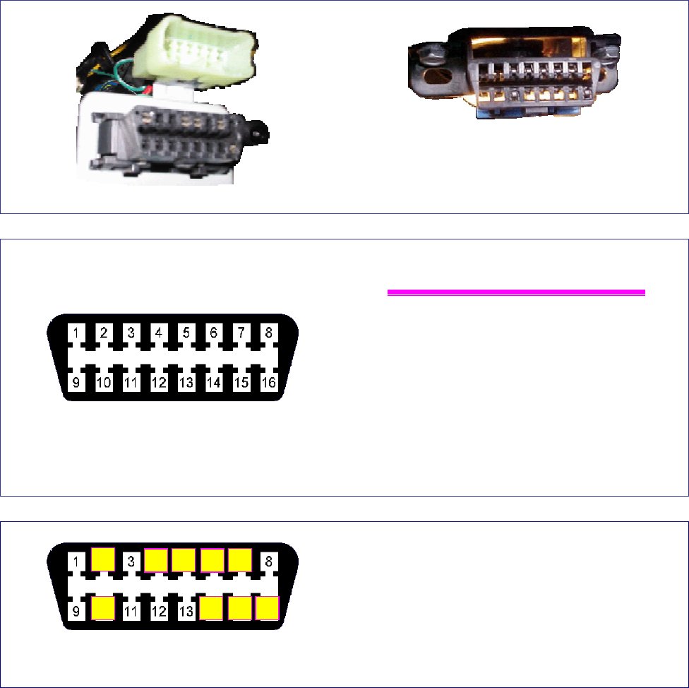
TABLE 4.2 OBD-II Types Summary
SAE J1850 VPW GM GM cars and li
g
ht trucks: The connector
should have metallic contacts in pins 2, 4,
5, and 16, but not 10.
SAE J1850 PWM Ford
T
he connector should have metallic contacts
in pins 2, 4, 5, 10, and 16.
ISO 9141-2 Chrysler, all European and most
Asian imports
T
he connector should have metallic contacts
in pins 4, 5, 7, 15, and 16.
ISO 9141 protocol Cadillac and Opel Others like Cadillac Catera and German
Opel have some variations with the
connector pin assignment.
KWP2000 Similar to ISO 9141 protocol
Daewoo, Hyundai, KIA, Subaru STi, and
some Mercedes. Dual K-Line that supports
bi-directional and unidirectional L-Line
signal
KWP1281
Similar to ISO 9141 protocol with the
exception of support for ABS and
year 2002+ engines/ transmissions/
airbags
Same as above. Dual K-Line that supports
bi-directional and unidirectional L-Line
signal
CAN CAN is widely used in European
vehicles and North American
manufacturers. By strategy, newer
GM vehicles is entirely based on the
CAN protocol: GMLAN. Like J1939,
OBD-II, J1587 & LIN: GMLAN is a
higher level protocol (HLP) that is
implemented on top of the hardware
in software either on the host or the
device hardware itself (firmware).
2004 and newer Ford, Ja
g
uar, Mazda,
Mercedes, Nissan, and Toyota. GMLAN:
CAN operates at speeds up to 1 Megabit -
this is 100 times faster than a J1850 VPW
network.
Note: All the above mentioned article served for the purpose of sharing information as references. The above
contents are the sole copyright of the respective owner and organization.
If your vehicle has this style connector, but doesn't have these pins populated, you probably have a
pre-OBD-II vehicle. Adding to some other confusion, even having the connector with the contacts
shown above is not a guarantee of OBD II compliance. This style connector has been seen on some
pre-1996 vehicles which were not OBD II compliant.

10
Chapter 5
5. Application
5.1 Application Scope
The AVL75 is highly integrated hardware device that provides communication and automation, which
is built on the embedded WinCE O/S software, enabling the users to make the necessary modification,
while achieving different industrial application.
AVL75 is equipped with the following external connectors – the GSM antenna connector, the GPS
antenna connector, WIFI antenna connector, the RS232C connector, the power connector, and an
internal SIM card holder connector.
Attaching the GSM/GPRS antennas, it would provide communication for vehicle security and
monitoring. Whilst the RS232C connector is used for the interaction with personal computer (or
with notebook) – for the configuration to the business enterprise in providing a stand-alone tracking
operation mode. In some cases, GPS data collecting and the Map representation for user
application can be done without GSM network.
5.2 Vehicle Security & Monitoring
The security monitoring plays an important role for AVL. Most AVL suppliers integrate security
connector with external sensors, like shock-sensor and microwave-sensor. Suppliers provide
interfaces with a central lock of a vehicle, with a parking vehicle’s lights, with the system of ignition’s
blockage and with the siren.
Such security interface may include control activities like:
A. Inputs
o Sensor input (different ranges)
o Opened/closed doors
o Ignition wire
B. Outputs
o External 433 MHZ RF Antenna
o Ignition blockage
o Siren output
o Central Lock (close and open the doors),
o Automotive Parking Lights
o External LED
o 12V power wires.
AVL75 can work independently without security control and other add-on components/parts. It
needs no changing of the software, just remove the additional modules from the AVL unit.
11
Chapter 6
6. Hardware Overview
The AVL Unit is a device, designed for Vehicle’s Tracking and Guarding that transfers data from this
device to the designated or assigned WEB server and transfer back using GPRS terminal for SMS
(Short Message Service) or TCP/IP data transferring. Also the SMS messaging is organized in the
stand-alone operation mode, i.e. data transferring toward and back to the user’s mobile phone.
The AVL75 unit is organized on the principle of modular expandability.
A principal basic base module (Vortex86 CPU board) of the AVL75 represents a computer system,
with other related communication and tracking module in the designated option electronic add-on
modules..
Table 6. AVL75 Parts and Modules
Model No. PCB Board no. Description
AVL-1 DM38 Auto Vehicle Locator (COM1/DVI Option)
AVL-2 DM39 AVL MC2 MC55/56 GPRS Modem Module
AVL-3 DM40 AVL SIM200 GPRS Modem Module
AVL-5 DM42 AVL OBD-II Module / XH78 EOBD/OBD-II
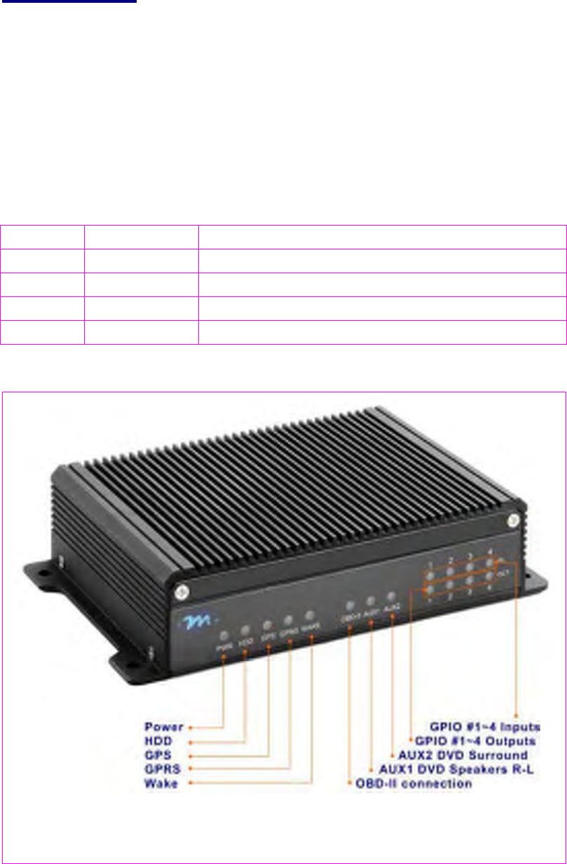
6.1. LED DESCRIPTION
FIGURE 6.1 : Front panel LEDs overview

12
The AVL unit is equipped with sixteen (16) LEDs, showing status of the unit during its period of
functioning.
TABLE 7. LED FUNCTION DESCRIPTION
Name Description LED color and status Name Description LED color and status
D24 Power Orange, Fixed D29 OBD-II Green, Lit-On, Fixed
D25 HDD Yellow, Blinking D30 AUX1 Green, Fixed
(user defined)
D26 GPS Green, Blinking D31 AUX2 Green, Fixed
(user defined)
D27 GPRS Green, Blinking LED1~LED4 IN Green, Double-layer,
GPIO Input, Blinking
D28 WAKE Green, Blinking,
Wake-On-LAN LED1~LED4 OUT Green, Double-layer GPIO
Output, Blinking
6.2. LED OPERATION
Description LED color and status LED color and status
Power Orange (Fixed) Indicates that the power of the system is On.
HDD Yellow (Blinking) Indicates when the HDD is reading and writing.
GPS Green (Blinking) Indicates when the GPS is receiving the coordinates
information.
GPRS Green (Blinking) Indicates when the GPRS in the transceiving state.
WAKE Green (Blinking) Wake-On-LAN – Indicates when the LAN is transmitting or
receiving information.
OBD-II Green (Fixed) The LED is Lit-On when the OBD-II is connected to the
diagnosis system for vehicle diagnostic check.
AUX1 Green (Fixed) Indicates when the specified function is in activated in use
or an error is detected.
AUX2 Green (Fixed) Indicates when the specified function is in activated in use
or an error is detected.
IN Green (Blinking) Double-layer LED showing active GPIO Input.
OUT Green (Blinking) Double-layer LED showing active GPIO Output
13
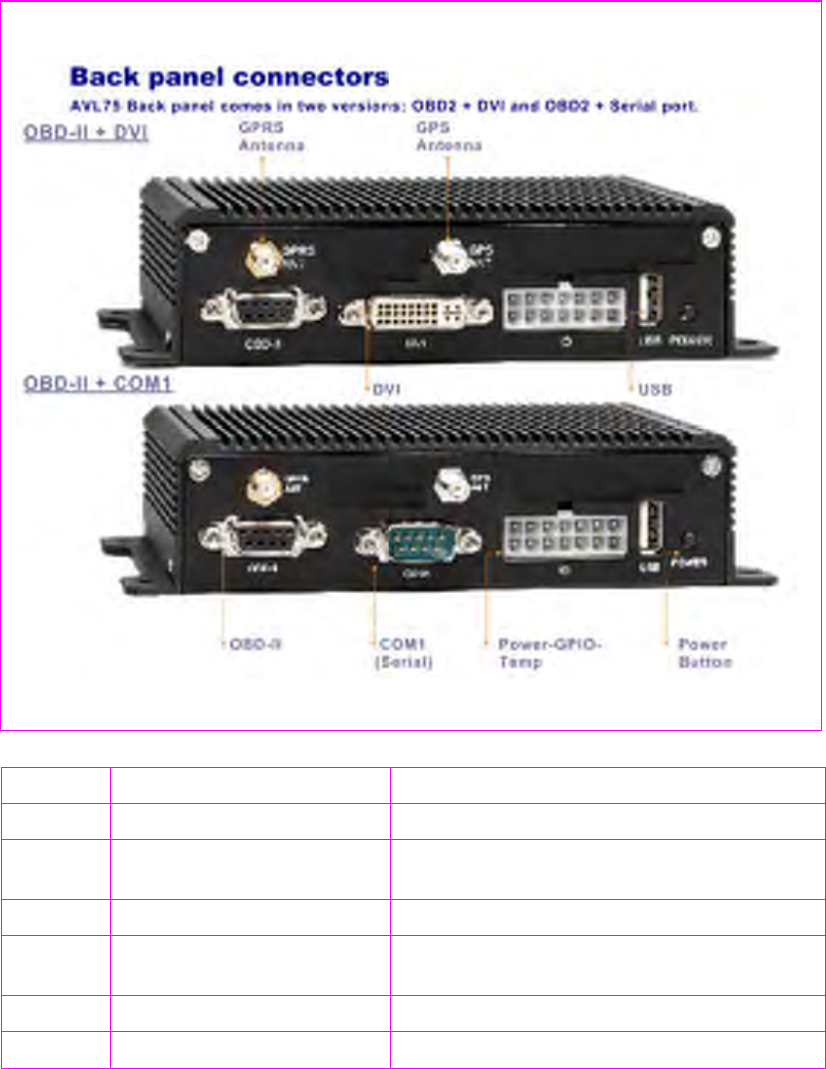
6.3. EXTERNAL CONNECTOR SUMMARY
TABLE 8. There are nine visible connectors and one power switch as follow:
/J1(DM39) FME connector (SMA) GSM Antenna attachment
J8 SMA connector COM3 / GPS Antenna attachment
J12 RS232C connector COM2 / GPS Data output (or ODB-II), select
one
J2 DVI connector For DVD player display connection
J17 Double line, 7-Position
connector For Power source, GPIO connection
J5 USB Type A connector USB1.1 connection
S2 2-Pole push button switch Power switch
Note: For Pin Assignments, please refer to Appendix A for details.
AVL75 Back panel comes in two versions: OBD2+DVI and OBD2+Serial port.
FIGURE 6.2 : Back panel connectors overview
14
Chapter 7
7. General Hardware Specification
AVL75 is the main operating hardware unit of the system is intended for installation in a vehicle.
The main operating unit (AVL75) represents equipment for vehicle easy locating in the real time
mode with the help of Internet based application software. With the help of security subsystem the
costumer obtains a lot of possibilities to resist the hijacking of the vehicle. With the help of
MapPoint© or OziExplorer© mapping software, or costumer’s own scanned maps. it is very easy to
locate the vehicles up to street level.
Note: MapPoint© and OziExplorer© are the copyright of Microsoft and Des Newman respectively.
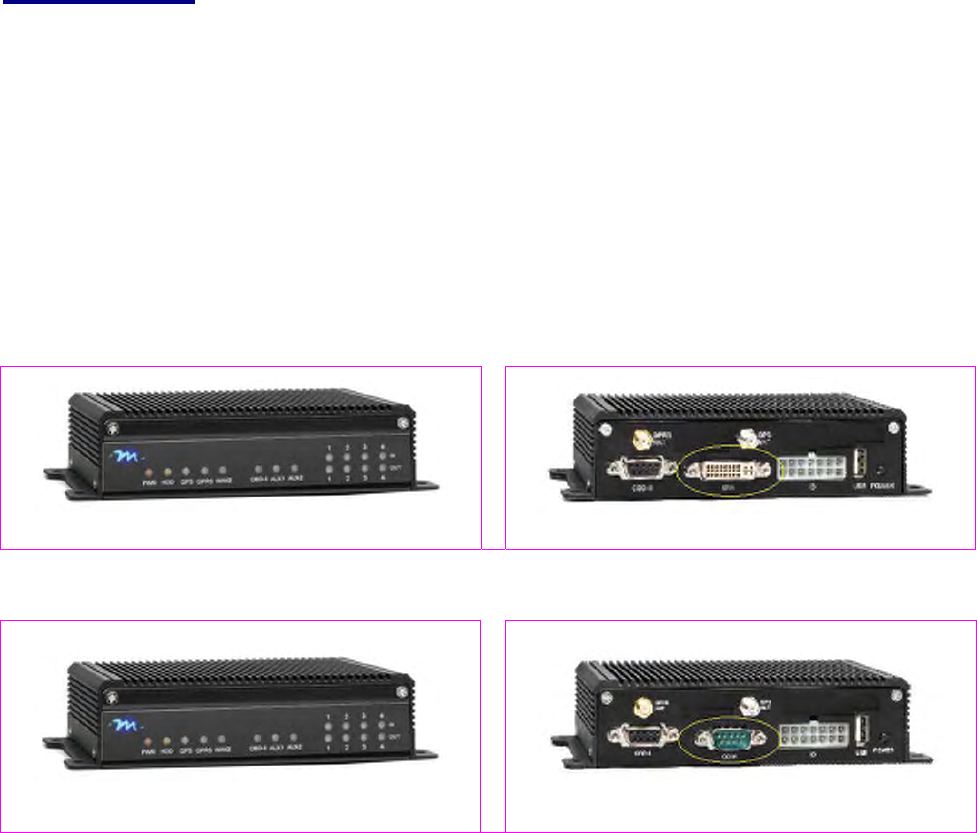
AVL has two versions with similar selective communication function:
First version: OBD2 + DVI
Selective communication: GPRS Modem and OBD2
Figure 7.1A : AVL750MXB Front Panel Figure 7.1B : AVL750MXB Rear Panel
Second version: OBD2 + Serial port
Selective communication: GPRS Modem and OBD2
Figure 7.2A : AVL750MXB Front Panel Figure 7.2B: AVL750MXR Rear Panel
7.1. About AVL System
The AVL75 unit consists of the following major feature:
1. GPS Internal GPS receiver and active antenna;
2. GSM 3-band Internal GSM/GPRS module 850/1800/1900 MHz and antenna;
selectable for another 3-band option module of 900/1800/1900 MHz
3. OBD-II Vehicle engine diagnosis
4. Digital I/O 4 digital outputs and 4 digital inputs;
5. IDE Flash Disk 32 Mbytes of EmbedDisk (upgradable)
6. Flash 512 Kbytes for data backup;
7. RS232 RS232 interface for notebook/laptop connection;
15
Chapter 8
8. SIM Card Installation
Make sure to place a SIM card of your GSM operator into the AVL75 SYSTEM properly, before
in-vehicle installation. Follow these simple steps:
1. Cancel a PIN code query in your SIM card. You can cancel PIN code from your telephone menu.
For different models, the procedure may vary, though generally Call Barring option is under:
Settings / Security Settings / Access.
2. Make sure that GPRS service is activated - contact your GSM service provider.
3. Find out the exact GPRS service settings of your GSM operator.
4. Make sure there are enough funds on the GSM account
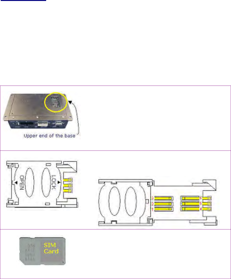
8.1. Steps for SIM card installation
Figure 8.1 : SIM card Lid cover
1. Make sure that the AVL unit is turned off.
2. With the rear panel facing you, turn the AVL unit upside
down. See Figure 8.1.
3. At the upper end of the base, you can find a lid cover, unlock
the screw with a philips screw driver.
4.
T
ake off the lid cover, and you can find a conventional SIM
card holder. See Figure 8.2.
Figure 8.2 : SIM card holder
overview (closed cover)
5. Using your index finger, push softly to the left, to uncover of
the SIM card holder, according to the indicated “OPEN”
direction, and then turn vertically upwards to the open
position.
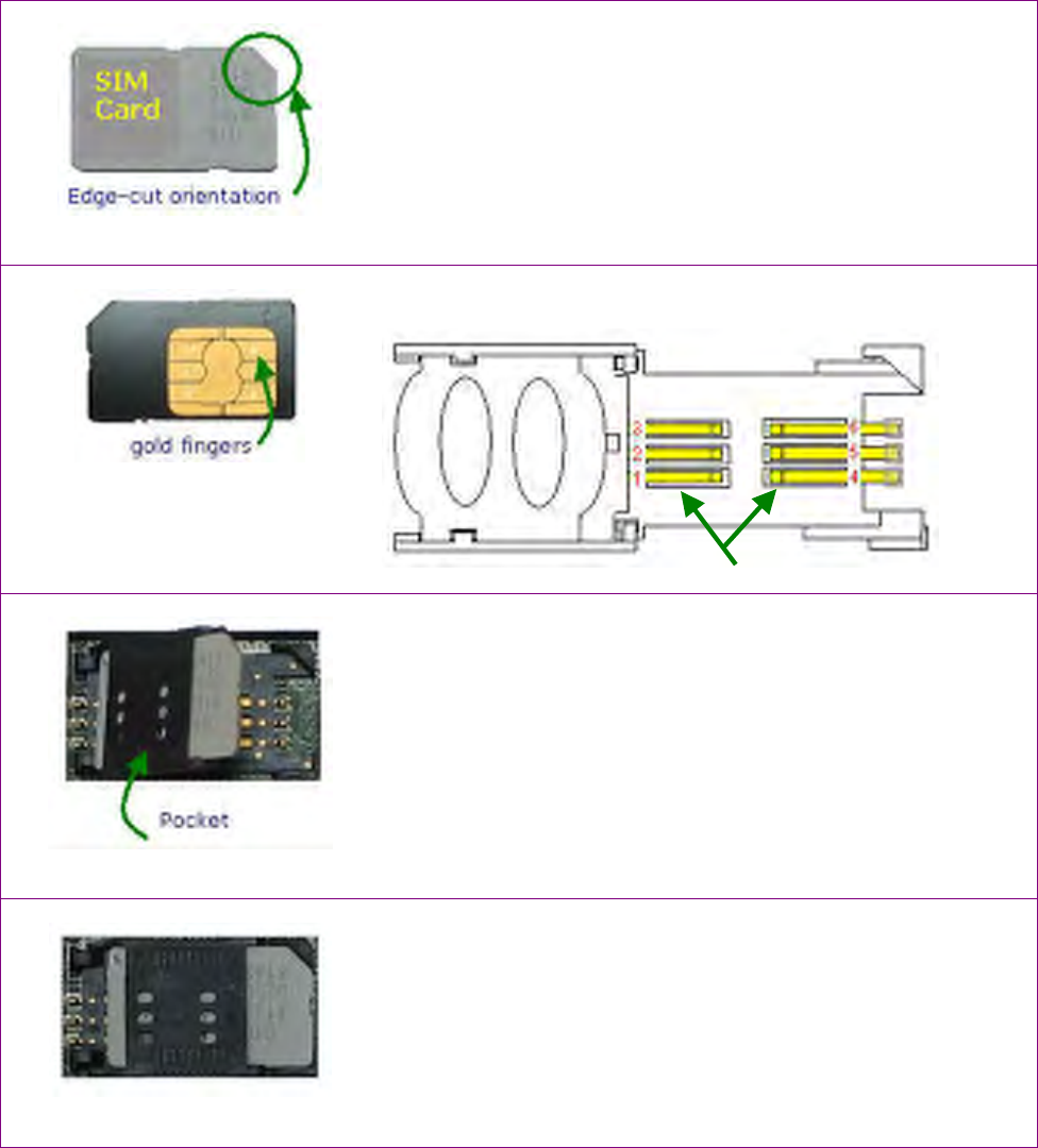
Figure 8.3 : SIM card
6. Get a SIM card from your GPRS service provider, as shown
on the Figure 8.3.
16
Figure 8.4 : SIM card orientation
7. Prepare to install your SIM card, by turning the card to the
position where the cut is facing the correct orientation of the
SIM card holder (See Figure 8.4).
Figure 8.5 : SIM card gold fingers
contact
8. The gold fingers contact of the SIM card must be touching
the contact pins bay of the SIM card holder.
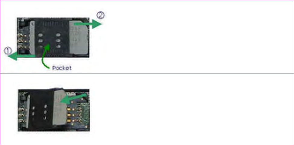
Figure 8.6 : SIM card holder pocket
9. Use the tweezers to avoid the printed circuit board’s
damage, insert gently the SIM card into the SIM holder of
the GSM modem module according to the picture.
10. Slide the SIM card to the pocket of the SIM card holder.
Figure 8.7 : SIM card holder closed
11. Push the pocket downwards parallel to the contacts of the
SIM holder. And slowly push the pocket to the right
position with your fingers until the pocket is hold uptight
and locked.
Contact pins bay
17
8.2. Reverse procedure for replacing a SIM card
1. To open the SIM card holder, using your fingers, push the
plastic lid to the left position, and flip-up to open.
Indication as Push to the left, then Hold the lift
upwards.
2. Remove the old SIM card by pulling out the SIM card from
the pocket.
Or
3. Replace with a new SIM card by following the Installation
procedure in section 8.1.
4. Use the tweezers to avoid the printed circuit board’s
damage, insert the SIM card into the SIM holder of the GSM
modem module according to the picture.
5. Slide the SIM card to the pocket of the SIM holder.
6. Attach the front panel back, be aware of unit’s internal wires
disposition; do not squeeze the wires.

18
Chapter 9
9. Software Support
DMP provides the AVL75 hardware solution to the software developers who will develop the A/P and
SQL database for AVL system.
9.1 Summarizing the AVL software
AVL software is divided into 3 categories, namely:
1. Database server and data transmission server
2. Backstage control software
3. AVL client point software.
9.2. Database and Data transmission server
When the AVL client is hooked up online, the data transmission server would first access to the
database to capture the information, then these data is delivered to the client end, and the AVL client
will gather all the needed information and write back to the database in return.
9.3. Backstage control management program
We suggest to use MDI method to convert and write a program (this single program can open many
map windows/GUI), at the same time, read & retrieve database.
9.3.1. This is a new addition of the current windows browsing situation (MAP interface), can either
select single task windows fix locked, or free view mode.
9.3.2 New history information broadcast on the windows site.
9.3.3. All client points history and status summary.
With regards to the client end settings, the backstage program will manage the control. After the
user managed the program settings, he can send the information to the internet for transmission or
transport (remit) to a USB flash memory, then update the client end settings again.
Setting parameters detailed contents are as follows:
1. GPI Event monitoring setting, can be set as GPI event touch off for power-on time and request for
report back of the content of the data. We can also set GPO touch off time and length.
2. Wake on Ring setting, can be set as Wake on ring event touch off for power-on time and request
for report back of the content of the data. We can also set GPO touch off time and length.
3. Wake on timer setting, can be set as Wake on timer event touch off for power-on time and request
for report back of the content of the data. We can also set GPO touch off time and length.
4. OBD-II monitoring setting, can be set as retrieving of OBD-II condition establishment touch off
for power-on time and request for report back of the content of the data. We can also set GPO
touch off time and length.
5. Coordinates monitoring setting, we can set a single client end to move the coordinates within the
coordinates scope, if it is over the range, it will report back and set GPO touch off time and length.
6. Automobile single-stop monitoring is over the limit of monitoring manageable time, can be set to
report back of information, and can also set GPO touch off time and length.
7. Can set partial data transfer to another specific AVL client, or pre-call action.
As far as backstage software, it can be set as password necessary for use, then multiple password
with different authority level (for example, client end is set to monitor the completeness of data.
9.4. AVL Client software part
In accordance to setting and the selection with added decision, and these parameters must report
back to the data transmission server.
19
9.5. Principles of operation
After the installation with the necessary set-up, the AVL75 will start to work immediately. As soon
as the internal GPS receiver catches the GPS signals, the device starts to form the packets with the
geographical coordinates.
If your local place is covered by GSM provider, the unit will periodically transfer the data with
vehicle’s tracking movement history, according to the setting that were set up by the client AVL
application software.
All the vehicle-tracking records are stored in a database accessible through the Web. The control can
check and query any period of vehicle tracing history at any moment round the clock, 24 hours per
day. With the help of a mapping software, the vehicle location could be displayed in the real time
mode any time up to street level.
The AVL unit’s location could be updated in one minute, if vehicle is traveling in areas covered by
GPRS service (up to 5 minutes if GPRS service is not provided by GSM operator and the data could be
transferred by SMS)*.
Tracing records are displayed in a Mappoint® mapping window showing the direction of movement.
You could display the tracing records for any period of time. By using the scanned map images the
clients have a possibility to locate their vehicles in areas not covered by Mappoint© mapping
software. A simple Map Matching Method allows the user easy to create own maps.
In addition, GPS data coded in standard of NMEA 0183 can be outputted via RS232 interface, allows
the connection to the notebook/laptop to get GPS data immediately with the help of mapping
software. A wide range of mapping software has a GPS receiver support (for example, Microsoft
Streets&Tips, MapPoint, OziExplorer)
9.6. System software Overview
The System Software provides an interface between your PC and a Global Automatic Vehicle Location
(AVL) system. Using the software you may locate your vehicle at any moment round the clock, 24
hours per day. You may display the vehicle tracing records for any period of its movement at a detail
maps up to street level. The AVL software provides capability of remote system parameters settings.
Vehicle’s tracing records are automatically stored on a Database. In additional AVL software provides
possibility of remote security system managing.
9.6.1. Installation
Minimum System Requirements for AVL software:
· Operating Systems: Windows CE/Embedded XP(Recommended);
· 166 MHz Intel Pentium processor or equivalent;
· 128 MB RAM (recommended);
· 32 MB available flash disk space.
Note: MapPoint© and OziExplorer© are the copyright of Microsoft and Des Newman respectively.
20
Chapter 10
10. Protocol & Drivers
DMP provides protocols and drivers to application software developers, for the development of their
required application software for vehicle management and communication. In this chapter, we
posted several examples, to aid and to assist your development for the required function.
10.1. SRAM Driver
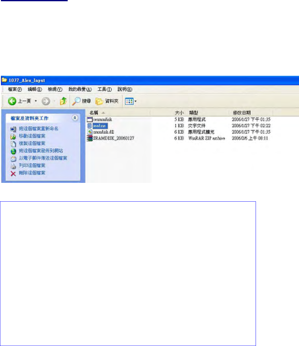
To utilize the SRAM, please extract the ZIP file: SRAMDISK_20060127, as shown on the directory list below:
Open the readme file and follow the steps:
--------- AVL SRAM DISK driver for WIN CE 5.0 ---------
how to install:
1. please copy cesramdisk.exe and sramdisk.dll into
PBWorkspaces\$(WORK SPACE NAME)\WINCE500\$(PLATFORM NAME)\OAK\files\
2. modify project.bib, add these lines
cesramdisk.exe $(_FLATRELEASEDIR)\cesramdisk.exe NK S
sramdisk.dll $(_FLATRELEASEDIR)\sramdisk.dll NK S
3. modify project.dat, add this line
; sram disk loader
Directory("\Windows\Startup"):-File("cesramdisk.exe", "\windows\cesramdisk.exe")
4. sysgen your work space and download image to device,
you will get a new folder name called "SRAM Disk", the disk size will be 504K bytes
There are 512KB SRAM for data backup on AVL. The data can be kept for 7+ days with special battery when AVL
lose power. SRAM also can use as buffer for flash disk to enlarge life cycle. In order to make it easy to use, we
provide SRAM driver for Windows CE. After adding SRAM driver into Windows CE, SRAM will work as a folder.
What programmers have to do is use standard API to read/write files.
End-of-SRAM Driver
21
10.2. Using GPIO on AVL
The GPIO on AVL is from Winbond W83697UF. W83697UF is the LPC (Low Pin Count) interface chip and it also
provides 60 GPIO pins. Those 60 GPIO pins are divided into 8 ports. Here are the GPIO usage and description on
AVL:
Port 2, map to I/O address 610H.
Port Pin ID Type Bit Function
Port20 Output Bit0 "OUT1" LED on AVL panel (Low Active)
Port21 Output Bit1 "OUT2" LED on AVL panel (Low Active)
Port22 Output Bit2 "OUT3" LED on AVL panel (Low Active)
Port23 Output Bit3 "OUT4" LED on AVL panel (Low Active)
Port24 Output Bit4 MC55/56 GPRS Power On control (Low Active)
Port25 Output Bit5 MC55/56 GPRS Power Off control (Low Active)
Port26 Output Bit6 Reserved
Port27 Output Bit7 Reserved
Port 3, map to I/O address 611H.
Port Pin ID Type Bit Function
Port30 Input Bit0 Read IN0 status. The status connects to "IN1" LED
Port31 Input Bit1 Read IN1 status. The status connects to "IN2" LED
Port32 Input Bit2 Read IN2 status. The status connects to "IN3" LED
Port33 Input Bit3 Read IN3 status. The status connects to "IN4" LED
Port34 Input Bit4 Low indicates GPRS modem is power ON
Port35 Input Bit5 GPRS module type ID
Port36 Input Bit6 GPRS module type ID
Port37 Input Bit7 GPRS module type ID
000 is MC55/56 module
111 is SIM 200 module
Port 4, map to I/O address 612H.
Port Pin ID Type Bit Function
Port40 Input Bit0 Reserved
Port41 Input Bit1 Reserved
Port42 Input Bit2 Reserved
Port43 Input Bit3 Reserved
Port44 Input Bit4 Reserved
Port45 Input Bit5 Reserved
Port46 Input Bit6 High indicates OBD-II module is plugged
Port47 Input Bit7 High indicates OBD-II cable is plugged
Port 8, map to I/O address 400H.
Port Pin ID Type Bit Function
Port80 Output Bit0 Output to OBD-II LED (Option)
Port81 Output Bit1 Output to AUX1 LED
Port82 Output Bit2 Output to AUX2 LED
Port83 Output Bit3 LVDS shutdown control (Option)
Port84 Output Bit4 Reserved
Port85 Output Bit5 Reserved
Port86 Output Bit6 Reserved
Port87 Output Bit7 Reserved