DORAN 3604 TIRE PRESSURE MONITORING SYSTEM User Manual Usermanual
DORAN MANUFACTURING, LLC. TIRE PRESSURE MONITORING SYSTEM Usermanual
DORAN >
Users Manual
Manufacturing LLC
Please read this Manual carefully before
using this product.
360RV
Monitors up to 36 different wheel positions

Doran Mfg. LLC • 2851 Massachusetts Ave • Cincinnati, OH 45225 • 866-816-7233 •
Doranmfg.com
2
USER MANUAL
The DORAN 360M is designed solely to monitor tire pressure. It is not designed
to provide warning of a potential or actual tire blowout.
The National Highway and Traffic Safety Administration considers a tire flat
when the pressure is 25% below the tire manufacturers’ recommended operating
pressure. Table of Contents
PAGE
I. Introduction to the Doran 360RV 3-4
Components 4
Glossary of Terms 4
II. Setup and Installation
1. Monitor Installation 5-6
2. Programming the Monitor 6
A. Programming the Sensor Location 7-8
B. Baseline Pressure Programming 9-10
C. Programming the Date & Time for Stored Alarm History 10-11
D. Programming the Unit of Measure 12
E. Delete Sensor Location 12-13
F. High Pressure Alarm Programming 14
III. Installin
g
the Sensor on the Vehicle 15-16
IV.
A
larm Modes
A. First Stage Alarm for 12.5% Low 17-18
B. Second Stage Alarm for 25% Low 18-19
C. High Pressure Alarm 19
D. Lost Sensor Alarm 19
V. Normal Mode Accessor
y
Functions
A. Drop and Hook Feature 20
B. System Reset Function 21
C. Stored Alarm Information 33
D. Backlight for Night Operations 33
VI. Techs and Tips
A. Frequently Asked Questions 22-25
B. Tips 25
C. Limited Warranty 26
D. Specifications 27
Doran Mfg. LLC • 2851 Massachusetts Ave • Cincinnati, OH 45225 • 866-816-7233 •
Doranmfg.com
3
360 RV
I. Introduction
The Doran 360RV is a full-time wireless electronic tire pressure monitoring system (TPMS)
designed to monitor and display tire pressures from 10 psi up to 150 psi. It is capable of
displaying current tire pressure on demand, whether moving or stationary. The 360RV is a
monitoring system and will not prevent tires from losing pressure or failing. However, low
pressure is the leading cause of premature tire failure and the 360RV can provide early notice
of potential problems and assist in maintaining proper pressurization in vehicle tires. The
360RV can be used on all pneumatic tires.
The 360RV consists of two basic components: tire sensors which screw onto the valve stems
of tires, and a monitor. Sensors transmit a coded RF signal and alert if pressure drops. The
monitor displays each tire’s pressure and an audible alert if tire pressures drop. During an alert,
the low tire location is displayed on the monitor, the monitor will display “LOW PRESSURE”,
the current pressure reading for that tire flashes, and an audible alert sounds. The system can
alert at 2 levels: The first alert occurs when pressures drop more that 12.5%. A second more
urgent alert occurs if tire pressures drop more than 25%. As with many RF products, signal
interruption can occur and prevent a signal to reach the monitor. When used properly, the
Doran 360RV will inform the driver of the tire pressures on the vehicle so the operator has the
opportunity to make any necessary adjustments to the air pressure before a serious problem
occurs.
Tires and valve stems should be inspected thoroughly prior to installation of the system to
ensure they are in good condition and inflated properly. It is not uncommon to find valve stems
that need replacing when installing the 360RV system. Doran recommends that rubber valve
stems be replaced with metal stems. Some rubber stems have been found to be inferior and
could fail prematurely.
A visual inspection of tires on a regular basis is recommended. The 360RV does not
prevent low tire pressure, it alerts when tire pressures are low, allowing action to be taken.
A damaged Sensor or valve stem can cause pressure loss. Inspect regularly. If repeated
faults are observed, discontinue use of the system and contact Doran Mfg. at: 1-866-816-
7233.
The 360RV cannot prevent tire/wheel overload. Overloading any tire is extremely
dangerous and can cause the failure of any suspension component, not just tires! The only
way to detect overloading is to weigh the vehicle! A vehicle should never be operated if the
weight on any wheel is greater than the design specification! Even a correctly inflated tire can
fail if overloaded.
Doran Mfg. LLC • 2851 Massachusetts Ave • Cincinnati, OH 45225 • 866-816-7233 •
Doranmfg.com
4
Tires can fail for other reasons besides low pressure or overloading. Always be on the
alert for any other tire problems as indicated by unusual noises, vibrations, uneven tread wear,
or bulges on the tire! If any of these symptoms occur, have the tires checked immediately by a
professional!
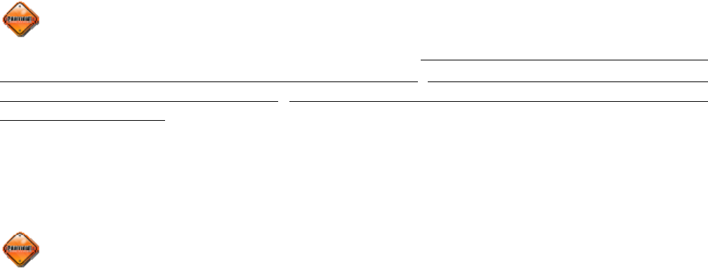
If you are missing any of these components, DO NOT proceed with the installation.
Contact the manufacturer for any missing or replacement parts.
Glossary of terms:
Normal Mode: When monitor is monitoring all programmed sensors and there are not any
faults, the monitor will display a green light and the display will show “on”.
Alert Mode: When the monitor has received a signal that is outside of the parameters of the
“Normal Operation” an alert will be displayed with icons describing the fault along with an
audible beeping sound. Pressing the Set or Program buttons can turn off the audible alarm.
Baseline Air Pressure: This is the pressure that is programmed into the monitor to identify
what the pressure is to be in each tire position. The monitor will calculate all alarms from this
setting. The baseline pressure should ALWAYS be set when tires are at ambient temperature.
Ambient Temperature: This is the temperature of the outside air. Tires can heat up
significantly which will change the pressure in a tire. If pressures in the tires are set when the
tire temperature is elevated, it can cause the monitor to give alerts because when the tires cool
the pressure will drop and sometimes this will fall 12.5% below the baseline pressure.
RF: The term used to identify Radio Frequency signals.
SYSTEM COMPONENTS:
(1) Display Monitor W/ Fused cigarette
lighter receptacle power cord.
(1) Sensors for each tire
(1) Sensor Lock w/ wrenches for each tire
(2) Hook & Loop pads for installing Monitor
(2) Visor Clips
(1) Swivel Base mounting bracket
(3) Suction Cups for Mounting
(3) Visor Clip & Hook and Lock Bracket
(1) Dill Pin Gauge
(1) Installation and Operation Manual
Doran Mfg. LLC • 2851 Massachusetts Ave • Cincinnati, OH 45225 • 866-816-7233 •
Doranmfg.com
5
II. Setup and Installation
1. Installing the Monitor
The 360RV
gives the user multiple options for mounting the monitor for viewing. You
have the option to place on the sun visor, attach to the windshield, fasten to the dash,
attach it to the pedestal mount, or the ability to use the hook and loop pads to fasten the
monitor to a flat surface. If you are using the hook and loop pads, we suggest that the
surfaces that you are applying the pads to be cleaned
with alcohol to remove any grease or oils that could
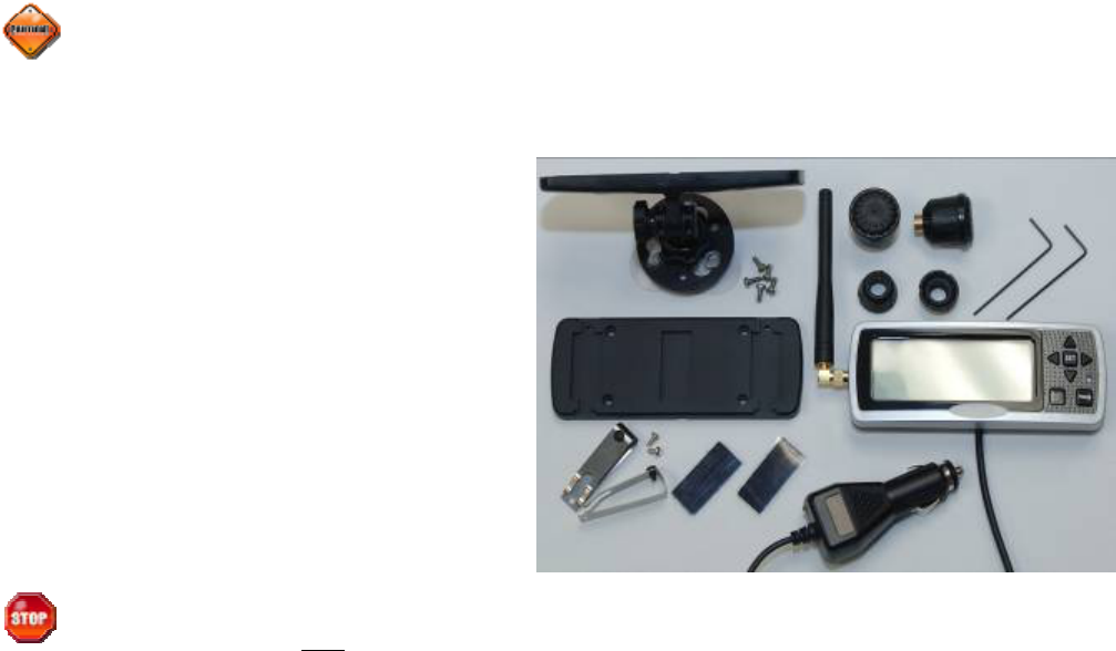
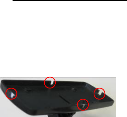
be present. When you have decided on which rear
panel for the monitor that will be correct for your
application you can then remove the correct small
breakaway spot on the chosen back panel for the wire
to exit the monitor in the best direction for your application (see Figure 1-1).
A. The convenient way to wire the monitor is to attach the accessory cigarette lighter
adapter on the power cord to the 12-volt power receptacle. This method is the
quickest, however it does not allow you to receive the full benefits of the Doran
360RV. Using the accessory cigarette lighter adapter plug for your power source
will delay information to the monitor if the power is removed when the vehicle is
turned off and the power is removed from the receptacle. However, if the power
remains on to capture the warnings as they happen in the middle of the night, when
you do not want to be disturbed, the monitor could go into warning modes with
alarms activated and flashing lights when you may not want it to in the middle of the
night while people are sleeping. That is why we suggest that you use option “B” for
wiring your monitor.
B. In order to access the full benefits of the system you will need to hard wire the
monitor to the vehicles’ electrical system. The cigarette power adapter will need to
be removed from the power cord and then you will see that there are three wires in
the harness (we suggest that you leave a few inches of wire on so you can use the
plug at a later date for something else). Red is the 12-volt positive constant
connection. This should be connected to a 12-volt power source that is always “on”.
The Blue wire will be the “switched” 12-volt positive connection. This wire should
only be live when the key is in the “ON” position. The BLACK wire is to be
connected to a good ground. This hookup will allow the monitor to receive signals
when the vehicle is not running, and update the monitor in real time. When the key
Figure 1-1
Doran Mfg. LLC • 2851 Massachusetts Ave • Cincinnati, OH 45225 • 866-816-7233 •
Doranmfg.com
6
is turned on you will have the current information for your tire condition immediately
before you begin your next trip.
The monitor is fused internally, however some installers would still prefer to
install an inline fuse for precautions. We suggest an optional 2-amp fast blow fuse
be used for this purpose.
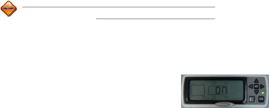
C. The first time the monitor is powered up the display will show “nsP”. This is
saying that there are “No Sensors Programmed” to the monitor. It could be that the
sensors that were programmed to the monitor have not reported in to the monitor in
order to lock the sensors into the memory. If this is the case it could take up to 6
minutes for this to happen. If this is the first time you have attempted to install the
system and the sensors have not been programmed into the monitor, the system will
need to be programmed per the following section.
2. Programming the Monitor
For the monitor to function effortlessly, the user must install the correct data. The
information input to the monitor will allow the monitor to recognize the sensors and wheel
positions as well as the baseline pressures for all tires. This is done in the following steps.
Do not install sensors until all programming is completed and you
have returned to the normal operation mode.
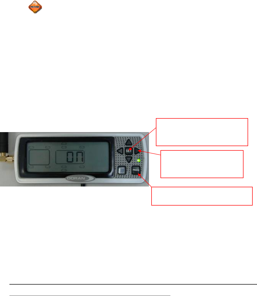
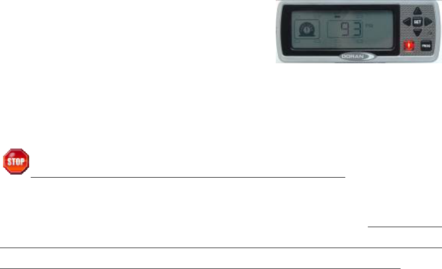
“PROG” Used to enter the program
modes. Also used to silence alarms.
“SET” Used to lock in selections
during programming. Used to
turn on and off the backlight.
(4) Arrow buttons are used to
navigate the screen and select
values in the program mode
Doran Mfg. LLC • 2851 Massachusetts Ave • Cincinnati, OH 45225 • 866-816-7233 •
Doranmfg.com
7
A. Programming the Sensor location
1. Be sure that the power is on. The first time the monitor is switched on; the display
should show “nsP”. This will signify that no sensor is programmed, or the monitor
has not received a new sensor signal yet. If this is the case it could take up to 6
minutes for the sensor to report in if it is already attached to the valve stem. You will
now need to enter into the programming mode if you need to add sensors to the
monitor. If you are entering new sensors into he monitor be sure to leave the
sensors off of the valve stems until the programming is complete.
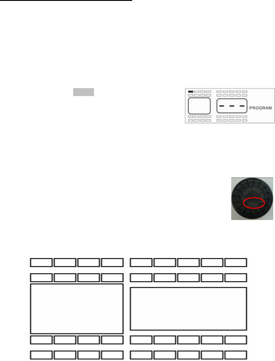
2. Press and hold the PROG button for approximately 5
seconds, the monitor screen will automatically change
over to the program mode, and then you can release
the button. When you have entered this mode the
monitor will display all of the tire positions and the
word “PROGRAM” will be displayed (see Figure 2-1). As you will see by Figure 2-1
the monitor can be set up to display a motor home pulling a car or trailer, or a car /
truck pulling a trailer.
3. Select a tire position using the arrow buttons and input the 3-digit serial number
located on the sensor into the monitor (see Figure 2-2 for the three-
digit number). The monitor will automatically capture the serial
number and information when air pressure is supplied to the sensor
for that wheel position and lock it into the monitor. Be sure to keep
the sensors identified as to which wheel positions they belong so that
you can attach the sensors to their proper location for future
reference. Use the diagram in Figure 2-3 to record the 3 digit numbers onto the
wheel locations that you will be selecting.
Figure 2-1
Fi
g
ure 2-2
Figure 2-3
Doran Mfg. LLC • 2851 Massachusetts Ave • Cincinnati, OH 45225 • 866-816-7233 •
Doranmfg.com
8
4. Using the arrow keys select the first tire position that you want to program. The
selected wheel location will be solid. The other wheel positions will only be an
outline. If sensors have already been programmed to the monitor, the only sensor
locations that will be displayed will be the ones that do not have a sensor already
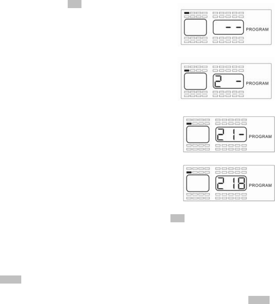
programmed to it. When you have selected the position that you want to program a
sensor to, press the SET button for 3 seconds. This
will cause the first dash (see Figure 2-4) of a three-
digit sensor number to blink that will need to be
entered.
5. Using the up and down arrow buttons, change the first
digit to the first corresponding digit of the sensor ID
number that you want to program. When you have
selected the correct digit press the right arrow button to
move to the next digit in the display.
6. The center dash (-) of this digit will now blink (see
Figure 2-5). Use the up and down button to change
this digit to the number needed for the second digit of
the sensor. When you have selected the correct
number for the center section of this number press the
right arrow button so the remaining dash (-) begins to
flash of the three-digit number (see Figure 2-6).
7. Adjust this position with the up and down button until
you have the correct number displayed. Pressing the
right or left arrow button will allow you to change one of
the numbers that you have previously selected if
needed.
8. If you have the correct number displayed, press the SET button for 3 seconds until
the number flashes twice and you hear a beep twice to signify that the sensor ID
number was successfully input to the monitor (see Figure 2-6a).
9. A new position will be highlighted to input another serial number. If you wish to
program another sensor repeat the above steps in Section A.
10. Once you have completed the sensor programming sequence for all tires, press the
PROG button momentarily to move to the next step, this will be the Base Line
Pressure Programming. The monitor will display as shown in Figure 2-7. If you are
completely done with all of the programming operations you can press the PROG
button for 5 seconds and the monitor will return to the normal mode of operation.
This can be done at the end of any section of the program mode when the
programming is completed.
Fi
g
ure 2-4
Fi
g
ure 2-5
Fi
g
ure 2-6
Fi
g
ure 2-6a
Doran Mfg. LLC • 2851 Massachusetts Ave • Cincinnati, OH 45225 • 866-816-7233 •
Doranmfg.com
9
B. Baseline Pressure Programming
NOTE: To enter directly into this program mode you will need to
press the PROG button for 5 seconds until the “PROGRAM” is
displayed. Then press the PROG button again briefly to enter
this mode (see Figure 2-7 for screen display).
NOTE: to skip this section and go directly to the Programming the Date and Time for Stored
Alarm History Information just press the PROG button briefly 1 time. The display should look
like Figure 2-10. Anytime during this mode you can escape out to the next program mode by
pressing the PROG momentarily.
The baseline pressure has been set in the factory at 100-psi for all wheel positions. We
recommend that you set the baseline pressure at the same pressure as your recommended
Manufacturers’ Operating Tire Pressures for each vehicles tire being monitored. If you want to
change the baseline pressure, or a new sensor is programmed, then follow the procedure
below.
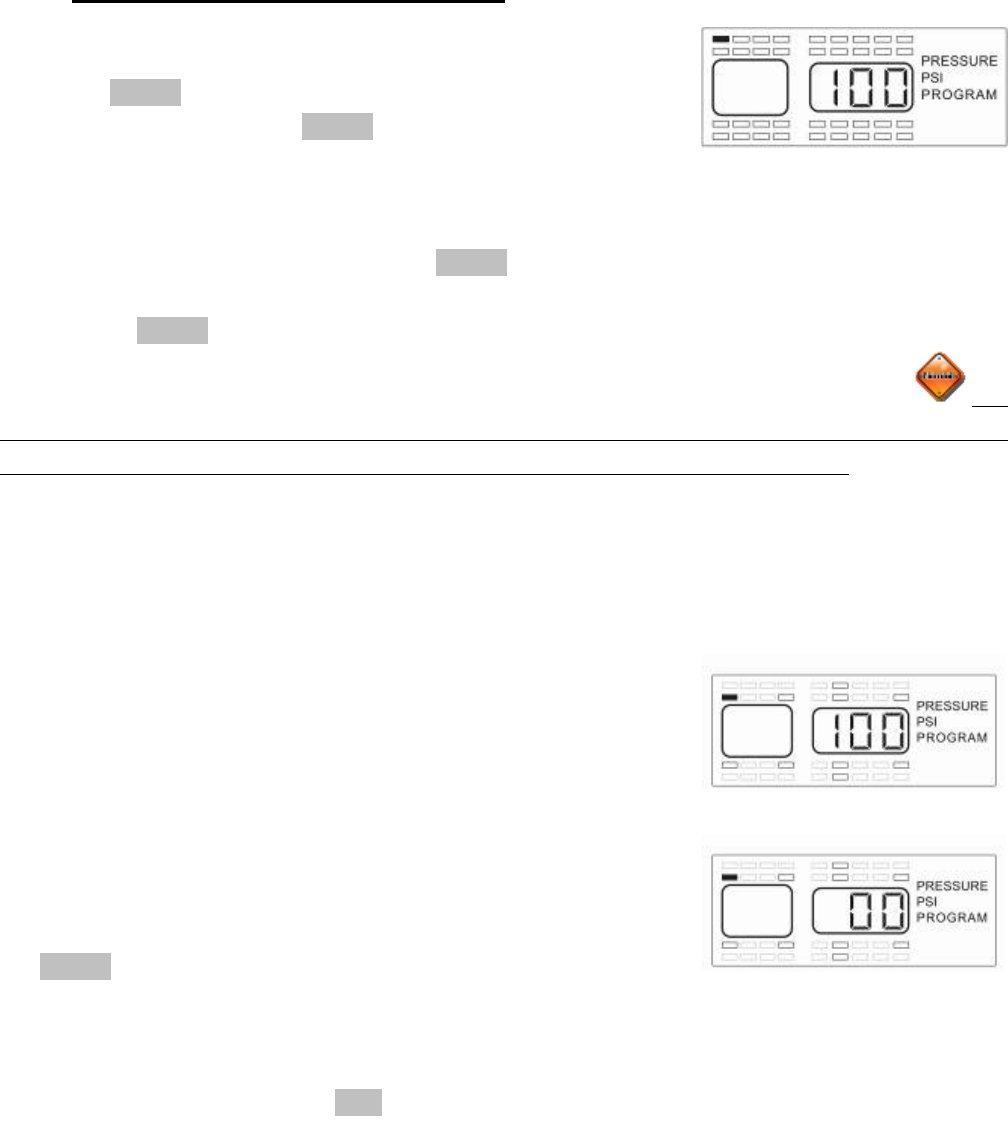
The monitor should now be displaying the wheel positions available to program, the words
PRESSURE, the unit of measure (PSI, Bar, or kPa) and PROGRAM will be displayed as well
as the baseline pressure for the selected wheel position (see
Figure 2-7). The positions that already have sensors
programmed to the monitor will be highlighted at this time (see
Figure 2-8). You can program the air pressure from 5 PSI to
188 PSI, depending on your needs. Each wheel position can be
set with a different baseline air pressure if this is what is needed.
The monitor has been pre-programmed for 100 PSI at each
wheel position. If this is the baseline air pressure that you need
then you will not have to do anything in this mode and can press
the PROG button and go to the next step. If you need to change
the baseline air pressure for a wheel position, continue with
steps 1-4 below:
1. Using the same procedure as done previously, use the arrow buttons to select a wheel
position and press the SET button for 3 seconds. This will cause the first dash or
number to blink (see Figure 2-9) of a three-digit baseline pressure number that will need
to be entered for the tire position selected.
2. The first digit of the three dashes will automatically start to flash. To adjust the air
pressure for the first digit press the up or down arrow button to change the number. For
Fi
g
ure 2-7
Fi
g
ure 2-8
Figure 2-9
Doran Mfg. LLC • 2851 Massachusetts Ave • Cincinnati, OH 45225 • 866-816-7233 •
Doranmfg.com
10
a number less that 100 you will need to start your number with a 0. For the air pressure
of 95 PSI your imputed number for the baseline pressure would be imputed as “095”.
3. Press the left or right arrow button to select the next digit. Use the up and down arrow
buttons to change that digit. When you have entered the number that you want, press
the SET button for 3 seconds until the number flashes twice and a double beep is heard
to signify that the number has been locked into the monitor’s memory.
4. A new position will be highlighted to input a baseline air pressure. If you wish to
program another sensor repeat the steps 1 thru 3. If you have completed the sensor
baseline air pressure programming sequence then you can press the PROG button
momentarily to move to the Time and Date -stamp setting mode. If you are done with
the programming operation you can press the PROG button for 5 seconds and the
monitor will automatically return to the normal mode of operation. This can be done in
any section of the program mode when the programming is completed.
C. Programming the Date and Time for Stored Alarm History Information
NOTE: To enter directly into this program mode you will need to
press the PROG button for 5 seconds until the “PROGRAM” is
displayed. Then press the PROG button again briefly 2 times to
enter this mode (see Figure 2- 10 for screen display).
NOTE: to skip this section and go directly to the Programming the Units of Measure just press
the PROG button briefly 1 time. The display should look like Figure 2-17. Anytime during this
mode you can escape out to the next program mode by pressing the PROG momentarily.
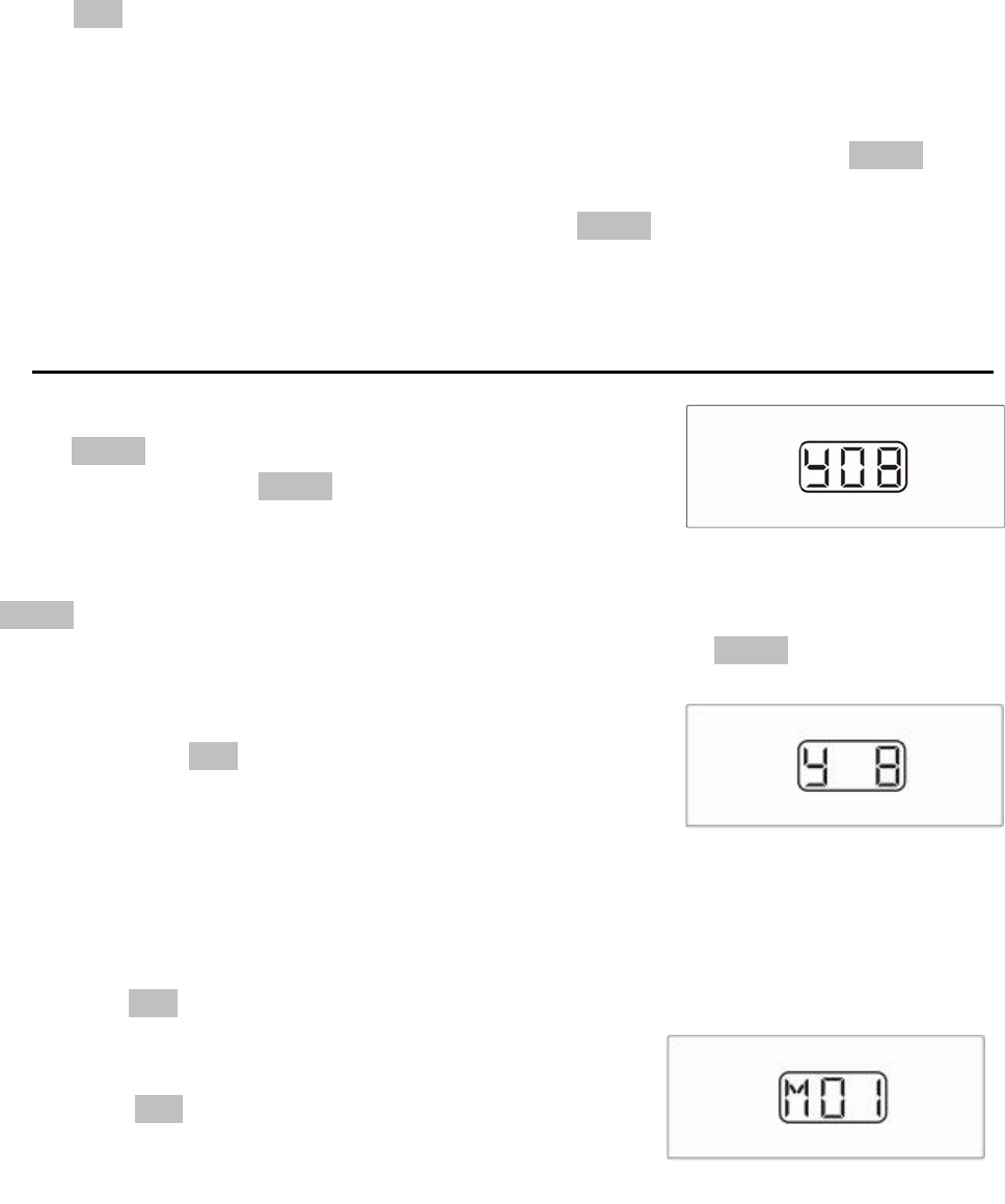
1. The first thing that you will adjust is the Year (Y).
Pressing the SET button for 3 seconds will cause the
center digit after the Y to flash (see Figure 2-11). This
should remain a 0 until the year 2010, and then it will be
changed to a 1. Pressing the up and down arrow buttons
will adjust the value of this digit. When you have selected the number that you want,
press the right button to adjust the right digit in the same manner with the up and down
arrow buttons. When you have the proper number displayed for the year (Y) press and
hold the SET button for 3 seconds until the monitor beeps twice and the display flashes
twice. The monitor will now display like Figure 2-12.
2. To adjust the Month (M) you will need to press and
hold the SET button until the center digit flashes. The
months will be displayed as (01) for January thru (12)
for December. Pressing the up and down arrow buttons
Figure 2-10
Fi
g
ure 2-11
Fi
g
ure 2-12
Doran Mfg. LLC • 2851 Massachusetts Ave • Cincinnati, OH 45225 • 866-816-7233 •
Doranmfg.com
11
Fi
g
ure 2-13
will adjust the value of this digit. When you have selected the number that you want
press the right button to adjust the right digit in the same manner with the up and down
arrow buttons. When you have the proper number displayed for the Month (M) press
and hold the SET button for 3 seconds until the monitor beeps twice and the display
flashes twice. The display is shown like Figure 2-13.
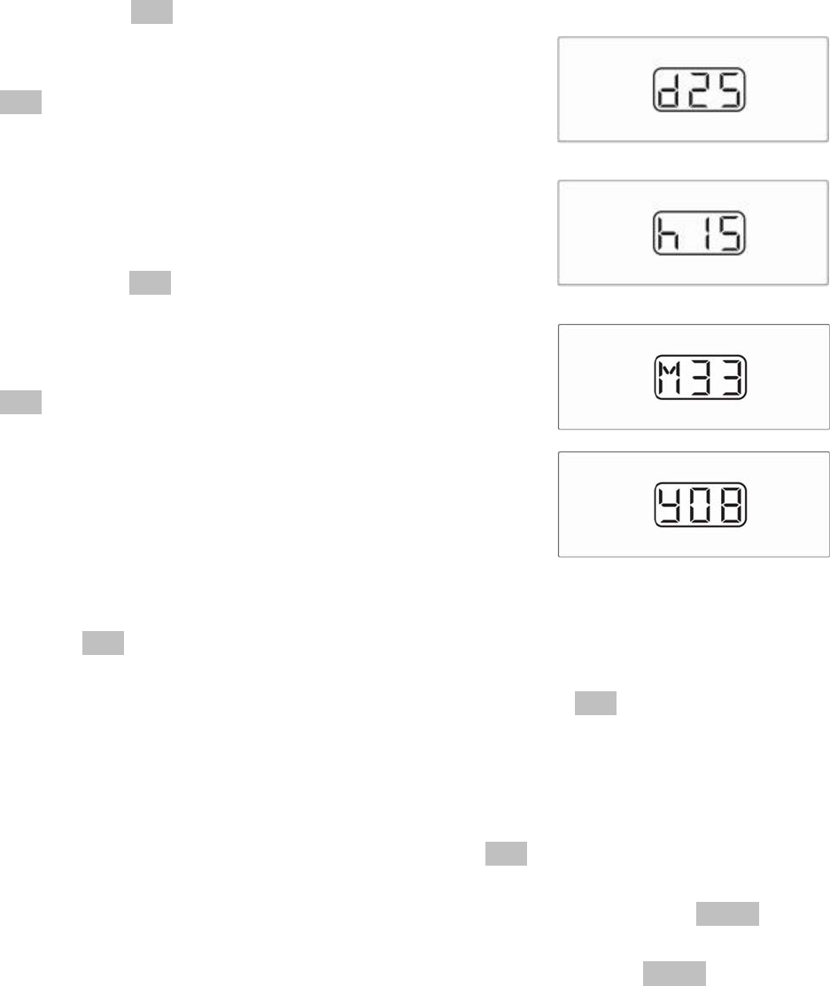
3. To adjust the day (d) you will need to press and hold the
SET button until the center digit flashes. Pressing the up
and down arrow buttons will adjust the value of this digit.
When you have selected the number that you want press
the right button to adjust the right digit in the same
manner with the up and down arrow buttons. When you
have the proper number displayed for the day (d) press
and hold the SET button for 3 seconds until the monitor
beeps twice and the display flashes twice. The display is
shown like Figure 2-14.
4. To adjust the hour (h) you will need to press and hold the
SET button until the center digit flashes. Keep in mind
that the hour will be displayed as a 24-hour clock. An
example is that 3:00 in the afternoon will be shown on the
clock as h15. Pressing the up and down arrow buttons
will adjust the value of this digit. When you have selected
the number that you want press the right button to adjust
the right digit in the same manner with the up and down
arrow buttons. When you have the proper number displayed for the hour (h) press and
hold the SET button for 3 seconds until the monitor beeps twice and the display flashes
twice. The display is shown like Figure 2-15.
5. To adjust the minute (M) you will need to press and hold the SET button until the center
digit flashes. You will notice that the Month and Minute both use the (M). Pressing the
up and down arrow buttons will adjust the value of this digit. When you have selected
the number that you want, press the right button to adjust the right digit in the same
manner with the up and down arrow buttons. When you have the proper number
displayed for the Minute (M) press and hold the SET button for 3 seconds until the
monitor beeps and the display flashes twice. The display is shown like Figure 2-16.
6. This will have brought you back to the (Y) years setting. Press the PROG button
momentarily to move to the Pressure Units Programming Mode (see Figure 2-17). If
you are done with the programming operation you can press the PROG button for 5
seconds and the monitor will automatically return to the normal mode of operation. This
can be done in any section of the program mode when the programming is completed.
Fi
g
ure 2-14
Fi
g
ure 2-15
Fi
g
ure 2-16
Doran Mfg. LLC • 2851 Massachusetts Ave • Cincinnati, OH 45225 • 866-816-7233 •
Doranmfg.com
12
D. Programming the Unit of Measure
NOTE: To enter directly into this program mode you will need to
press the PROG button for 5 seconds until the “PROGRAM” is
displayed. Then press the PROG button again briefly 3 times to
enter this mode (see Figure 2-17 for screen display).
NOTE: To skip this section and go directly to the Sensor Deletion mode just press the PROG
button briefly 1 time. The display should look like Figure 2-20. Anytime during this mode you
can escape out to the next program mode by pressing the PROG momentarily.
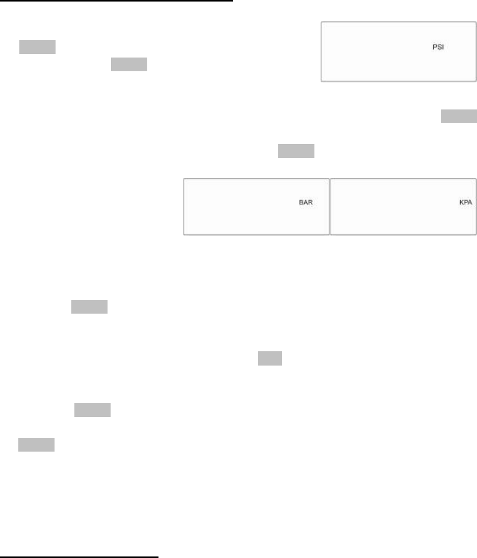
The next step in the programming
mode is to select the unit of measure
for the air pressure. The monitor is set
from the factory to read in PSI (pounds
per square inch) this is the default unit
of measure. The monitor is also capable of displaying the air pressure in BAR and kPa (see
Figure 2-18 and 19). If you want the monitor to read in PSI then nothing needs to be done
except to press the PROG button to move into the next section of the programming mode. To
change the units of measure do the following.
1. Press the left or right arrow to select the words PSI, BAR, or Kpa.
2. When you have your selection press the SET button for three seconds and the
selection should blink twice and the beeper should beep twice to confirm the
selection in the monitors’ memory.
3. Press the PROG button to exit this mode and enter into the Delete Sensor Location
mode next. If you are done with the programming operation you can press the
PROG button for 5 seconds and the monitor will return to the normal mode of
operation. This can be done in any section of the program mode when the
programming is completed.
E. Delete Sensor Location
This step is only used when a sensor is to be removed from the memory of the monitor. This
would be used to remove a sensor from one position and locate it to a different location, or to
remove a sensor. If deleting a sensor is not necessary at this time, please see the second note
below:
Fi
g
ure 2-17
Fi
g
ure 2-18 Fi
g
ure 2-19
Doran Mfg. LLC • 2851 Massachusetts Ave • Cincinnati, OH 45225 • 866-816-7233 •
Doranmfg.com
13
NOTE: To enter directly into this program mode you will need to
press the PROG button for 5 seconds until the “PROGRAM” is
displayed. Then press the PROG button again briefly 4 times to
enter this mode (see Figure 2-20 for screen display).
NOTE: To skip this section and go directly to the High Pressure Alarm Programming mode just
press the PROG button briefly 1 time. The display should look like Figure 2-23 or 2-24.
Anytime during this mode you can escape out to the next program mode by pressing the
PROG momentarily. If you want to return to the normal operation mode press and hold the
PROG button for 5 seconds.
The monitor will display the available sensors to delete and the words PROGRAM and
DELETE will be displayed on the screen (see Figure 2-20). If a sensor does not need to be
deleted you can just press the PROG button to go into the final program mode. If a sensor will
need to be deleted you will need to do the following steps:
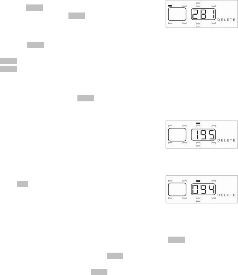
1. Using the arrow keys select the desired sensor that need
to be deleted. The monitor will only display the wheel
positions that have a sensor programmed to that position.
When you select a position the three-digit number that
was programmed will be displayed so you will be able to
verify that this is the correct serial number to delete (see
Figure 2-21).
2. When you have selected the location press and hold the
SET button for three seconds. The three-digit number
will flash twice and the beeper will beep twice to confirm
that this position has been deleted. A different position
will be displayed and the tire location that was deleted
will now be gone (see Figure 2-22).
3. If you have additional sensors that need to be deleted repeat the steps until all required
sensors are deleted. If you need to program deleted sensors to a different location, or
add new sensors to the monitor’s memory simply press the PROG button twice to enter
into the Programming Sensor Location mode (see page 7).
4. When you are finished press the PROG button to enter into the HIGH PRESSURE
program mode, which is the last item to program. If you are done with the programming
operation you can press the PROG button for 5 seconds and the monitor will return to
the normal mode of operation. This can be done in any section of the program mode
when the programming is completed.
Fi
g
ure 2-20
Fi
g
ure 2-21
Fi
g
ure 2-22
Doran Mfg. LLC • 2851 Massachusetts Ave • Cincinnati, OH 45225 • 866-816-7233 •
Doranmfg.com
14
F. High Pressure Alarm Programming
NOTE: To enter directly into this program mode you will need to
press the PROG button for 5 seconds until the “PROGRAM” is
displayed. Then press the PROG button again briefly 5 times to
enter this mode (see Figure 2-23 for screen display).
NOTE: To exit this mode press the PROG button for 3 seconds to return to normal operation
mode
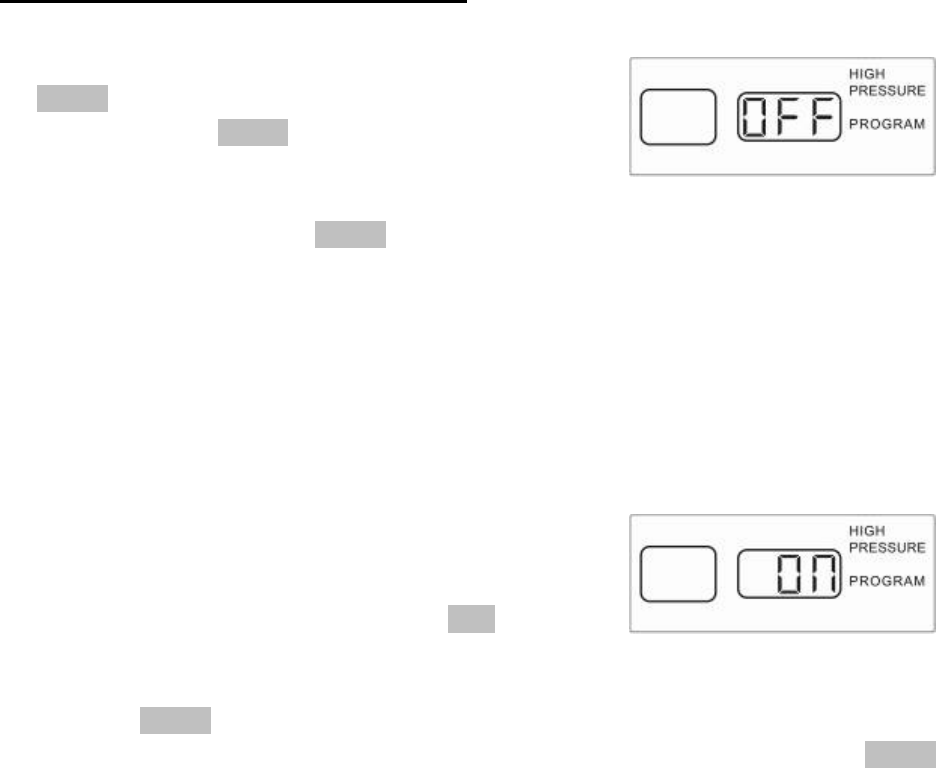
The HIGH PRESSURE PROGRAM mode will allow you to set up your monitor to alarm if a
pressure that is 25% higher than the baseline pressure is detected. This feature can assist in
the checking of elevated heat in the tire. Pressures increase with elevated temperature. The
monitor will display HIGH, PRESSURE, and PROGRAM and the center of the screen will
display “on or OFF” (see Figure 2-23 and 2-24). To turn on or off this feature do the following:
1. Using the left and right arrow buttons you will be able to
turn this feature on and off as it is shown in the center of
the display.
2. When your selection has been made, the SET button will
need to be pressed for three seconds to lock the
selection into the memory of the monitor.
3. Pressing the PROG button briefly will rotate you back through the different programming
modes. If you are done with the programming operation you can press the PROG
button for 3 seconds and the monitor will automatically return to the normal operation
mode. This can be done in any section of the program mode when the programming is
completed.
Fi
g
ure 2-23
Fi
g
ure 2-24
Doran Mfg. LLC • 2851 Massachusetts Ave • Cincinnati, OH 45225 • 866-816-7233 •
Doranmfg.com
15
III. Installing the Sensors on the vehicle.
The monitor should now be turned on and it should be in the normal operation mode.
It could take up to six (6) minutes for the monitor to receive the updated signal from
the sensors once the monitor has been activated if the monitor was powered down.
Be sure to inspect and replace any defective or cracked valve stems before
installing the sensors. If replacements are necessary we
suggest replacing the valve stems with a metal stem. It does improve
the life of the stem due to premature failure from drying out and
cracking. Inferior stems have been found in the market and can cause
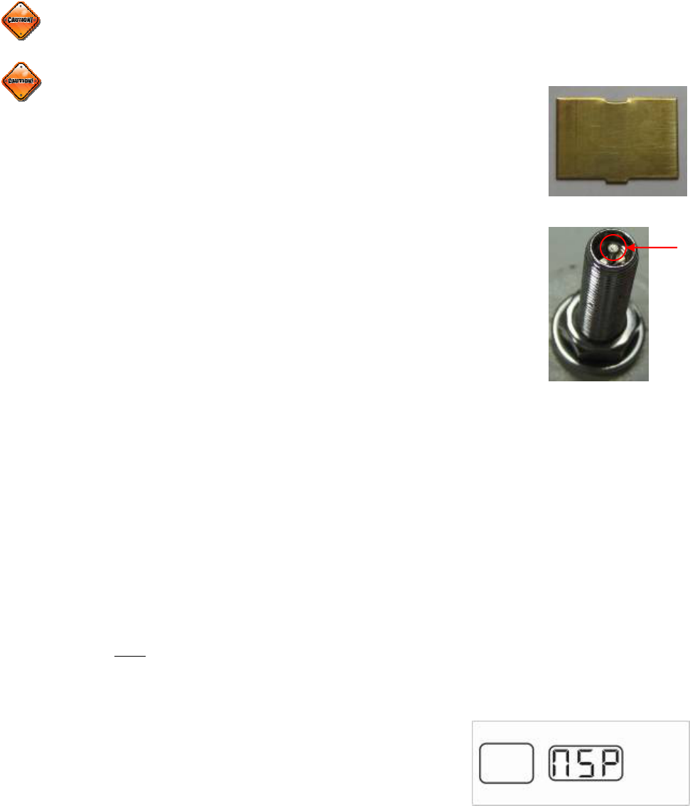
extensive damage. The dill valve at each tire position should now be
checked to see if it is in the proper position to allow the sensors to be
activated by the air pressure from the tires. This can be done using the
enclosed Dill Pin Gauge (see Figure 3-1). When the gauge is used it
should depress the dill pin enough to allow air to escape the valve stem
(see Figure 3-2). If air does not escape from the valve stem, then you
must use a Valve stem tool to adjust the dill pin out far enough to allow
the dill pin tool to release air from the valve stem. This should not be necessary with the
Doran RV360. The dill pin should not be extracted to the point that air is released all the
time from the valve stem. This should be checked with a bit of soapy water if you do make
an adjustment to the dill valve and after the sensors have been installed.
Keep in mind that tire pressures will increase as you drive. When tires are in motion, the
sidewalls are under stress carrying the load of the vehicle. This energy created by the tires
develops heat, which causes the air in the tires to expand. This can cause air pressure to
increase as much as 10 psi in certain applications. This is normal, and the manufacturers’
recommended cold running pressures have already taken this into consideration. Always
adjust air pressure when tires are cold or ambient to the baseline pressures that were
programmed into the monitor for each wheel position. Cool temperatures and high altitudes
can cause tires to lose pressure. If a tire is close to its low-
pressure level, an alert can be sounded when pressure
drops overnight due to cooler temperatures. Inflate to proper
level in the morning. If sensors have not been programmed Figure 3-3
Fi
g
ure 3-1
Fi
g
ure 3-2
Dill
Pin
Doran Mfg. LLC • 2851 Massachusetts Ave • Cincinnati, OH 45225 • 866-816-7233 •
Doranmfg.com
16
to the monitor, or signals received by the monitor after first installed the screen will display
“nsP” (see Figure 3-3).
1. If the sensors have been programmed to the monitor you will now need to install the
sensors onto the proper wheel positions on the vehicle.
The sensor should be tightened only by hand, not with a tool. Use a firm grip
and tighten the sensor. Check for leaks with a soapy solution. The monitor will
begin to receive and recognize the sensors, and it will display the wheel positions as
they are received on the screen.
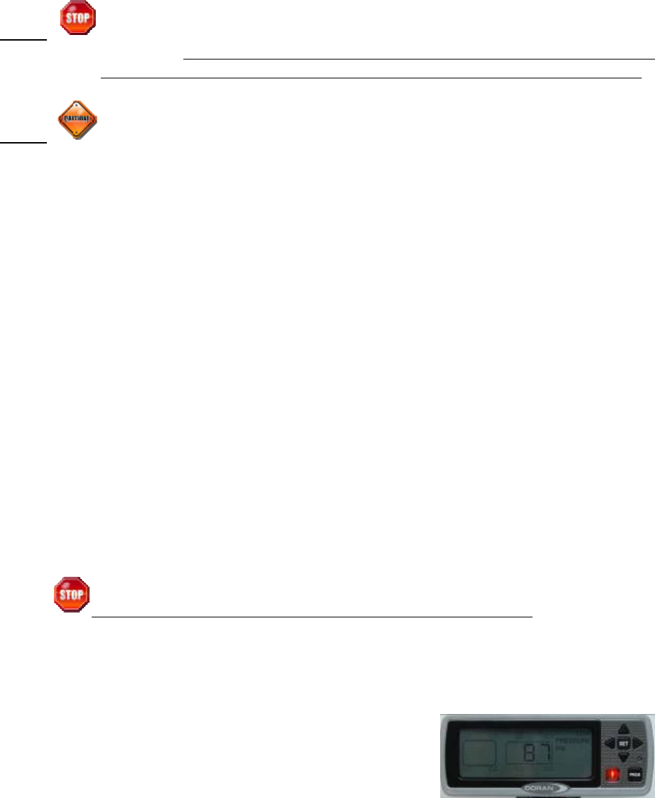
2. When all the sensors that have been programmed to the monitor are received and within
the baseline air pressure parameters, the display will show all the wheel positions that
were programmed, the word “on”, and “PSI” will be
displayed, on the screen, and the green LED light will
come on (see Figure 3-4). You are now ready to enjoy
the safety and comfort of your new Doran 360RV Tire
Pressure Monitor System.
3. If any of the wheel positions are not within the baseline air pressures an alert will be
issued by the monitor and the air pressure reading will be shown for the affected tire
position and the monitor will show PRESSURE and whether it is a LOW or HIGH
warning. The audible alarm will be heard (see Section IV for further details about
alarms).
4. If the monitor continues to search for a sensor after 10 minutes it is possible that the
sensor may not be programmed properly. Higher radio frequency (RF) transmissions
travel mostly via straight lines and along line-of-sight pathways. The 360RV sensors are
required to accomplish the difficult task of transmitting a low power FCC approved signal
from vehicles’ tires to the monitor. If a sensor fails to be recognized, move the monitor
slightly. The vehicle could be in what is known as a “Dead Zone”, this is where the
signal is not able to travel because of its surroundings (pole barn siding, metal fence,
side of a building). Moving the vehicle just a few feet can sometimes overcome this
problem. The sensor will need to be removed and re-installed to activate the sensor for
it to report quickly to the monitor. If you are using an optional signal booster kit,
reposition the booster for a possible better reception.
Figure 3-4
Doran Mfg. LLC • 2851 Massachusetts Ave • Cincinnati, OH 45225 • 866-816-7233 •
Doranmfg.com
17
IV. Alarm Modes
NOTE: An alert indicates that you are operating your vehicle in a dangerous
condition. When the low pressure light illuminates, STOP and check your
tire(s) as soon as safely possible, and inflate them to the proper pressure.
NOTE: The DORAN 360RV will illuminate a flashing low tire pressure warning light
and an audible alarm for three minutes when the inflation pressure in one
or both tires is equal to or less than 12.5 % below the programmed
baseline air pressure. The warning will continue to illuminate as long as
the malfunction exists, whenever the monitor is switched on.
The Doran 360RV has five types of alarm modes. The warning levels are:
12.5% below the programmed baseline air pressure for the first low-level alarm.
The next alarm level is 25% below the programmed baseline air pressure.
There is also a FAST LEAK warning when 2.8 PSI is lost from the tire in less
than 12 seconds.
The optional HIGH PRESSURE warning can be selected when you program the
monitor. This alarm will react when the air pressure increases 25% above the
programmed baseline air pressure.
A LOST SENSOR alarm when the monitor does not receive the RF signal from
the sensor.
1. FIRST STAGE ALARM FOR 12.5% LOW AIR PRESSURE:
On a first level low pressure alarm the monitor will alarm at 12.5% below the
programmed base line air pressure. When this happens the backlight on the
monitor screen will light up. The green led light will go out, the Red warning light
will begin to flash and the audible beeper will cycle
at 1 flash or beep per second, the alarmed wheel
position will be displayed. The pressure of the low
Figure 4-1
Doran Mfg. LLC • 2851 Massachusetts Ave • Cincinnati, OH 45225 • 866-816-7233 •
Doranmfg.com
18
tire, and the words LOW PRESSURE will be displayed on the monitor (see
Figure 4-1). Pressing any of the buttons or after 100 seconds the audible alarm
will be silenced. The monitor will continue to display the wheel position, air
pressure of the alarmed wheel position and the words LOW PRESSURE until the
problem is corrected. If the alarm comes on and
the FAST LEAK icon appears (see Figure 4-2),
this means the tire is loosing air at a rate faster
than 2.8 PSI in a 12 second period. The FAST
LEAK icon will only be displayed during the fast leak and will go out after 18
seconds when the air quits leaking from the tire. We suggest that the tire be
inspected immediately.
2. SECOND STAGE ALARM for 25% LOW AIR PRESSURE:
On a level 2 Low Pressure Alarm the monitor will alarm when the pressure has
reached 25% below the programmed baseline air pressure. The National
Highway and Traffic Safety Administration considers a tire flat when the pressure
is 25% below the tire manufacturers’ recommended operating pressure. When
this happens the backlight on the monitor screen will light up. The green led light
will go out, the red warning light will begin to flash and the audible beeper will
cycle at 2 flashes or beeps per second, the alarmed wheel position will be shown,
the pressure of the low tire, and the words LOW PRESSURE will be displayed on
the monitor similar to Figure 4-1. The screen will display the same information as
a Low Pressure Level 1 Alarm. Pressing any of the buttons or after 100 seconds
the audible alarm will be silenced. The monitor will continue to display the wheel
position, air pressure of the alarmed wheel position and the words LOW
PRESSURE until the problem is corrected. If the alarm comes on and the FAST
LEAK icon appears (see figure 4-2), this means the tire is loosing air at a rate
faster than 2.8 PSI in a 12 second period. The FAST LEAK icon will only be
displayed when a fast leak is detected and will go out after 18 seconds when the
air quits leaking from the tire. We strongly urge you to pull over and inspect the
possible tire damage immediately.
Figure 4-2
Doran Mfg. LLC • 2851 Massachusetts Ave • Cincinnati, OH 45225 • 866-816-7233 •
Doranmfg.com
19
When the low pressure light illuminates, STOP and check your tire(s) as
soon as safely possible, and inflate them to the proper pressure. Driving
on a significantly under-inflated tire can cause the tire to overheat and lead to tire
failure. Under-inflation also reduces fuel efficiency and tires tread life, and may
affect the vehicles’ handling and stopping ability.
3. High Pressure Alarm:
The Doran RV360 monitor is capable of monitoring for a High Pressure Warning.
This is a warning that is displayed when the baseline air pressure is exceeded by
25%. When this happens the Green light will go out. The audible beeper will
beep once per second and HIGH PRESSURE will be displayed on the monitor
screen. This can be caused by extreme heat generated into the tire.
When the High-Pressure warning appears, STOP and check your tire(s)
as soon as safely possible, and check for the possible cause. This can
happen because of a dragging brake, bad wheel bearing, extreme temperature
conditions, or other mechanical failures that you might not detect. It is suggested
that you check the suspect tire position for a possible mechanical failure.
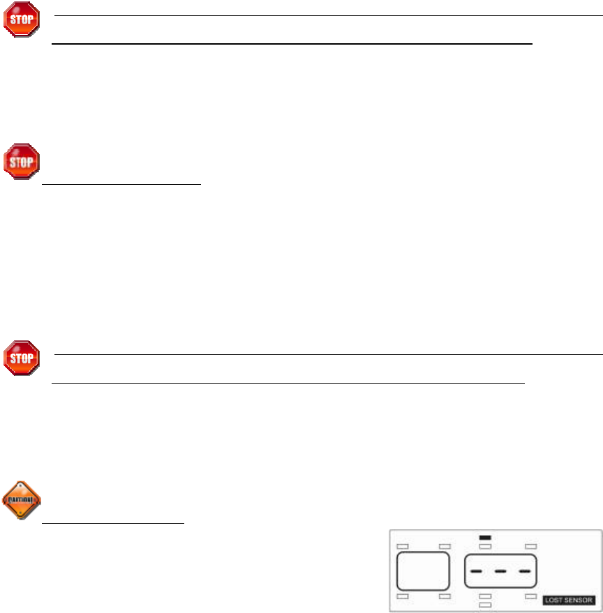
4. Lost Sensor Alarm:
The Doran RV360 monitor is capable of
monitoring for a lost sensor signal (see Figure 4-3).
If the monitor is unable to receive a signal from a
sensor for more than 18 minutes an alarm will be
displayed for that sensor. This does not mean that the sensor is missing, just that
a signal was not able to get to the monitor. This could be from other signals
interfering with the sensor signal, interference from structures, or a poor signal.
By FCC rules we must allow signals from other sources to interfere with our
signals. The Doran 360 series sensors, as well as all the other TMPS systems
on the market are not allowed to interfere with other radio frequency (RF) signals.
Fi
g
ure 4-3
Doran Mfg. LLC • 2851 Massachusetts Ave • Cincinnati, OH 45225 • 866-816-7233 •
Doranmfg.com
20
Fi
g
ure 5-2
V. NORMAL MODE ACCESSORY FUNCTIONS
1. Drop and Hook Feature
This feature allows the operator of the vehicle to drop the monitoring of either the front
or the rear vehicle allowing the monitor to only receive the RF signals from the vehicle
that is in close proximity to the monitor. The operator can drop the trailer and still
monitor the car or truck when trips are required without the trailer. The operator of an
RV can drop the tow car if it is not required. The process is as follows:
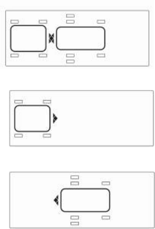
1. Press the front and rear arrow buttons together
for 3 seconds.
2. All of the programmed wheel positions will be
flashing (see Figure 5-1).
3. Press the front or rear button to select the front,
back or both sections for the system to monitor.
The section that is not selected will drop from the
screen (see Figure 5-2 and 5-3).
4. When your selection is made press both the front
and rear arrow buttons for 5 seconds and this
will lock your selection into the monitor. You will
be able to monitor the selected wheel positions
as you did when the system was fully operational. The monitor will go into the
normal operation mode displaying “On” and the green light will be on if the
signals have been received and they are with-in the baseline air pressure
ranges.
5. To change or return to the fully operational monitor method repeat the
previous instructions in this section. When you change or add a section to the
monitor it can take up to 6 minutes for the monitor to capture all of the signals
that were not previously being monitored. The monitor will return to the
normal mode when all selected sensors have reported in and there are no
faults.
Fi
g
ure 5-1
Fi
g
ure 5-3
Doran Mfg. LLC • 2851 Massachusetts Ave • Cincinnati, OH 45225 • 866-816-7233 •
Doranmfg.com
21
Fi
g
ure 6-1
2. System Reset Function
The monitor can be reset to the factory defaults in one easy step. This will erase all of
the serial numbers from the memory of the monitor and will then need to be re-
programmed in order for the monitor to read the sensor signals.
Be sure this is what you want to do before you proceed.
• Press and hold the PROG button for 30 seconds. This will erase all
sensor information and return the monitor to its factory defaults.
3. Stored Alarm Information
The Doran 360RV has the ability to store the last 10
alarm faults that have occurred. They cannot be erased;
they can only be replaced by newer, more recent alarms.
This can be useful if a history of alarms is necessary. It
is unlikely that the typical RV enthusiast will require this
feature. Monitoring the faults and when they occur can
be a useful tool for the over the road trucking industry.
To enter this function, press the PROG and SET
buttons together for 3 seconds. A number 1 will be
displayed on the screen (see Figure 6-1). If no other
buttons are pressed within 1 second the monitor will
automatically start to show the last alarm and then will
show up to the last ten alarms that have occurred from
the most recent to the oldest. If you press the SET
button as soon as you enter this mode you can select
the alarm of your choosing by using the left and right
arrow buttons to select a fault number. Each fault
display will last 3 seconds and then there will be a ½ second pause between each
display until the SET button is pressed to display the next alarm.
Fi
g
ure 6-2
Fi
g
ure 6-3
Fi
g
ure 6-4
Fi
g
ure 6-5
Doran Mfg. LLC • 2851 Massachusetts Ave • Cincinnati, OH 45225 • 866-816-7233 •
Doranmfg.com
22
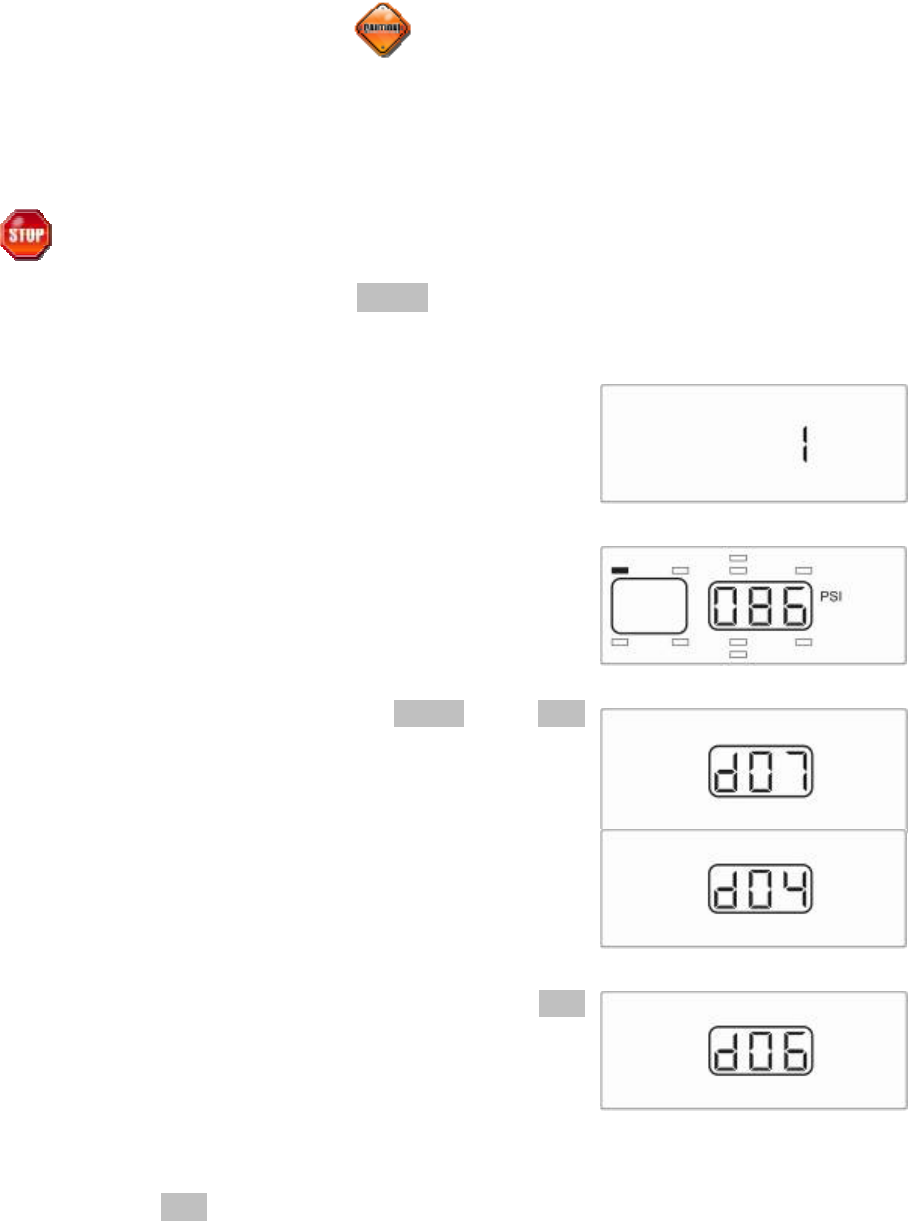
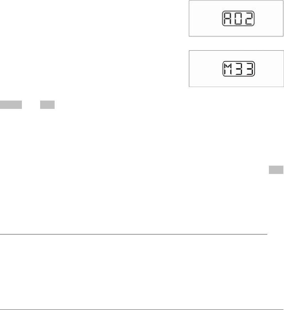
The display will show as follows:
Figure 6-2 Actual pressure for the alarm
Figure 6-3 d07 is for the 7th month or July.
Figure 6-4 d04 is for the 4th day of the month
Figure 6-5 d06 is for the year 2006
Figure 6-6 A02 stands for AM and 2:00
Figure 6-7 M33 Stands for 33 minutes
When you have finished checking the alarm history the
PROG and SET buttons can be pressed together for three seconds to return to the
normal operation mode.
4. Backlight on for night operation
The backlight will automatically come on for any alarm or if you are viewing the wheel
positions in the normal operation mode. The light does not remain on in the normal
operation mode when “On is being displayed. To turn on the Backlight press the SET
button in normal mode and press it again to turn the backlight off.
VI. TECHS-N-TIPS
FREQUENTLY ASKED QUESTIONS
DOES THE MONITOR NEED TO BE POWERED BY A LIGHTER ACCESSORY?
No. In fact you will loose some of the benefits of the 360RV if the monitor is wired in
this method. If a hard wire option is utilized the end user then will benefit from the
sleep mode option that the system incorporates. This will allow alarms to be received
by the monitor but will not allow the monitor to display them or allow the audible alarm
to sound until the ignition switch is turned to the “on” position. This way the people are
not disturbed during an inconvenient time, but does allow for the alarm to be received
before the vehicle is moved.
WHY DID I FAIL TO GET A SIGNAL FROM A SENSOR DURING INSTALLATION?
Higher radio frequency (RF) transmissions travel mostly via straight lines and along
line-of-sight pathways. The 360RV sensors are required to accomplish the difficult
task of transmitting a low power FCC approved signal from vehicles’ tires to the
monitor. If a sensor fails to be recognized, move the monitor slightly. The vehicle
could be in what is known as a “Dead Zone”, this is where the signal is not able to
travel because of its surroundings (pole barn siding, metal fence, side of a building).
Moving the vehicle just a few feet can sometimes overcome this problem. The sensor
will need to be removed and re-installed to activate the sensor for it to report quickly to
the monitor. If you are using an optional signal booster kit, reposition the booster for a
possible better reception.
Fi
g
ure 6-6
Fi
g
ure 6-7

Doran Mfg. LLC • 2851 Massachusetts Ave • Cincinnati, OH 45225 • 866-816-7233 •
Doranmfg.com
23
WHY DOESN’T MY MONITOR TURN ON?
If the monitor only turns on when the vehicle is running, a switched cigarette lighter
receptacle is powering it. A red LED will light on the plug when it receives power.
Check fuse in the end of the lighter accessory plug and if needed, replace with a 2
amp fast-blow fuse. If you have hard wired the system to the vehicle, be sure the
ignition switch is on and check to see if either of the fuses that were installed inline has
blown. Replace all fuses with a 2-amp slow-blow fuse.
HOW DO I MUTE THE AUDIBLE ALERT?
Press any button after the alert sounds. This will put the alert in the Quiet Mode. The
green light will have turned off, the alert will be displayed on the screen, and the
backlight will be lit. This will continue until the alarm has been corrected.
WHAT IF THE GREEN LIGHT ON MONITOR DOES NOT LIGHT?
If the green light on monitor does not come on it will signify that something is not
correct with the settings that were input during setup to the monitor. Review the
information on the display and if a proper air pressure is being displayed be sure that
the baseline for the displayed wheel position was entered correctly.
CAN THE MONITOR BE USED INDEPENDENTLY ON FRONT OR TOW
VEHICLE? Yes – see Drop and Hook Instruction PAGE 20.
CAN I STORE MY VEHICLE LONG TERM WITH THE MONITOR ON?
The monitor draws 60mA to 125 mA of power when it is under power and fully
functional. The monitor could drain vehicle's battery over an extended period of time.
Hooking the monitor up to enable the sleep mode will drastically reduce the power
consumption over a long period. If storing for over 3 months, you might consider
unplugging the monitor and removing the sensors for storage. (TIP: Clean egg
cartons or plastic bags work well for storing the sensors.) Each Sensor has it’s own
serial number laser etched into the cover. Be sure to enter these ID numbers in the
diagram on page 7 so sensors can be replaced on the same tire location when re-
installing them, eliminating the need for reprogramming. If a low-pressure alert is
given while in storage, the sensor will alert until the pressure is corrected and could
dramatically affect the battery life of the sensors. Sensor will shut down and stop
transmitting when less than 5 lbs of air pressure are present. When putting system
back on, power monitor first, and then screw sensors onto their original wheel
locations. Pressure reading will display within a few minutes on the monitor. Your
360RV system will now be active.
HOW DO I CHECK THE TIRE PRESSURES? –The pressures are updated to the
360RV Monitor every 5 minutes under normal circumstances. With the monitor in
Normal Mode, press the SET button and then press the arrow buttons in order to
select a tire’s current pressure to display. When you have finished your inspection
simply press the set button again to return the monitor to the normal mode.

Doran Mfg. LLC • 2851 Massachusetts Ave • Cincinnati, OH 45225 • 866-816-7233 •
Doranmfg.com
24
WHAT HAPPENS WHEN I REMOVE THE SENSORS TO INFLATE OR CHECK THE
PRESSURE IN MY TIRES? It is recommended that tire pressures be checked
regularly using a quality pressure gauge when the tires are at ambient temperatures.
Remove the sensor, check pressure, and inflate if necessary. When you return the
sensor to the valve stem, the sensor will begin to read the current pressure and return
to its normal operation.
With the 360RV system you can air up a low tire with the tire being warm and replace
the sensor without worrying about the sensor giving a false alarm, like some of the
other systems available on the market.
HOW DO I DELETE A SENSOR?
See page 12 for full details on sensor deletion.
WHAT SHOULD BE DONE IF A LOW PRESSURE ALERT IS SOUNDED?
Immediately pull over and check low tire. Physically check tire and repair. Be sure to
check valve stem for damage. Soap stem to identify any leaks.
WHAT MAKES MY SYSTEM SENSORS TRANSMIT?
Sensors will transmit data to the monitor under the following conditions:
1. Sensors update with a signal every 5 minutes.
2. Sensors transmit any change of pressure recognized from the static pressure.
WHAT CAUSES THE MONITOR TO DISPLAY ALARMS?
1. Air pressure has dropped 12.5% of your baseline tire pressure. This alert will
continuously transmit once per second until low pressure is corrected or a
button is pressed to place Monitor in Quiet Mode.
2. Air pressure has dropped to the second alert level, 25% under your
programmed pressures. Alert will transmit twice per second. If a button is not
pressed, unit will alert until pressure is corrected or up to 15 hours.
3. A sensor is removed from its tire.
4. Air pressure is released from the tire at a rate faster that 2.8 psi in less than 12
seconds. This will initiate a fast leak alert.
DO I NEED TO REBALANCE MY TIRES WHEN USING A SENSOR?
The 2/3 oz. sensor on a typical RV or large truck will not normally necessitate
rebalancing tires. Smaller tires may require rebalancing.
WHAT SHOULD I DO IF A SENSOR IS LOST OR DAMAGED?
If a Sensor is lost or damaged and needs replacing, call Doran Mfg. LLC toll free at 1-
866-816-7233 to order a new Sensor.

Doran Mfg. LLC • 2851 Massachusetts Ave • Cincinnati, OH 45225 • 866-816-7233 •
Doranmfg.com
25
MY SENSOR WAS BLOWN OFF, (BLOWOUT) WITH NO ALERT GIVEN
Instant tire failure is rare in comparison to the more common failure caused by gradual
tire deflation. It is possible, during an instantaneous blowout, to have the sensor
blown off the tire before it has had a chance to send a signal to the monitor. The
360RV is not designed for this type of tire failure. Tire failure referred to as a blowout,
is commonly due to low tire pressure resulting in an overheating of the tire sidewalls to
the point of disintegration. The DORAN 360RV is designed solely to monitor tire
pressure. It is not designed to provide warning of a potential or actual tire blowout.
TIPS
TIRE CONDITION: Conduct a regular visual inspection of the vehicles tires. The
sensors are not a substitute for proper tire maintenance and it is the user’s
responsibility to maintain proper amounts of tire pressure and respond accordingly to
warnings and alerts. Low tire pressure is not the only problem associated with tires.
Therefore, symptoms such as bulges, uneven tread, abnormal noise, etc. should
immediately be brought to the attention of a professional.
ROTATING/REPLACING TIRES: When rotating or replacing tires, mark wheel
location of each sensor. Remove sensors and store in bags or in an egg carton until
work is done, and then return the sensors to their original wheel location. You can
also delete the sensor positions on the Monitor (page 12), and reinstall the sensors per
the instructions on page 6.
RF (Radio Frequency) PRODUCTS:
The
Doran 360RV utilizes RF technology to
transmit a signal between the sensor and the monitor. RF signals are subject to
interference from many types of signals and products, which can cause errors in the
operation of the product. As with cell phones and other types of electronics using RF
signals, signal interruption can occur and cause a lost signal transmission.
REMOTE ANTENNA or INTERIOR / EXTERIOR BOOSTER FOR UNIQUE
APPLICATIONS: Due to the unique features of RF signals and the construction and
interference from electronics on some RVs and Trucks, a coaxial antenna or RF
Booster may be necessary. If needed, contact Doran Mfg., LLC at: 1-866-816-7233.
COOL TEMPERATURES AND HIGH ALTITUDE: These conditions may cause tires
to lose pressure. If a tire is close to its low-pressure level, an alert can be sounded
when pressure drops overnight due to cooler temperatures. Inflate to proper level in
the morning.

Doran Mfg. LLC • 2851 Massachusetts Ave • Cincinnati, OH 45225 • 866-816-7233 •
Doranmfg.com
26
LIMITED WARRANTY
ONE YEAR LIMITED WARRANTY
: Subject to the limitations and exclusions set forth in this Limited Warranty, the
DORAN 360 RV is warranted against defects in material or workmanship that result in a product failure under
normal use during the one-year period following the date of purchase by the original end-user. This Limited
Warranty applies only to claims made by the original end-user and cannot be assigned, transferred or conveyed to
any subsequent users. The exclusive remedy for any product determined by DORAN Mfg. LLC to be defective
within such period shall, at the sole option of DORAN Mfg. LLC, be the repair or replacement of such defective
product, or the refund of the purchase price therefore. No other remedy shall be available.
EXCLUSIONS FROM COVERAGE
: This Limited Warranty does not apply to any claims arising from misuse,
abuse, unauthorized repair or alteration, circumstances where the DORAN 360RV is improperly installed or
improperly wired contrary to the DORAN 360RV product instructions; or damage or defect attributable to fire or
other casualty, including, without limitation, acts of God or exposure to abrasive or corrosive materials or
pollutants, or attributable to collision or other accidents involving motorcycles upon which the DORAN 360RV is
installed.
LIMITATIONS
: THIS LIMITED WARRANTY IS EXPRESSLY IN LIEU OF ALL OTHER EXPRESS OR IMPLIED
WARRANTIES, INCLUDING WITHOUT LIMITATION, THE IMPLIED WARRANTY OF MERCHANTABILITY AND
THE IMPLIED WARRANTY OF FITNESS FOR A PARTICULAR PURPOSE, AND ALL OF ALL OTHER
OBLIGATIONS OR LIABILITIES ON THE PART OF DORAN MFG. LLC. THIS LIMITED WARRANTY
SPECIFICALLY EXCLUDES ALL INCIDENTAL, SPECIAL, OR CONSEQUENTIAL DAMAGES. IN NO EVENT,
AND FOR NO CAUSE WHATSOEVER, SHALL DORAN MFG. LLC HAVE ANY LIABILITY TO ANY PARTY IN
EXCESS OF THE ORIGINAL PURCHASE PRICE OF THE PRODUCT IN QUESTION.
EXCLUSIVE AGREEMENT
: This Limited Warranty is a complete and exclusive statement of the warranties which
apply to the DORAN 360RV. There are no express or implied warranties beyond those expressly stated above.
No employee, agent, dealer or other person is authorized to give any warranties on behalf of DORAN Mfg. LLC,
except as authorized in writing.
STATUTE OF LIMITATIONS
. In purchasing the DORAN 360RV you agree that any action for breach of contract
or warranty must be commenced within one year after the cause of action has accrued.
PROCEDURE
: Products determined to be defective within the terms of this Limited Warranty should be returned
to Doran Mfg. LLC, transportation prepaid. Call DORAN Mfg. LLC for return authorization. No unauthorized returns
shall be accepted. Sender is responsible for all costs incurred in the removal or reinstallation and shipping of the
returned product. A copy of the sales slip from the point of purchase must accompany the returned product.
APPLICABLE LAW
: The internal laws of the State of Ohio, U.S.A. shall govern this Limited Warranty, and the
exclusive venue for any dispute in connection with the purchase or use of the product shall be the state and
federal courts of general jurisdiction located in Hamilton County, Ohio U.S.A.
SPECIAL NOTICE TO CONSUMERS
: If you have purchased this product for person, family or household use:
(1) Some states do not permit disclaimers or term limitations of implied warranties so that the
disclaimers and limitations in this Limited Warranty may not apply to you;
(2) Some states do not permit the exclusion or limitation of incidental or consequential
damages so that the exclusions and limitations in this Limited Warranty may not apply to
you; and
(3) This Limited Warranty gives you specific legal rights and you may have other rights that
vary from state to state.
For Warranty Return Authorization
Call Toll Free: 1-866-816-7233

Doran Mfg. LLC • 2851 Massachusetts Ave • Cincinnati, OH 45225 • 866-816-7233 •
Doranmfg.com
27
SPECIFICATIONS
SENSOR
Sensor Transmit Range Approx. 100’ (line of sight)
Operating Frequency 434.1 MHz FM
Operating Temperature Range -40 F to +257F
Storage Temperature Range -40F to +257F
Sensor Weight Approx .85 oz
Sensor Dimensions 1.31”h x 1.16: diameter
Sensor Batteries Internal, non-rechargeable
Sensor Pressure Range 10 to 188 psi +/- psi over operating pressure range
Sensor Low Voltage Shutdown 2.2 Volts
MONITOR
Monitor Power Requirements 12 VDC; typically draws 25 mA in the standby mode.
Less than 100 mA when Alarmed.
Monitor Dimensions 5.7”w x 2.165”h x 1.1” d
Monitor Weight 5.4 oz
Monitor Power Cord Plug Cigarette plug adapter or hard wire
Monitor Tire Positions 1 to 34 positions
Sensor Alarm Trigger Settings 12.5% and 25% below the original tire inflation level
Doran 360RV systems comply with Part 15
Class B of the FCC Rules.
THIS DEVICE COMPLIES WITH PART 15 OF THE FCC RULES.
OPERATION IS SUBJECT TO THE FOLLOWING TWO CONDITIONS
(1) THIS DEVICE MAY NOT CAUSE HARMFUL INTERFERENCE,
AND
(2) THIS DEVICE MUST ACCEPT ANY INTERFERENCE THAT
MAY CAUSE UNDESIRED OPERATION
THE DORAN 360RV IS A DEVICE FOR DISPLAYING TIRE PRESSURES. AS
WITH ALL DEVICES THAT USE RF SIGNALS, THE SIGNAL CAN BE
INTERRUPTED. THE DORAN 360RV HAS BEEN DESIGNED TO WORK
OPTIMALLY TO OVERCOME THE INTERFERENCE THAT CAN BLOCK RF
SIGNALS. AS WITH ALL RF PRODUCTS, NO SIGNAL GUARANTEE CAN BE
MADE.

Doran Mfg. LLC • 2851 Massachusetts Ave • Cincinnati, OH 45225 • 866-816-7233 •
Doranmfg.com
28
Optional Accessories
DORAN MANUFACTURING CO. LLC
2851 Massachusetts Avenue
Cincinnati, OH 45225
Tel: 866-816-7233 Fax: 513-681-5604
Website: www.doranmfg.com
Part Number Description Qty to Order
3602 RV/HD Sensors
3624 Interior Signal Booster
3625 Exterior (waterproof) Signal Booster
3627 Sensor Locking Kit (2) locks and (2) wrenches
3646 Visor Clip/Hook and Loop Fastener Mounting Kit
3647 Pedistal Mounting Kit
NOTES: