Users Manual
Doran 360SL
Programming Tool
Operations Manual
I. INTRODUCTION
1
The Doran 360 tool was designed to work with the Doran 360SL system. This tool is used to
program all of the information for the trailer wheel sensors into the SmartLink booster. Once
programmed, the booster will relay the information from the assigned sensors on the trailer to a
tractor s monitor in the cab.
The 360SL system is a great tool for fleets, large or small. It provides effortless versatility to monitor
trailers that are not married to one tractor. The boosters enable a tractor with the 360SL monitor to
drop and hook to different trailers without manually reprogramming the monitor. When power is
connected to the trailer and booster, the booster will transmit a special hook-up signal that will
prompt the operator to ADD the trailer. By accepting a prompted trailer number, the operator
adds the trailer s programmed tires to the monitor and pressure monitoring begins.
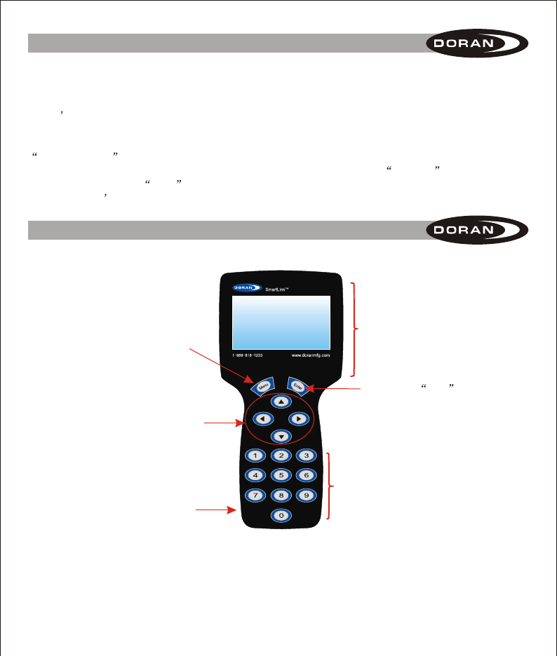
II. DESCRIPTION
Used to select a menu and to also
cancel out of a menu selection.
Information Screen for Data
Button to lock selected data
Arrow buttons used to navigate screen
for instructions and tire positions
On and Off Button
Numeric keypad to enter sensor
and trailer information to the tool.
2
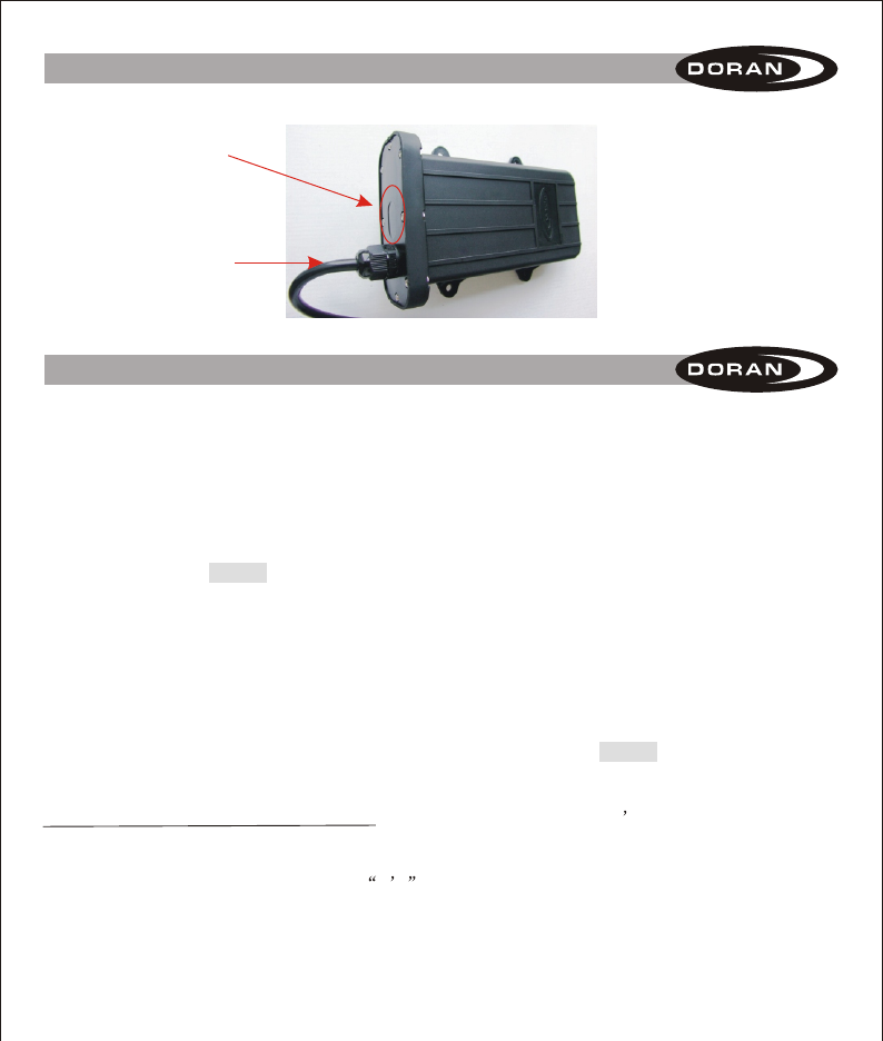
II. DESCRIPTION
Window where LED
lights can be seen
Power Cord
360SL Booster that tool will
program.
III. ENTERING DATA INTO THE TOOL
Specific data must be entered into the tool so the data can be transferred into the booster for
proper operation on the trailer. Entering data is as easy as sitting at your desk and inputting the
information for transfer to the Booster.
Turn on the SL tool using the button on the lower left side of the tool. The Doran Programming tool
welcome display will be shown.
When you press the MENU button you will have 6 selections to choose from:
READ INFORMATION FROM BOOSTER
SET BOOSTER ID
ADD SENSOR TO TRAILER
SEND INFORMATION TO BOOSTER
SELECT PRESSURE UNIT
VERSION INFORMATION
You can exit from any of these selections at any time by pressing the MENU button to return to the
main menu.
READ INFORMATION FROM BOOSTER: This function reads a booster s current information into
the SL (SmartLink) tool to make changes and resend, or as a shortcut for the programming of other
boosters by using the information downloaded. The SL tool will receive any SL booster signal if the
Trailer ID number in the tool is set at all 0 s . However, this method can be frustrating if there are
several SL boosters powered up in a close proximity to the SL tool.

III. ENTERING DATA INTO THE TOOL
The reason for this is that the tool will grab the first signal that it sees, and it may not be the one
that you are intending to work with. If there are not any trailers within a 50-foot radius you should
not have any trouble using the tool without setting the trailer ID number. If you know your trailer ID
number and have other active SL boosters in the area we suggest that you go to the
SET BOOSTER ID section and enter the Trailer ID number for the ease of reading the correct SL
booster. Power must be applied to the booster to use this feature.
1. Use the up and down arrow keys on the SL tool to select READ INFORMATION FROM
BOOSTER and press the ENTER button.
2. The SL tool will display READING . The SL tool must be within 6 feet of the booster to read
the information.
3. When the SL tool has read and downloaded the information, the screen will display
READ SUCCESS: along with the BOOSTER ID and TRAILER ID of the successfully read
information for your verification (see Figure 1). You can then press the MENU button to return to
the main menu.
4. If the READ SUCCESS: does not occur within 10 or 15 seconds, then the read may be failing
due to interference or the distance is too great. Position the tool closer to the booster and try
again. To terminate the READ function at anytime, press the MENU button.
SET BOOSTER ID: This is the next selection that can be made on the SL tool.
1. Use the up and down arrow buttons to select the SET BOOSTER ID.
2. Press the ENTER button to enter into this programming mode (see figure A).
3. Press the ENTER button, an arrow will be pointing to the Booster ID Number
and the first digit of the Booster ID number will begin to flash. If the Read
Information has been used successfully, the number shown will be the
Booster number read.
4. Enter the 9-digit booster ID number located on the cover of the booster using
the numbers on the tool s keypad.
READ SUCCESS:
001 065 198
TRAILER ID:
001 256
Figure 1
BOOSTER ID:
> 001 001 001
TRAILER ID:
136 987
Figure A
3
4
III. ENTERING DATA INTO THE TOOL
5. When you are sure the number that you input into the tool is correct you can press the ENTER
button to lock this number into the programming tool.
6. To select the Trailer ID number use the up and down arrow buttons to move the arrow to select
this and press the ENTER button. The first digit of the 6-digit trailer number will begin to flash.
Again, if a number is present it could be the number from a previous Read Information .
7. You can enter up to a 6 digit user defined number for the trailer ID by using the numbers on the
tool s keypad. This is provided so the driver can match the monitor s reference trailer number
to the numbers displayed on the trailer.
8. When you are sure the 6-digit number is correct, press the ENTER button to lock the number to
the tool. The right and left arrow keys allow making corrections.
9. Press the MENU button to return to the main menu.
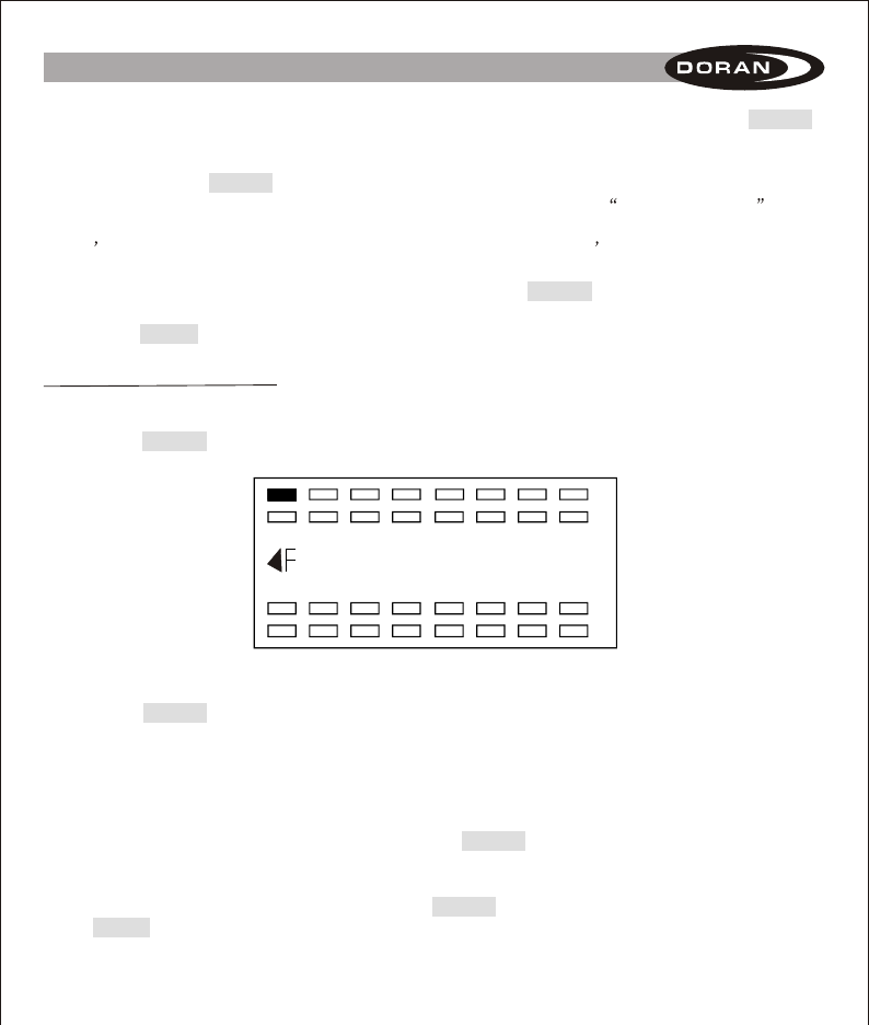
ADD SENSOR TO TRAILER: This mode allows the selection of which tire positions are to be used
for the booster and what sensor numbers will be assigned to them.
1. In the main menu use the arrow buttons to select ADD SENSOR TO TRAILER.
2. Press the ENTER button and the display will show all tire positions available for programming
(see Figure B).
3. Use the arrow buttons to select a wheel position where you want to program a sensor.
4. Press the ENTER button and the farthest left number of the sensor ID number will begin to flash.
If the READ INFORMATION FROM BOOSTER has been used, or the position has previously
been set, that ID number will be displayed. All programmed positions will be shown with solid /
shaded tire positions.
5. Using the numeric keypad you can change the number. When the sensor ID number has been
inputted the pressure number will begin to flash. The system is set at the factory for 100 psi.
If you do not need to change it, you can press the ENTER button to lock all information for that
wheel position.
6. Use the arrow buttons to select the next wheel position to program and repeat the steps above.
7. When all positions have been entered and the ENTER button was pressed for the last entry,
the MENU button can be pressed to return to the main menu.
000-000-000-000
Baseline: 100PSI
Figure B
5
III. ENTERING DATA INTO THE TOOL
SEND INFORMATION TO BOOSTER: This mode allows all information that was input or entered
into to the Programming Tool to be transferred to the Booster. The SmartLink Booster is the only
booster that can be programmed using the tool.
1. Be sure that the booster is powered and operating. Check to see if the red light is on in the
window next to the power cord attached to the booster.
2. The Programming Tool must be within 6 feet of the Booster for the transfer of information to be
successful because of the limited signal range.
3. Use the up and down arrow buttons to select SEND INFORMATION TO BOOSTER and press
the ENTER button.
4. The display will show SENDING . This signifies that the tool is transmitting the information.
5. When the transfer of information is complete, and the signals were accepted, the program tool
will display SET SUCCESS . This means the transfer of data was complete and successful.
VERSION INFORMATION: This menu item is to identify version status of the components. Doran
personnel may request this information when you are calling for assistance.
1. Use the up and down arrows keys to select VERSION INFORMATION and press the ENTER
button.
2. The screen will display the relevant version information.
SELECT PRESSURE UNIT: The factory default for the tool is PSI. The tool can be changed from
PSI to kPa or Bar as preferred.
1. Use the up and down arrow buttons to go to SELECT PRESSURE UNIT from the main menu.
2. Then you must press the ENTER button to enter this mode.
3. The display will show which pressure unit is the present default (see figure C).
4. Pressing the ENTER button will cause the Pressure Unit to begin to flash.
5. Pressing any of the arrow buttons will cause the Pressure Unit to change.
6. When you have selected the Pressure Unit that you desire press the ENTER
button to lock this unit into the memory.
7. Press the MENU button to return to the main menu.
Select
Pressure Unit
Current Pressure
Unit : PSI
Figure C
When this operation is completed the booster will now be ready to hookup to a tractor that is
equipped with the Doran 360SL system and will be ready to monitor the trailer tires as well as the
tractor tires that were programmed to the 360SL monitor.
Power Source: The power source for the Programming Tool comes from a replaceable 9-volt battery.
Remove the cover on the back of the tool and install a new battery when the original battery that
was included with the tool losses its power.

6
IV. LIMITED WARRANTY
ONE YEAR LIMITED WARRANTY: Subject to the limitations and exclusions set forth in this
Limited Warranty, the DORAN 360SL Program Tool is warranted against defects in material or
workmanship that result in a product failure under normal use during the one-year period following
the date of purchase by the original end-user. This Limited Warranty applies only to claims made
by the original end-user and cannot be assigned, transferred or conveyed to any subsequent
users. The exclusive remedy for any product determined by DORAN Mfg. LLC to be defective
within such period shall, at the sole option of DORAN Mfg. LLC, be the repair or replacement of
such defective product, or the refund of the purchase price therefore. No other remedy shall be
available.
EXCLUSIONS FROM COVERAGE: This Limited Warranty does not apply to any claims arising
from misuse, abuse, unauthorized repair or alteration, circumstances where the DORAN 360SL
Program Tool improperly wired contrary to the DORAN 360SL Program Tool product instructions;
or damage or defect attributable to fire or other casualty, including, without limitation, acts of God
or exposure to abrasive or corrosive materials or pollutants, or attributable to collision with other
objects, or the mishandling of the product.
LIMITATIONS: THIS LIMITED WARRANTY IS EXPRESSLY IN LIEU OF ALL OTHER EXPRESS
OR IMPLIED WARRANTIES, INCLUDING WITHOUT LIMITATION, THE IMPLIED WARRANTY
OF MERCHANTABILITY AND THE IMPLIED WARRANTY OF FITNESS FOR A PARTICULAR
PURPOSE, AND ALL OF ALL OTHER OBLIGATIONS OR LIABILITIES ON THE PART OF
DORAN MFG. LLC. THIS LIMITED WARRANTY SPECIFICALLY EXCLUDES ALL INCIDENTAL,
SPECIAL, OR CONSEQUENTIAL DAMAGES. IN NO EVENT, AND FOR NO CAUSE
WHATSOEVER, SHALL DORAN MFG. LLC HAVE ANY LIABILITY TO ANY PARTY IN EXCESS
OF THE ORIGINAL PURCHASE PRICE OF THE PRODUCT IN QUESTION.
EXCLUSIVE AGREEMENT: This Limited Warranty is a complete and exclusive statement of the
warranties which apply to the DORAN 360SL Program Tool. There are no express or implied
warranties beyond those expressly stated above. No employee, agent, dealer or other person is
authorized to give any warranties on behalf of DORAN Mfg. LLC, except as authorized in writing.
STATUTE OF LIMITATIONS In purchasing the DORAN 360SL Program Tool you agree that any
action for breach of contract or warranty must be commenced within one year after the cause of
action has accrued.

7
IV. LIMITED WARRANTY
PROCEDURE: Products determined to be defective within the terms of this Limited Warranty
should be returned to Doran Mfg. LLC, transportation prepaid. Call DORAN Mfg. LLC for return
authorization. No unauthorized returns shall be accepted. Sender is responsible for all costs
incurred in the removal or reinstallation and shipping of the returned product. A copy of the sales
slip from the point of purchase must accompany the returned product.
APPLICABLE LAW: The internal laws of the State of Ohio, U.S.A. shall govern this Limited
Warranty, and the exclusive venue for any dispute in connection with the purchase or use of the
product shall be the state and federal courts of general jurisdiction located in Hamilton County,
Ohio U.S.A.
SPECIAL NOTICE TO CONSUMERS: If you have purchased this product for person, family or
household use:
(1) Some states do not permit disclaimers or term limitations of implied warranties so that
the disclaimers and limitations in this Limited Warranty may not apply to you;
(2) Some states do not permit the exclusion or limitation of incidental or consequential
damages so that the exclusions and limitations in this Limited Warranty may not apply
to you; and
(3) This Limited Warranty gives you specific legal rights and you may have other rights that
vary from state to state.
For Warranty Return Authorization
Call Toll Free: 1-866-816-7233
FCC WARNING
This device complies with Part 15 of the FCC Rules. Operation is
subject to the following two conditions:
(1) this device may not cause harmful interference, and
(2) this device must accept any interference received, including interference that
may cause undesired operation.
NOTE: The manufacturer is not responsible for and radio or TV interference
caused by unauthorized modifications to this equipment. Such modifications could
void the user’s authority to operate the equipment.