DQ Technology M505 ADSL2+ 4 PORT WIRELESS MODEM W/USB User Manual
DQ Technology, Inc. ADSL2+ 4 PORT WIRELESS MODEM W/USB Users Manual
Contents
- 1. USERS MANUAL 1
- 2. USERS MANUAL 2
USERS MANUAL 1

M505
ADSL/2/2+ Wireless Four Port Ethernet/USB
Modem
User
抯
Manual

Manual Ver1.0
Table of Contents
1.INTRODUCTION.....................................................................................................................................................4
1.1 FEATURES.........................................................................................................................................................4
1.2 SYSTEM REQUIREMENTS ..................................................................................................................................4
2.INSTALLATION.......................................................................................................................................................5
FRONT PANEL................................................................................................................................................................5
REAR PANEL..................................................................................................................................................................6
CONNECTING THE HARDWARE .....................................................................................................................................6
Step 1. Connect the ADSL cable and optional telephone..........................................................................................6
Step 2. Connect the Ethernet cable............................................................................................................................6
Step 3. Attach the power connector...........................................................................................................................7
Step 4. Turn on the M505 and power up your systems..............................................................................................7
Step 5. Configure the M505 through the WEB interface...........................................................................................7
Step 6. Save the configurations and Reboot..............................................................................................................7
3.CONFIGURATION..................................................................................................................................................8
3.1 SETUP...............................................................................................................................................................8
3.2 ESTABLISH THE CONNECTION ..........................................................................................................................8
4.QUICK SETUP.......................................................................................................................................................10
4.1 PPP OVER ETHERNET (PPPOE)CONFIGURATION............................................................................................10
4.2 PPP OVER ATM(PPPOA)CONFIGURATION....................................................................................................13
4.3 MER(MACENCAPSULATION ROUTING)CONFIGURATION ............................................................................13
4.4 IPOA(IP OVER ATM)CONFIGURATION..........................................................................................................17
4.5 BRIDGING (TRANSPARENT/PASS-THROUGH MODEM)CONFIGURATION..........................................................20
5.ADVANCED SETUP..............................................................................................................................................23
5.1 WAN..............................................................................................................................................................23
5.2 LAN...............................................................................................................................................................24
5.3 NAT...............................................................................................................................................................25
5.4 ROUTING ........................................................................................................................................................28
5.5 SECURITY .......................................................................................................................................................31
5.6 DNS...............................................................................................................................................................34
5.7 DSL...............................................................................................................................................................36
- 2 -

Manual Ver1.0
5.8 PORT MAPPING...............................................................................................................................................37
5.9 INTERNET TIME ..............................................................................................................................................40
5.10 ACCESS CONTROL SERVICES ..........................................................................................................................40
5.11 IPSEC .............................................................................................................................................................43
5.12 CERTIFICATE...................................................................................................................................................44
6. WIRELESS SETUP ..........................................................................................................................................47
6.1 BASICS ...........................................................................................................................................................50
6.2 SECURITY .......................................................................................................................................................50
6.3 MACFILTER ..................................................................................................................................................55
6.4 WIRELESS BRIDGE..........................................................................................................................................55
6.5 ADVANCED .....................................................................................................................................................56
6.6 STATION INFO .................................................................................................................................................58
7. MANAGEMENT UTILITIES.............................................................................................................................60
7.1 BACKUP SETTINGS .........................................................................................................................................60
7.2 UPDATE SETTINGS ..........................................................................................................................................62
7.3 RESTORE SETTINGS ........................................................................................................................................62
7.4 UPDATE FIRMWARE ........................................................................................................................................63
7.5 TR-069CLIENT ..............................................................................................................................................64
7.6 SAVE/REBOOT ................................................................................................................................................64
7.7 SYSTEM LOG ..................................................................................................................................................67
8.CONNECTION STATUS.......................................................................................................................................67
8.1 LAN...............................................................................................................................................................67
8.2 WAN..............................................................................................................................................................67
8.3 ATM...............................................................................................................................................................69
8.4 ADSL.............................................................................................................................................................69
8.5 ROUTE............................................................................................................................................................70
8.6 ARP...............................................................................................................................................................71
8.7 DHCP............................................................................................................................................................71
8.8 SUMMARY ......................................................................................................................................................72
9.DIAGNOSTICS AND HELP..................................................................................................................................73
10.APPENDIX A ?SPECIFICATIONS.....................................................................................................................74
11.APPENDIX B ?WARRANTIES............................................................................................................................76
12.APPENDIX C ?REGULATIONS.........................................................................................................................77
- 3 -

Manual Ver1.0
1. Introduction
Congratulations on becoming the owner of the Master series of ADSL2+ modem routers. You
will now be able to access the Internet using your high-speed ADSL/2+ connection. The
Master series of ADSL2+ modems has the following major features.
Features
ADSL/2/2+ modem for high speed Internet access
Network Address Translation (NAT) and IP filtering functions to provide
network sharing and firewall protection for your computers
Easy configuration via a web browser
SPI firewall to protect you from outside intruders and attacks
TR-069 compliant for automatic modem update through your high speed
Internet access
This User抯 Manual will guide you through the installation and configuration of your M505
modem.
System Requirements
Before installing your M505 modem, make sure that you have the following:
ADSL service up and running on your telephone line, with at least one public Internet
address for your LAN
Computer containing an Ethernet 10Base-T/100Base-T network interface card (NIC)
Computer containing a USB port (M505 modems)
For system configuration, use the web-based (HTTP) user interface.
Note: Make sure that your computer has a web browser such as Internet Explorer v5.0 or
later, or Netscape v4.7 or later.
- 4 -

Manual Ver1.0
2. Installation
In addition to this document, your M505 should arrive with the following:
One power adapter and power cord
One Ethernet cable with RJ-45 connector
One USB A-B cable
One Telephone cable with RJ-11 connector
揤isionnet DSL?CD
Front Panel
The front panel LEDs indicates the status of the unit. (Left to Right)
M505
Label Color Function
Wireless Green Green ?Wireless is activated on modem
Flashing Green ?Wireless activity is present
Off - Modem off or no radio signal detected
USB Green Off - Power Off ?or ?No Device Detected
Solid Green ?Device connected including wake on LAN
Flashing Green ?LAN activity present for that port
Ethernet 1-4 Green Off - Power Off ?or ?No Device Detected on any LAN
port
Solid Green ?Device connected including wake on LAN
on any LAN port
Flashing Green ?LAN activity present
Internet Green Solid Green ?IP connected ?no traffic passing
Device has a public IP via either static/ DHCP/
or IPCP If PPP is used it has been authenticated
If IP or PPPOE session is idle and dropped,
light to remain green as long as ADSL is still
present. Light to turn red if upon attempting
new session it fails.
Off ?Modem Power Off.
LED Should remain off if modem is in bridged
mode
DSL Green Green ?DSL Good Sync
Off - Powered off
Flashing Green - DSL Attempting sync
Power Green On ?Solid Green
Off ?The Modem is Off
Red ?Power on self test/ Device Malfunction (not
bootable) and device malfunction
- 5 -
Manual Ver1.0
Malfunction is any state which would prevent
syncing or passing of data
Rear Panel
The connectors located at the rear panel have the following functions.
M505
Interface Function
Switch(Push Button) Power switch on/off
Power Connects to the power adapter cable
Reset Resets unit抯 configuration to factory default
USB USB connection: Connects to your PC抯 USB 1.1/2.0
port
Ethernet 1-4 RJ-45 connector: Connects to your PC's Ethernet port,
or to the uplink port on your LAN's hub/switch
Line RJ-11 connector: Connects to your ADSL line
Connecting the Hardware
Connect the M505 to the phone jack, the power outlet, and your computer or network.
WARNING
Before you begin, turn the power off for all devices. These include your
computer(s), your LAN hub/switch (if applicable), and the M505.
Step 1. Connect the ADSL cable and optional telephone
Connect one end of the phone cable to the RJ-11 connector on the rear panel of the M505. Connect
the other end to the ADSL outlet provided by your service provider (normally MODEM port of the
included splitter).
Step 2. Connect the Ethernet cable
Connect one end of the Ethernet cable to the RJ-45 connectors on the rear panel of the M505 and
connect the other end to your PC抯 network adaptor (NIC). If you are connecting a LAN to the
Master series, attach one end of the Ethernet cable to a regular hub port and the other end to the
LAN port on the M505.
- 6 -

Manual Ver1.0
Step 3. Attach the power connector
Connect the AC power adapter to the power connector on the M505 and plug in the adapter to a
wall outlet or power extension.
Step 4. Turn on the M505 and power up your systems
Press the Power switch on the back panel of the M505 to the ON position.
Boot up your computer(s) and any LAN devices such as hubs or switches.
Step 5. Configure the M505 through the WEB interface
Please refer to Chapter 3.
Step 6. Save the configurations and Reboot
Save the changes you made on the M505 and it will automatically reboot to make the settings
permanent.
- 7 -
Manual Ver1.0
3. Configuration
3.1 - Setup
Connect your M505 and PC with an RJ-45 Ethernet cable.
Turn on the M505.
The default IP address of M505 is 192.168.1.254.
3.2 - Establish the Connection
Enter the IP address (default: 192.168.1.254) of M505 in the address line of your
web browser.
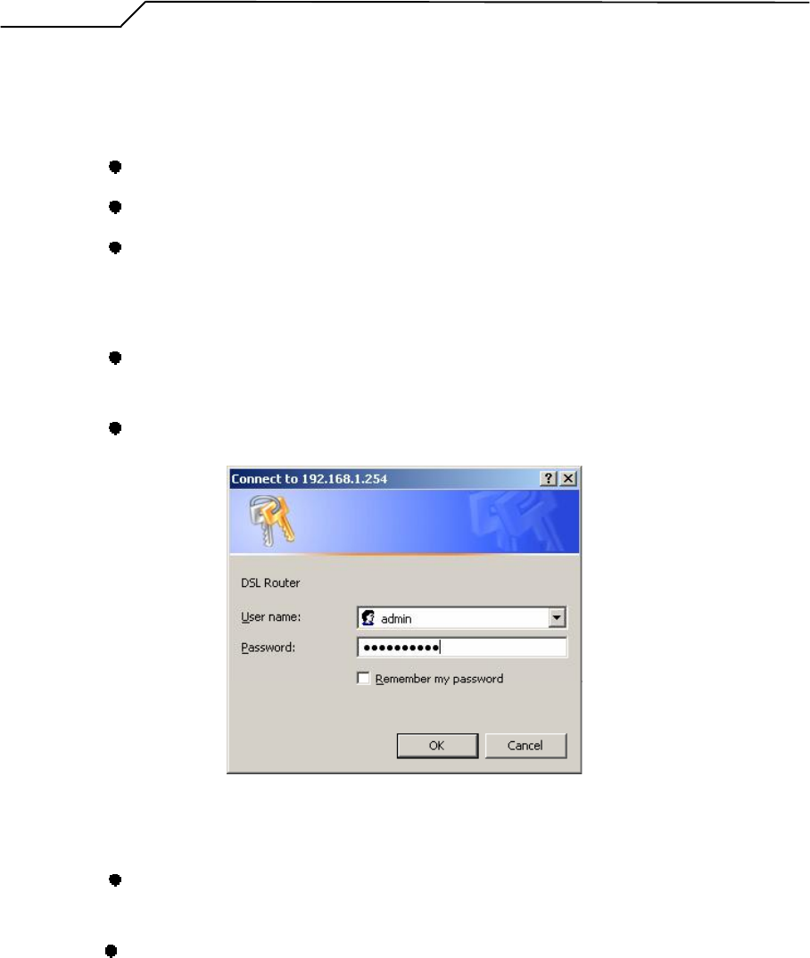
A Dialogue Box will pop up to request the user to login. (Figure 1)
Figure 1. Login dialogue box
Please enter the management username/password into the fields then click on the
OK button (default username/password is: admin /0123456789).
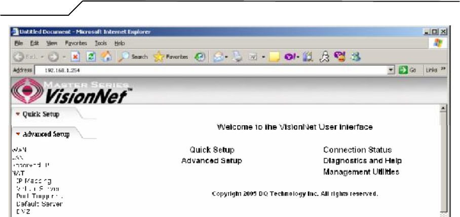
If the authentication is valid, the main page will be displayed on the screen.
(Figure 2)
- 8 -
Manual Ver1.0
Figure 2. M505 Home Page
- 9 -

Manual Ver1.0
4. Quick Setup
The system administrator can configure the M505 remotely or locally via a Web
Browser. Network configuration needs to be planned and decided before starting the
configuration procedure.
Quick Setup allows system administrator to select the appropriate operation mode and
configure the corresponding settings step by step to create a connection. The following
operation modes are supported under Quick Setup:
PPP over Ethernet (PPPoE)
PPP over ATM (PPPoA)
MER (MAC Encapsulation Routing)
IPoA (IP over ATM)
Bridging
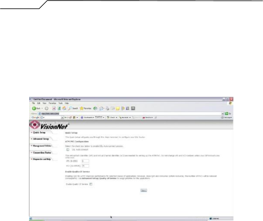
4.1 - PPP over Ethernet (PPPoE) Configuration
Click on 換uick Setup?in the left frame and follow the steps below to create a PPP
over Ethernet (PPPoE) connection.
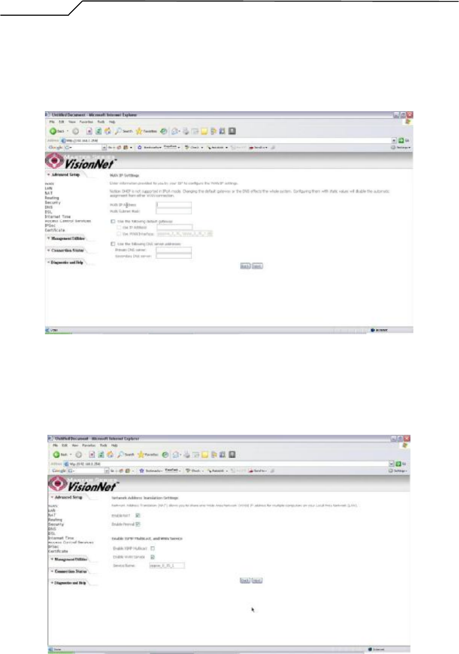
Here you can either select DSL Autoconnect (Modem will attempt to find the correct
VPI/VCI settings) or Uncheck the box to manually input the VPI/VCI settings.
Figure 3. Quick Setup ?ATM PVC
- 10 -
Manual Ver1.0
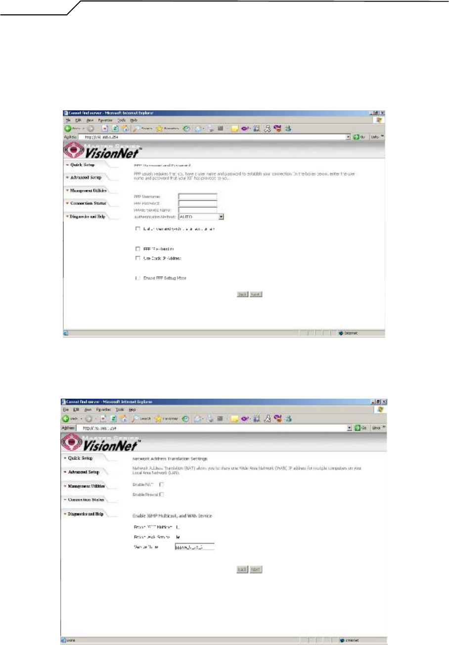
PPP Username and Password
This page is where you will enter the 揚PP Username? and 揚PP Password?
Please contact you ISP for this information.
Figure 4. Quick Setup ?Username, Password and option forIP extension and Static IP
WAN Setup ?NAT and IGMP
Figure 5. Quick Setup ?WAN Setup ?NAT, IGMP, and Firewall
- 11 -
Manual Ver1.0
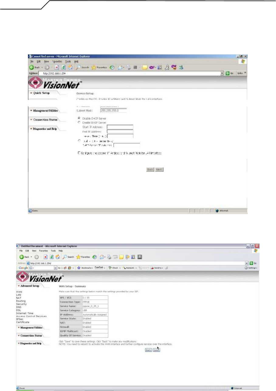
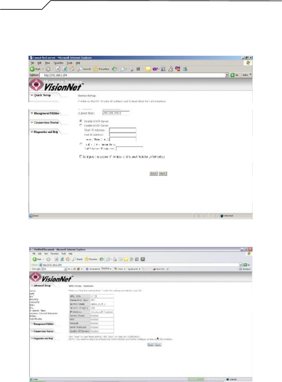
Device Setup
This page is where you can configure the modem抯 IP address and Default DHCP
server range. Default is 192.168.1.254
Figure 6. Quick Setup ?Device Setup ?LAN and DHCP Server
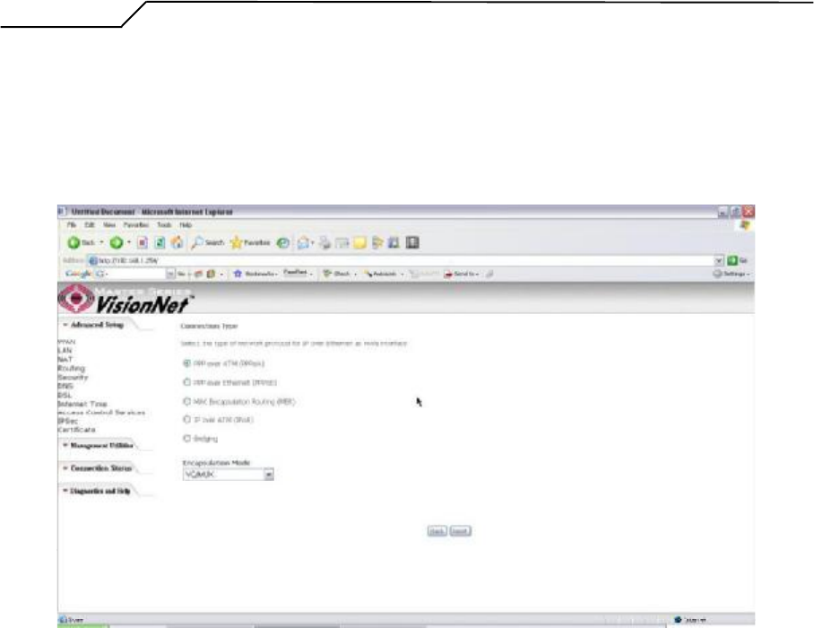
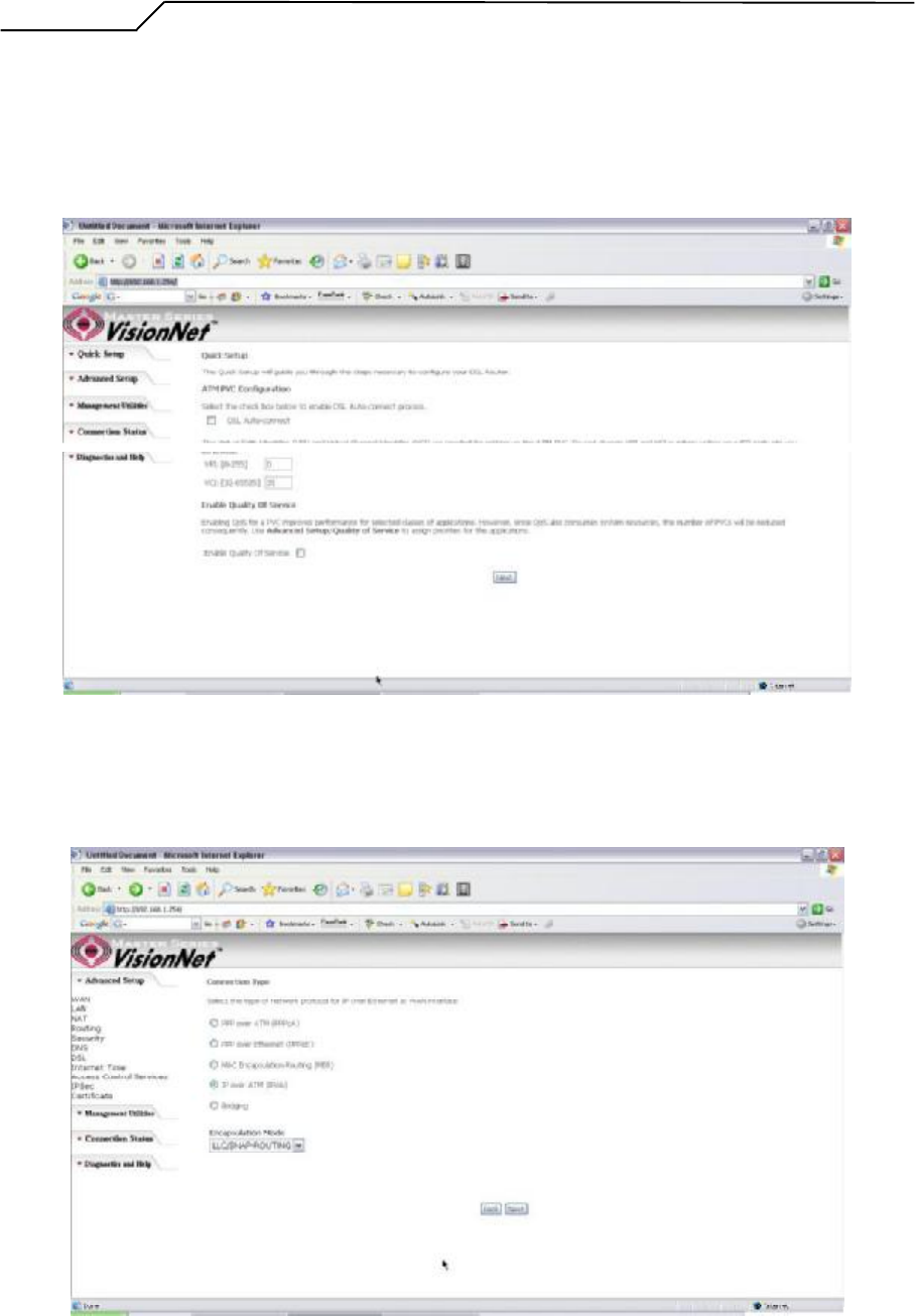
Summary
Figure 7. Quick Setup ?WAN Setup ?Summary
- 12 -
Manual Ver1.0
The last page displays a summary of your settings. Click on the 揝ave/Reboot?
button to complete the configuration.
4.2 - PPP over ATM (PPPoA) Configuration
Configuration of PPPoA is similar to PPPoE. Select 揚PP over ATM (PPPoA)?in
揅onnection Type? Please refer to PPPoE settings (Section 4.1) for details.
Figure 8. Quick Setup ?Connection Type (PPPoA)
4.3 - MER (MAC Encapsulation Routing) Configuration
Click on 換uick Setup?in the left frame and follow the steps below to create a MER
connection.
Here you can either select DSL Autoconnect (Modem will attempt to find the correct
VPI/VCI settings) or Uncheck the box to manually input the VPI/VCI settings.
- 13 -
Manual Ver1.0
Figure 9. Quick Setup ?ATM PVC Configuration (MER)
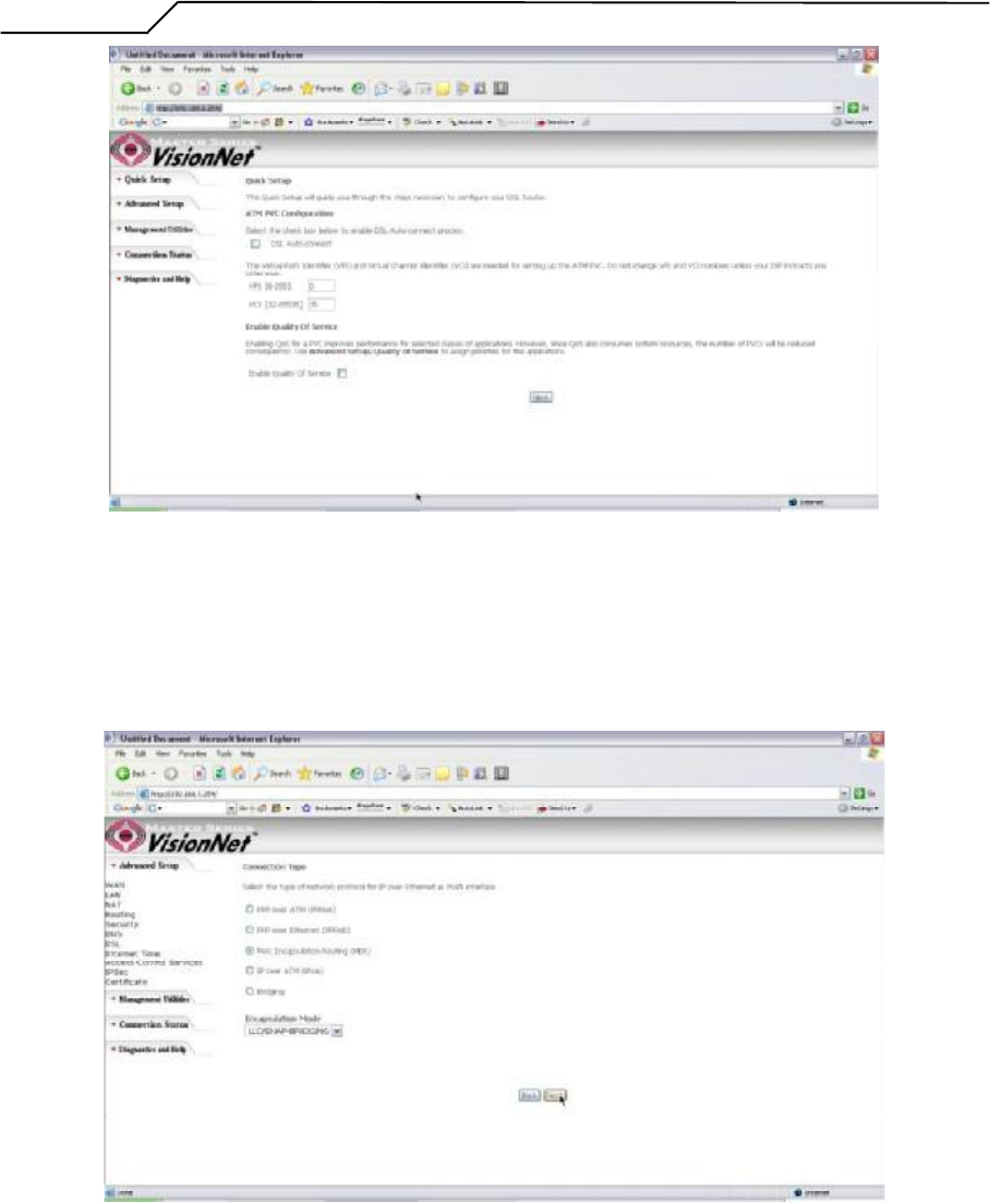
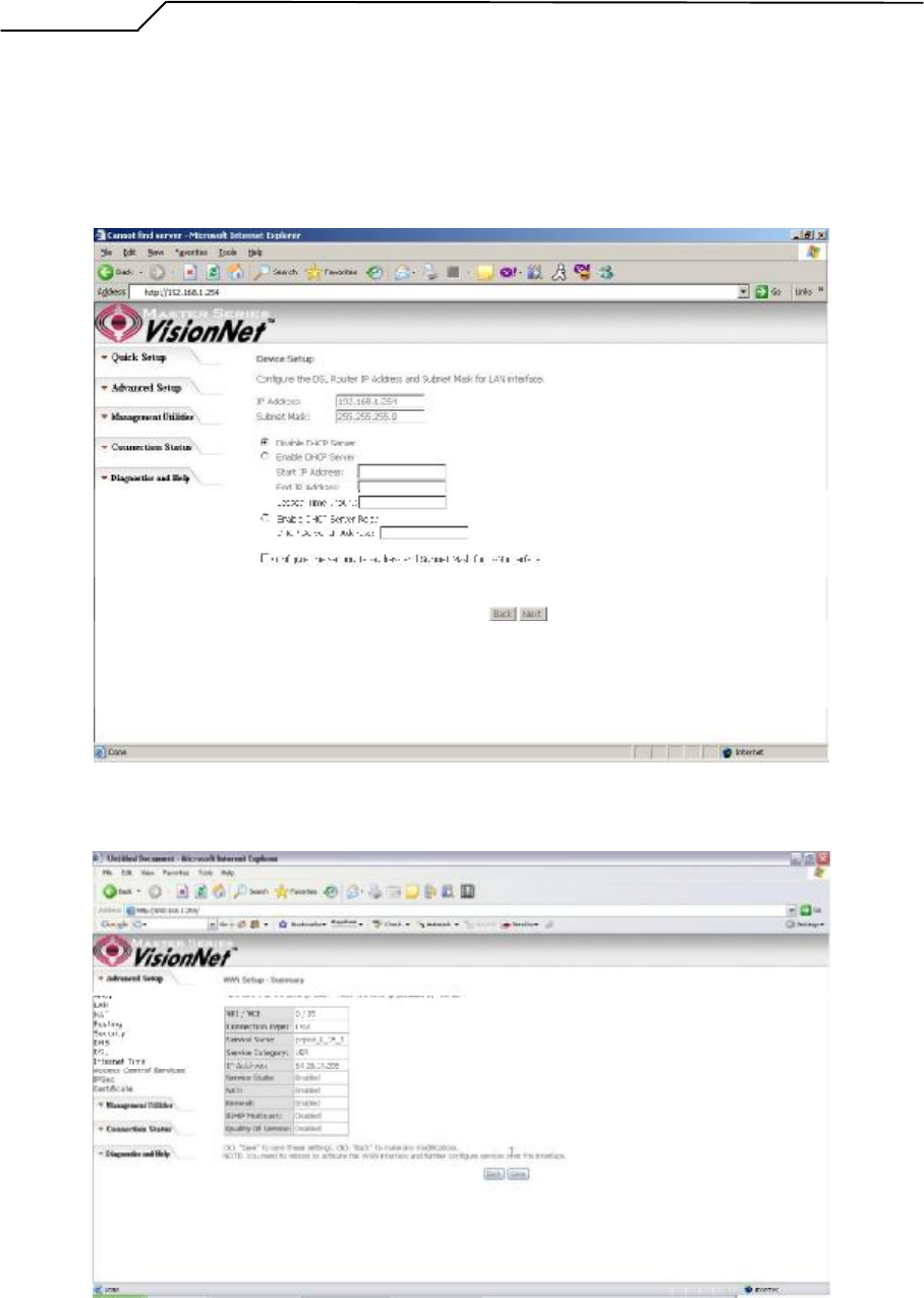
Quick Setup ?Connection Type
This page is where you select MER (MAC Encapsulation Routing).
Figure 10. Quick Setup ?Connection Type
Quick Setup ?WAN IP Settings
This page is where you either select for the M505 to obtain the IP information
automatically (sometime referred to as DHCP connection) or you can input the IP
- 14 -
Manual Ver1.0
address if Static IP抯 were assigned by your Internet Service Provider.
Figure 11. Quick Setup ?WAN IP Settings
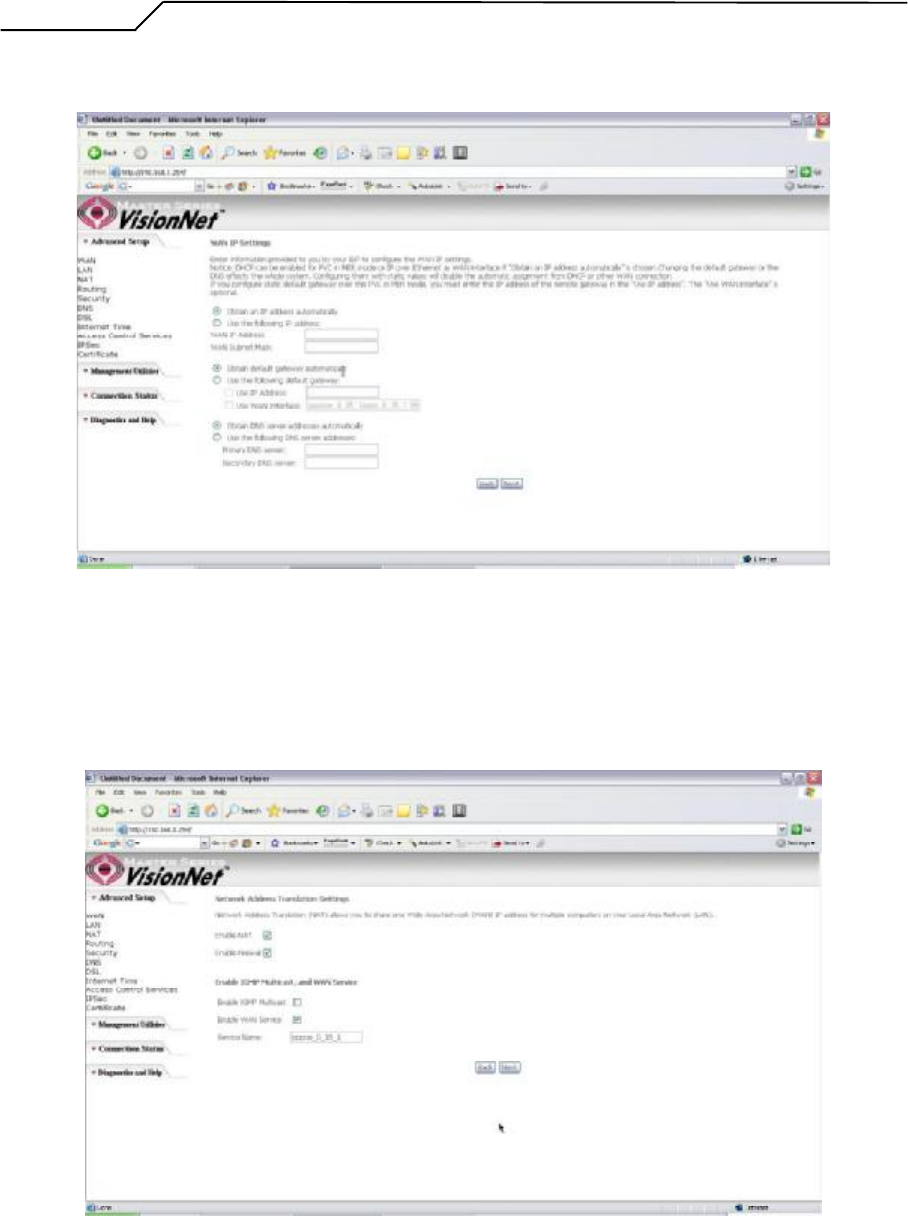
Quick Setup ?Network Address Translation and IGMP
This page is where you either select to enable NAT (Please enable this option for the
M511 to route private (Local) IP address to your LAN clients).
Figure 12. Quick Setup ?Network Address Translation and IGMP
- 15 -
Manual Ver1.0
Quick Setup - Device Setup
This page is where you can configure the modem抯 IP address and Default DHCP
server range. Default is 192.168.1.254
Figure 13. Quick Setup ?Device Setup ?LAN and DHCP Server
Quick Setup - Summary
Figure 14. Quick Setup ?WAN Setup ?Summary
The last page displays a summary of your settings. You must click on the 揝ave?button to complete
the configuration.
- 16 -
Manual Ver1.0
4.4 - IP over ATM (IPoA) Configuration
Click on 換uick Setup?in the left frame and follow the steps below to create an IPoA
connection.
Here you can either select DSL Autoconnect (Modem will attempt to find the correct
VPI/VCI settings) or Uncheck the box to manually input the VPI/VCI settings.
Figure 15. Quick Setup ?ATM PVC
Quick Setup ?Connection Type
This page is where you select IPoA (IP over ATM).
Figure 16. Quick Setup ?Connection Type
- 17 -
Manual Ver1.0
Quick Setup ?WAN IP Settings
This page is where you input the IP information provided by your ISP. This
connection does not support DHCP (Where modem obtains IP information
automatically)
Figure 17. Quick Setup ?WAN IP Settings
Quick Setup ?Network Address Translation and IGMP
This page is where you either select to enable NAT (Please enable this option for the
M505 to route private (Local) IP address to your LAN clients).
- 18 -
Manual Ver1.0
Figure 18. Quick Setup ?Network Address Translation and IGMP
Quick Setup - Device Setup
This page is where you can configure the modem抯 IP address and Default DHCP
server range. Default is 192.168.1.254
Figure 19. Quick Setup ?Device Setup ?LAN and DHCP Server
Quick Setup ?Summary
Figure 20. Quick Setup ?WAN Setup ?Summary
- 19 -
Manual Ver1.0
The last page displays a summary of your settings. Click on the 揝ave?button to complete the
configuration.
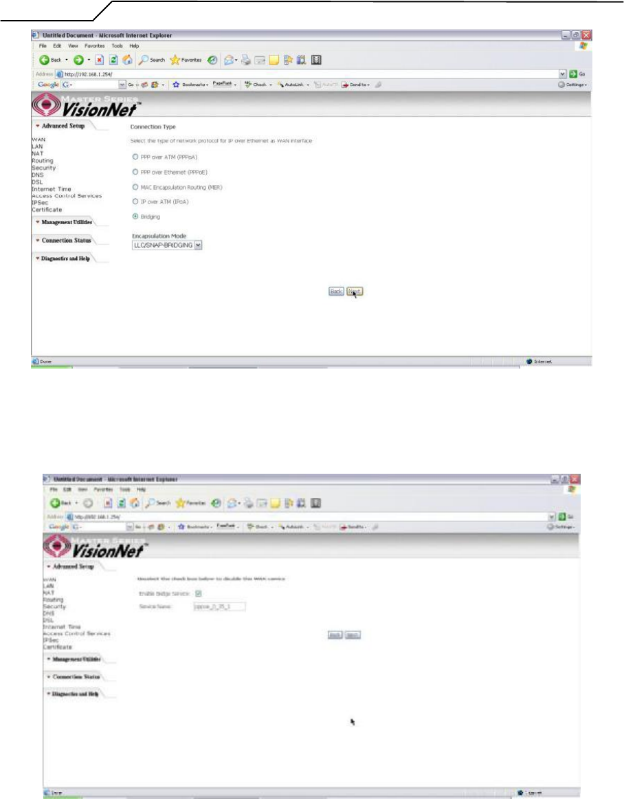
4.5 - Bridging (Transparent/Pass-through) Configuration
Click on 換uick Setup?in the left frame and follow the steps below to create a Bridge
connection.
Here you can either select DSL Autoconnect (Modem will attempt to find the correct
VPI/VCI settings) or Uncheck the box to manually input the VPI/VCI settings.
Figure 21. Quick Setup ?ATM PVC Configuration
Quick Setup ?Connection Type
This page is where you select Bridging (Last option).
- 20 -
Manual Ver1.0
Figure 22. Quick Setup ?Connection Type
Quick Setup ?Enabling Bridge Mode
For this page, please check the box 揈nabled Bridge Service?and click 揘ext?
Figure 23. Quick Setup ?Enabling Bridge Mode
- 21 -
Manual Ver1.0
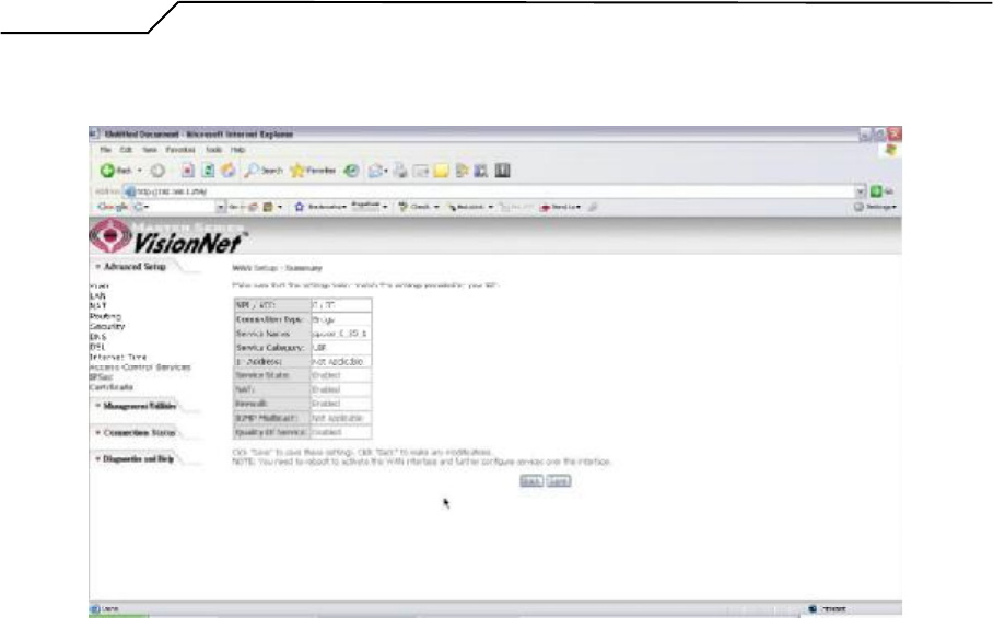
Quick Setup ?Summary
Figure 24. Quick Setup ?WAN Setup ?Summary
The last page displays a summary of your settings. Please click the 揝ave?button to complete the
configuration process.
- 22 -

Manual Ver1.0
5. Advanced Setup
Advanced Setup allows system administrator to configure the following topics:
WAN
LAN
NAT
Routing
Security
DNS
DSL
Port Mapping
Internet Time
Access Control Services
IPSec
Certificates
5.1 - WAN
- 23 -
Manual Ver1.0
Figure 25. Advanced Setup ?WAN
This page shows the current existing WAN interfaces in the system. User can choose
to Add,Edit, or Remove WAN interfaces. Clicking the 揂dd?button will take the user
to a wizard similar to the Quick Setup (Chapter 4) wizard, where additional WAN
protocols can be configured.
Protocols supported:
PPPoE, PPPoA, IP over ATM (IPoA), Bridging, MAC Encapsulation Routing
(MER).
Please refer to Section 4 for additional information regarding creating WAN
Connections.
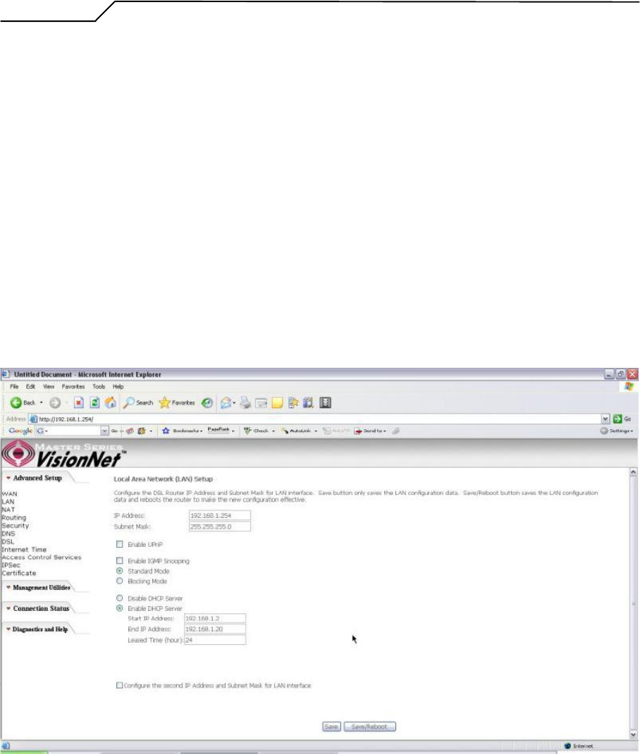
5.2 - LAN
Figure 26. LAN Setup page
Input the IP Address and Subnet Mask of your M505. (Default: 192.168.1.254)
Check the box if you want to enable UPnP and/or IGMP Snooping.
Disable/Enable DHCP Server, and change the starting and ending IP address of your
server pool if needed.
Check the 揅onfigure the second IP Address and Subnet Mask for LAN interface?if a
- 24 -
Manual Ver1.0
second IP address is used.
5.3 - NAT
Three functions are supported in NAT: Virtual Servers, Port Triggering, and DMZ Host.
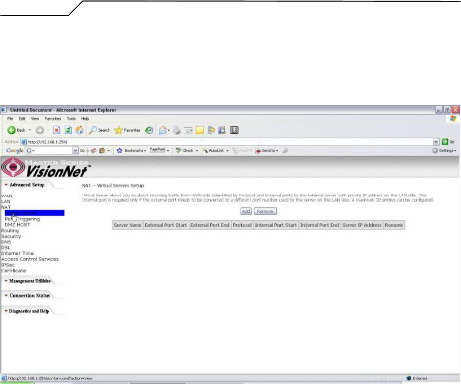
Virtual Servers
Figure 27. Advanced Setup ?NAT
Virtual Server allows you to direct incoming traffic from WAN side (identified by Protocol
and External port) to the Internal server with private IP address on the LAN side. The
Internal port is required only if the external port needs to be converted to a different port
number used by the server on the LAN side. A maximum of 32 entries can be configured.
Click on 揂dd?to enter configuration page to add your own rule(s). Some common used
servers (Web, FTP, Mail, 卐tc.) are already pre-defined for the M505. User can simply
select the desired server from the pull-down menu and assign the IP address of the local
PC.
To delete the configured rule(s), check the 揜emove?box of the specific rule(s) and click
on 揜emove?
- 25 -
Manual Ver1.0
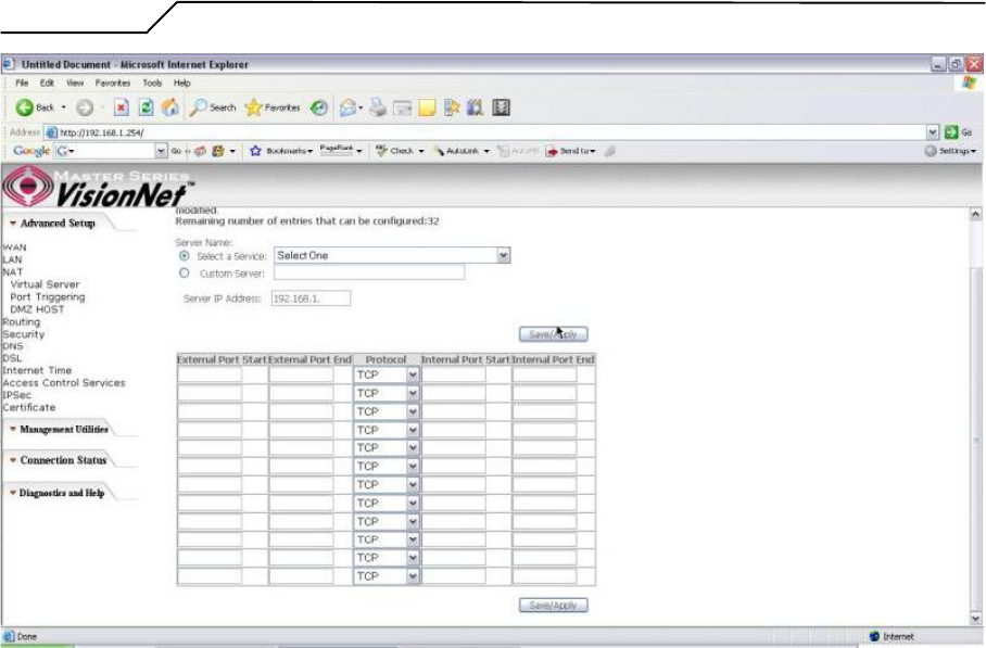
Figure 28. Advanced Setup ?NAT ?Virtual Servers
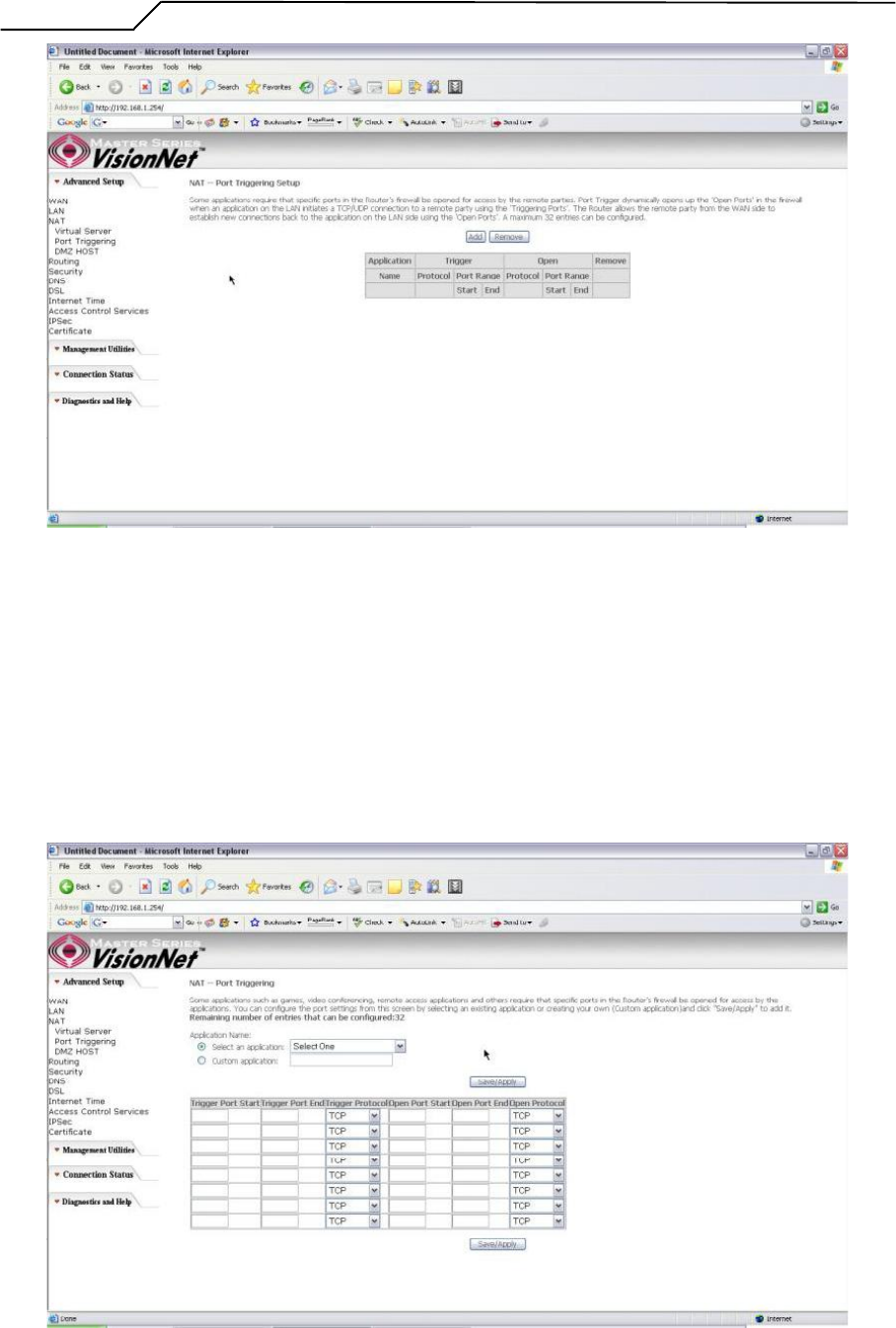
Port Triggering
Some applications require that specific ports in the Router's firewall be opened for access
by the remote parties. Port Trigger dynamically opens up the 揙pen Ports?in the firewall
when an application on the LAN initiates a TCP/UDP connection to a remote party using
the 揟riggering Ports? The Router allows the remote party from the WAN side to establish
new connections back to the application on the LAN side using the 揙pen Ports? A
maximum of 32 entries can be configured.
- 26 -
Manual Ver1.0
Figure 29. Advanced Setup ?NAT ?Port Triggering
Click on 揂dd?to enter the configuration page to add your own rule(s). Some games,
video conferencing, remote access applications and other software might require that
specific ports in the Router's firewall be opened for access. You can configure the port
settings from this screen by selecting an existing application or creating your own (Custom
application) and click 揝ave/Apply?to add it.
To delete the configured rule(s), check the 揜emove?box of the specific rule(s) and click
on 揜emove?
- 27 -
Manual Ver1.0
Figure 30. Advanced Setup ?NAT ?Add Port Triggering
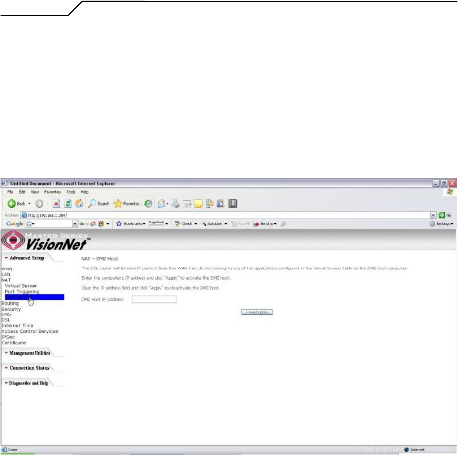
DMZ Host
The DSL router will forward IP packets from the WAN that do not belong to any of the
applications configured in the Virtual Servers table to the DMZ host computer.
Enter the computer's IP address and click 揝ave/Apply?to activate the DMZ host.
Clear the IP address field and click 揝ave/Apply?to deactivate the DMZ host.
Figure 31. Advanced Setup ?NAT ?DMZ Host
5.4 - Routing
There are three routing related settings:
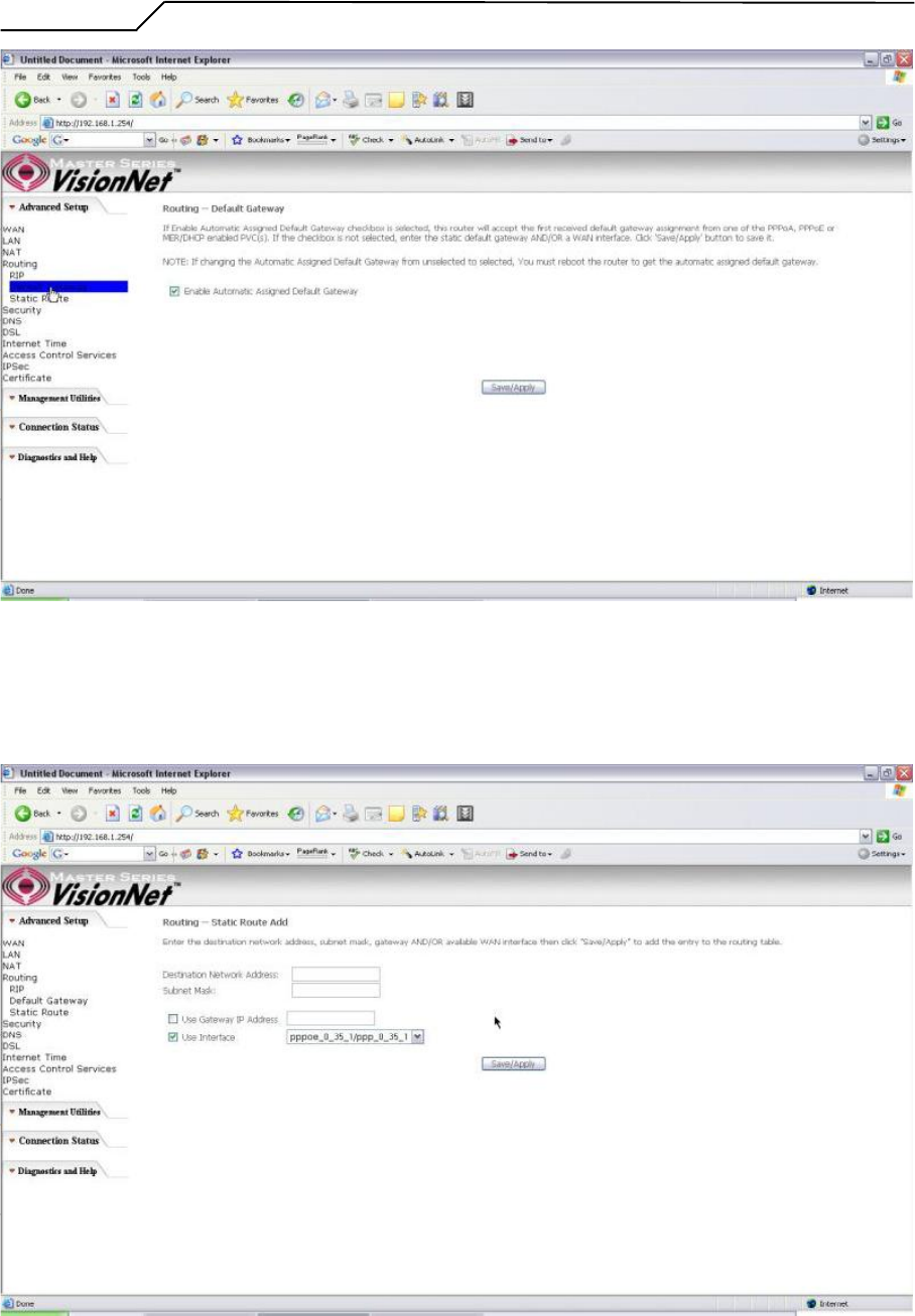
Routing ?Default Gateway
If the 揈nable Automatic Assigned Default Gateway?checkbox is selected, the M505 will
accept the first received default gateway assignment from one of the PPPoA, PPPoE or
MER/DHCP enabled PVC(s). If the checkbox is not selected, enter the static default
gateway AND/OR a WAN interface. Click the 揝ave/Apply?button to save it.
NOTE: If changing the 揈nable Automatic Assigned Default Gateway?from
unselected to selected, you must reboot your M505 to activate the automatically
assigned default gateway.
- 28 -
Manual Ver1.0
Figure 32. Advanced Setup ?Routing ?Default Gateway
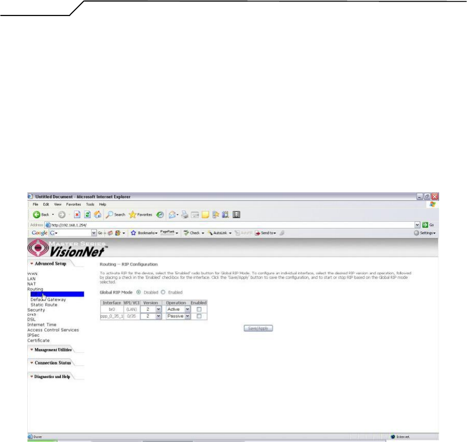
Routing ?Static Route
Click on 揂dd?to create a new Static Route. Up to 32 entries can be configured.
- 29 -
Manual Ver1.0
Figure 33. Advanced Setup ?Routing ?Add New Static Route
Enter the destination network address, subnet mask, gateway AND/OR available WAN
interface, then click 揝ave/Apply?to add the entry to the routing table.
Routing ?RIP
The Routing Information Protocol (RIP) is designed for exchanging routing information
within a small to medium-size network.
Figure 34. Advanced Setup ?Routing ?RIP
To configure an individual interface, select the desired RIP version and operation:
RIP Version 1: Class-based IP network.
RIP Version2: Classless IP network.
Operation Active: Broadcast and listen to other RIP enabled devices.
OperationPassive: Listen only.
Place a check in the 揈nabled?checkbox next to the interface to complete the
configuration. Click the 揝ave/Apply?button to save the configuration. To start/stop RIP
for the M505, select the 揈nabled/Disabled?radio button for Global RIP Mode?
- 30 -
Manual Ver1.0
5.5 - Security
Two functions are supported in Firewall: Outgoing IP Filtering and MAC Filtering.
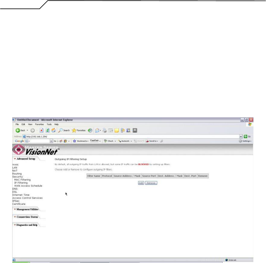
Firewall ?Outgoing IP Filtering
By default, all outgoing IP traffic from LAN is allowed, but some IP traffic can be
BLOCKED by setting up filters. Choose 揂dd?to configure outgoing IP filters. To remove,
check the item and click 揜emove?
Figure 35. Advanced Setup ?Security ?Outgoing IP Filtering Setup
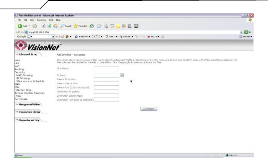
The screen allows you to create a filter rule to identify outgoing IP traffic by specifying a
filter name and at least one of the conditions below. All of the specified conditions in this
filter rule must be satisfied for the rule to take effect. Click 揝ave/Apply?to save and
activate the filter.
- 31 -
Manual Ver1.0
Figure 36. Advanced Setup ?Security ?Add new Outgoing IP Filter
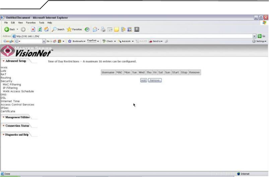
Security ?WAN Access Control
WAN Access Control allows users to create time of day restrictions to a specific LAN
device connected to the Router. Click 揂dd?to configure restriction rules. To remove,
check the item and click 揜emove? Up to 16 entries can be configured and used.
- 32 -
Manual Ver1.0
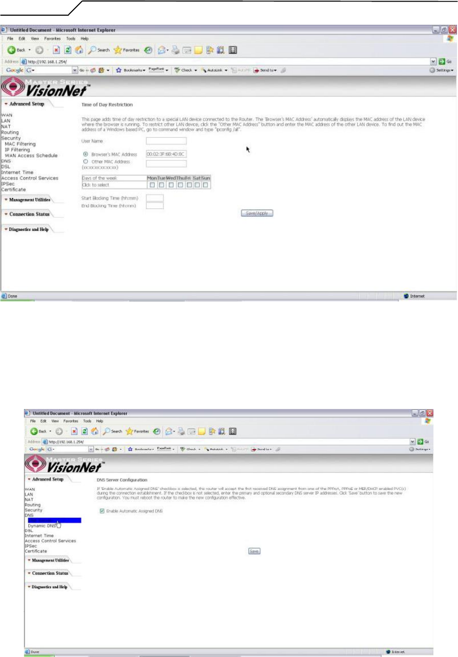
Figure 37. Advanced Setup ?Security ?WAN Access Control
The MAC Address of the current 揵rowser?will automatically display on the 揃rowser抯
MAC Address?box. To restrict another LAN device, click the 揙ther MAC Address?
button and enter the MAC address of that LAN device.
To find out the MAC address of a Windows-based PC, go to the command prompt window
and type 搃pconfig /all? Click 揝ave/Apply to save and activate the restriction rule.
- 33 -
Manual Ver1.0
Figure 38. Advanced Setup ?Security ?Add new Parental Control restriction
5.6 - DNS
DNS Server
- 34 -
Manual Ver1.0
Figure 39. Advanced Setup ?DNS Server
If 揈nable Automatic Assigned DNS?checkbox is selected, the M505 will accept the first
received DNS assignment from one of the PPPoA, PPPoE or MER/DHCP enabled PVC(s)
during the connection establishment. If the checkbox is not selected, enter the primary and
optional secondary DNS server IP addresses. Click the 揝ave?button to save it.
NOTE: If changing from unselected 揈nable Automatic Assigned DNS?to selected, you
must reboot the M505 to get the automatic assigned DNS addresses.
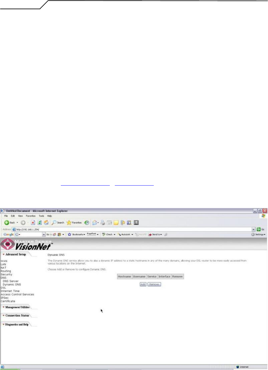
Dynamic DNS
The Dynamic DNS service allows you to give a dynamic IP address a static hostname in
any of the domains. This function allows your M505 to be more easily accessible from
various locations of the Internet.
Choose 揂dd?to configure Dynamic DNS.
Before you proceed, please visit one of these two websites to receive your own Dynamic
DNS service: www.dyndns.org or www.tzo.com.
To remove, check the item and click 揜emove?
Figure 40. Advanced Setup ?DNS ?Dynamic DNS
- 35 -
Manual Ver1.0
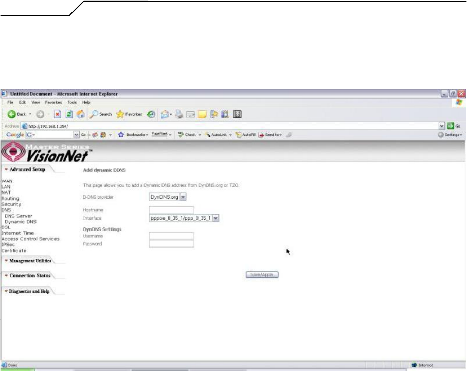
Select your Dynamic DNS service provider from 慏-DNS provider? and enter your
registration information. Click 揝ave/Apply?to save the configuration.
Figure 41. Advanced Setup ?DNS ?Add Dynamic DNS
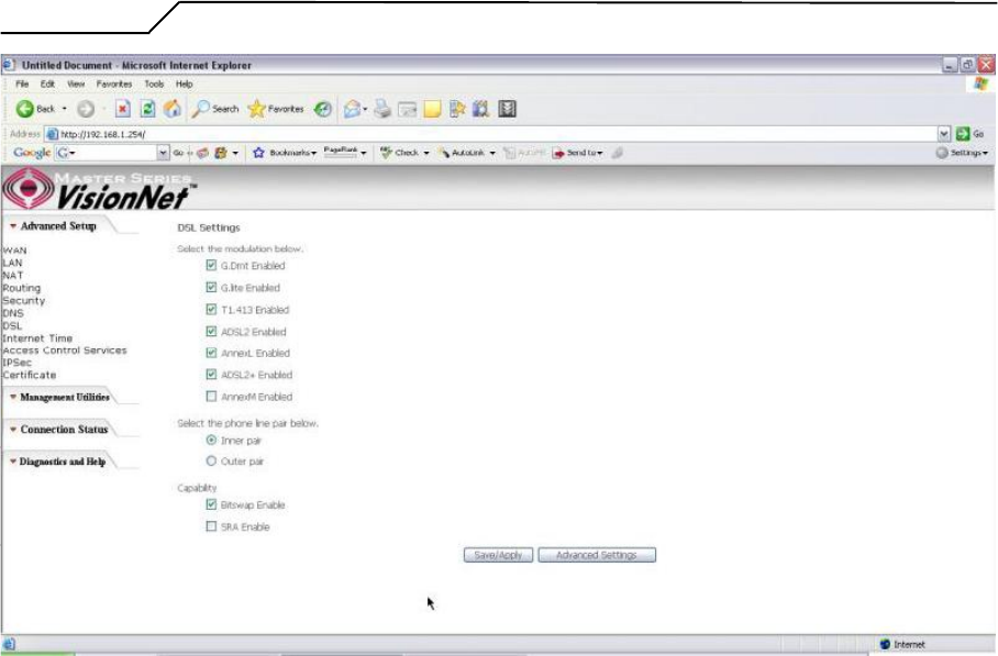
5.7 - DSL
This page allows you to choose which handshake protocols you want your M505 to look
through when training. Uncheck any of the listed protocols that have 揈nabled?at the end
of it to have the modem skip that protocol when synchronizing with your ADSL line.
Leave it checked if you would like the modem to cycle through those settings.
- 36 -
Manual Ver1.0
Figure 42. Advanced Setup ?DSL Settings
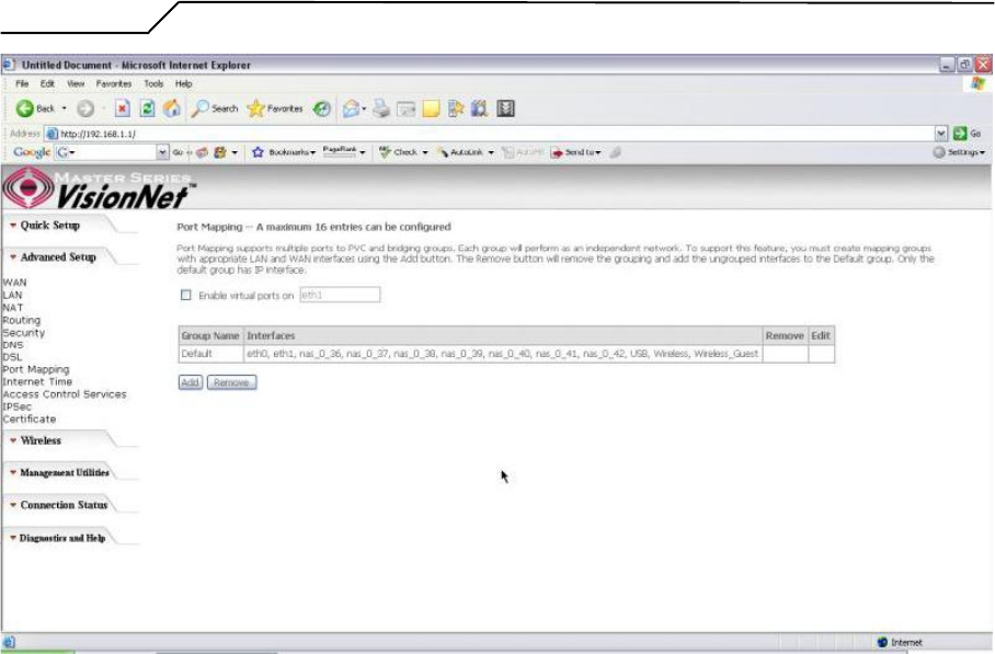
5.8 ?Port Mapping
Use this page to set up Port Mapping and Virtual Port groups. These are used when
ISPs or Telcos are running different PVCs (or connection profiles) on the same DSL
line. This is commonly used when receiving MPEG1/2 video steams and Internet
at the same time. VLAN groups allow you to hook up a PC on one or more Ethernet
ports of the router for broadband Internet and connect an IP set top box to the other
ports to watch TV on the same line simultaneously.
By default all LAN ports and wireless will be grouped and mapped to one WAN
interface.
To enable virtual ports on the physical LAN ports, check the 揈nable virtual ports
on:?checkbox and click on the Add button to create a new mapping group.
- 37 -
Manual Ver1.0
Figure 43. Advanced Setup ?Port Mapping
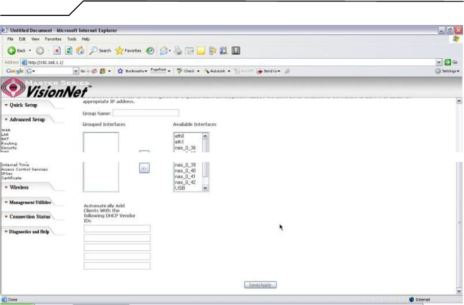
To properly configure a new port mapping, follow the instructions provided on screen.
It is recommended that an experienced telephone company technician configure these
settings for you. In most cases, this will already be configured for you, so no change or
modification is necessary.
Once you have mapped your ports to the desired interfaces, click on the 揝ave/Apply?
button to save these settings.
- 38 -
Manual Ver1.0
Figure 44. Advanced Setup ?Port Mapping ?Add new port map
.
- 39 -