DQ Technology M505 ADSL2+ 4 PORT WIRELESS MODEM W/USB User Manual
DQ Technology, Inc. ADSL2+ 4 PORT WIRELESS MODEM W/USB Users Manual
UserManual.wiki
>
DQ Technology
>
M505 User Manual
>
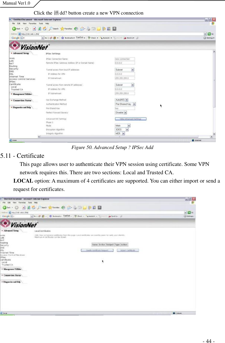
USERS MANUAL 2
Contents
1.
USERS MANUAL 1
2.
USERS MANUAL 2
USERS MANUAL 2
Navigation menu
Upload a User Manual
Namespaces
Wiki Guide
HTML
PDF
Info
Views
User Manual
Discussion / Help
Navigation