DQ Technology M505NR31 ADSL2+ / Ethernet WAN Gateway User Manual
DQ Technology, Inc. ADSL2+ / Ethernet WAN Gateway Users Manual
Users Manual

36
VisionNet M505N
Manual Version: 0.1e
Model: M505N
Product Manual
Product Description: Broadband Gateway
WAN: ADSL2+ / Ethernet WAN
Ethernet: Qty 4 - 10/100 Ethernet
USB: 2.0
WiFi: 802.11 b/g/n 2T2R 2.4Ghz with Internal Airgain Antenna
Manual Date: December 2014
Page 1 of User Manual Rev 0.1e

36
VisionNet M505N
Table of Contents
SECTION 1: MANAGEMENT ACCESS
1.1 MANAGEMENT ACCOUNTS 6
1.2 GUI ACCESS 7
1.3 CLI ACCESS 8
SECTION 2: WAN CONFIGURATION
2.1 WAN LOGIC OVERVIEW 9
2.2 X DSL LOGIC 12
2.3 CUSTOMIZING X DSL PARAMETERS 14
2.4 DEFINING PHYSICAL WAN PORT OPERATION 15
2.5 CREATING AN ATM INTERFACE 16
2.6 CREATING A PTM INTERFACE 18
2.7 CREATING AN ETHERNET INTERFACE 19
2.8 CREATE/MODIFY A BRIDGED WAN SERVICE 20
2.9 CREATE/MODIFY A IPOE WAN SERVICE 22
2.10 CREATE/MODIFY A PPPOE WAN SERVICE 26
SECTION 3: IPv4 LAN CONFIGURATION
3.1 IPv4 CONFIGURATION 30
SECTION 4: WIFI CONFIGURATION
4.1 ENABLE/DISABLE WIFI 31
4.2 CONFIGURE SSID SPECIFIC SETTINGS 32
4.3 WIFI SECURITY 33
4.4 WIFI RADIO SETTINGS 34
SECTION 10: PRODUCT SPECIFICATION
10.1 PRODUCT DEPICTION 35
10.2 LED FUNCTIONALITY 36
10.3 REGULATORY ADVISORIES 37
Page 2 of User Manual Rev 0.1e
363Page of VisionNet M505N
SECTION 1: MANAGEMENT ACCESS
User Manual Rev 0.1e
364VisionNet M505N
SECTION 1.1 MANAGEMENT ACCOUNTS
Item 1 Management Accounts
It has been common practice, in the past, for in-field technicians, and lower level remote support, to receive full
admin access.
As of “Solution Suite 3” , multiple accounts are utilized for department appropriate access to VisionNet modems.
Item 2 Security Advisory
Strict adherence to the following account access restrictions is advised:
High Level Access Limited to Network Design and High Level Support departments
Medium Level Access Limited to in-field installers and ISP employed customer support
Low Level Access ONLY THIS LEVEL ACCESS SHOULD BE PROVIDED TO END
USERS
Page of User Manual Rev 0.1e
365VisionNet M505N
SECTION 1.2 GUI ACCESS
STEP 1 Verify IP Information
1.A Determine the IP and Port of the service
interface.
If you are accessing the unit remotely:
Determine the WAN IP and Service Port.
Verify that your local IP will not be blocked by any
gateway, or network, ACLs.
If you are accessing the unit locally:
Determine the LAN IP of the gateway.
In a NAT, or Routed configuration, this will be your
Gateway IP, assigned by DHCP.
In a Bridged configuration, you will need to statically
assign an IP, to your device, within the same subnet
as the gateway’s unadvertised LAN IP.
Step 2 Connect via Web Browser
2.A In your browser’s address bar, enter the IP
Address and, if remote, port number used for
access.
Example of WAN Access:
http://172.20.100.18
Example of LAN Access:
http://192.168.6.1
2.B When Challenged, enter the username and
password associated with your account.
Page of User Manual Rev 0.1e
366 VisionNet M505N
SECTION 1.3 CLI ACCESS
STEP 1 Verify IP Information
1.A Determine the IP and Port of the service
interface.
If you are accessing the unit remotely:
Determine the WAN IP and Service Port.
Verify that your local IP will not be blocked by any
gateway, or network, ACLs.
If you are accessing the unit locally:
Determine the LAN IP of the gateway.
In a NAT, or Routed configuration, this will be your
Gateway IP, assigned by DHCP.
In a Bridged configuration, you will need to statically
assign an IP, to your device, within the same subnet
as the gateway’s unadvertised LAN IP.
Step 2 Connect via Client
2.A Via your OS Terminal, or Console Program,
you may enter the IP and Port information
Example of WAN Access:
172.20.100.18
Example of LAN Access:
192.168.6.1
2.B When Challenged, enter the username and
password associated with your account.
Page of User Manual Rev 0.1e
367VisionNet M505N
SECTION 2: WAN CONFIGURATION
SECTION 2.1 WAN LOGIC OVERVIEW
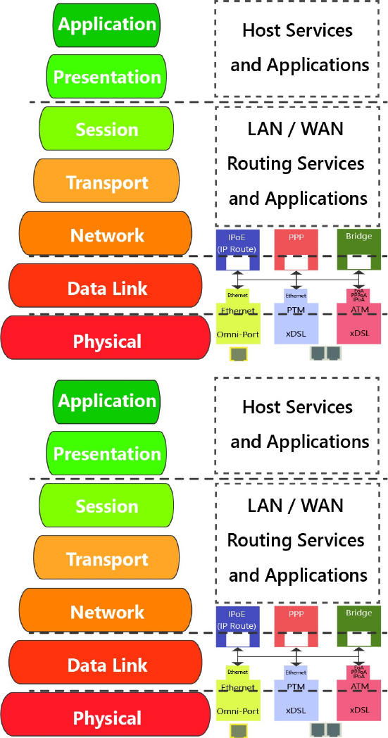
Item 1 OSI RELATION
1.A WAN IF (Interfaces)
There are three possible “Layer 1 – 2” WAN
Configurations Available
ATM
Available for: xDSL Interface
Most Commonly Associated with ADSL
PTM
Available for: xDSL Interface
Most Commonly Associated with VDSL2
ETH
Available for: Omni-Port WAN Interface
Building This Interface Removes the “Omni-
Port” from LAN Operation
Configured Here:
Physical WAN Interfaces Used, Data Link, VLAN
Mux, QoS, ATM PVC’s, ATM Non-Ethernet
Services.
1.B WAN Services
There are three possible “Layer 2 – 3” WAN
Configurations Available
Bridged
Available for: ATM, PTM, ETH
Passes Traffic – No Routing
IPoE
Available for: ATM, PTM, ETH
Routing, WAN Clients (DHCP, RADVD, ETC),
Firewall Type, NAT, Proxies
PPP
Available for: ATM, PTM, ETH
PPP Client, Routing, WAN Clients (DHCP,
RADVD, ETC), Firewall Type, NAT, Proxies
Configured Here:
Service Type, VLAN Tagging, Routing Services, IP
Services, WAN Clients and Proxies
Page of User Manual Rev 0.1e
368VisionNet M505N
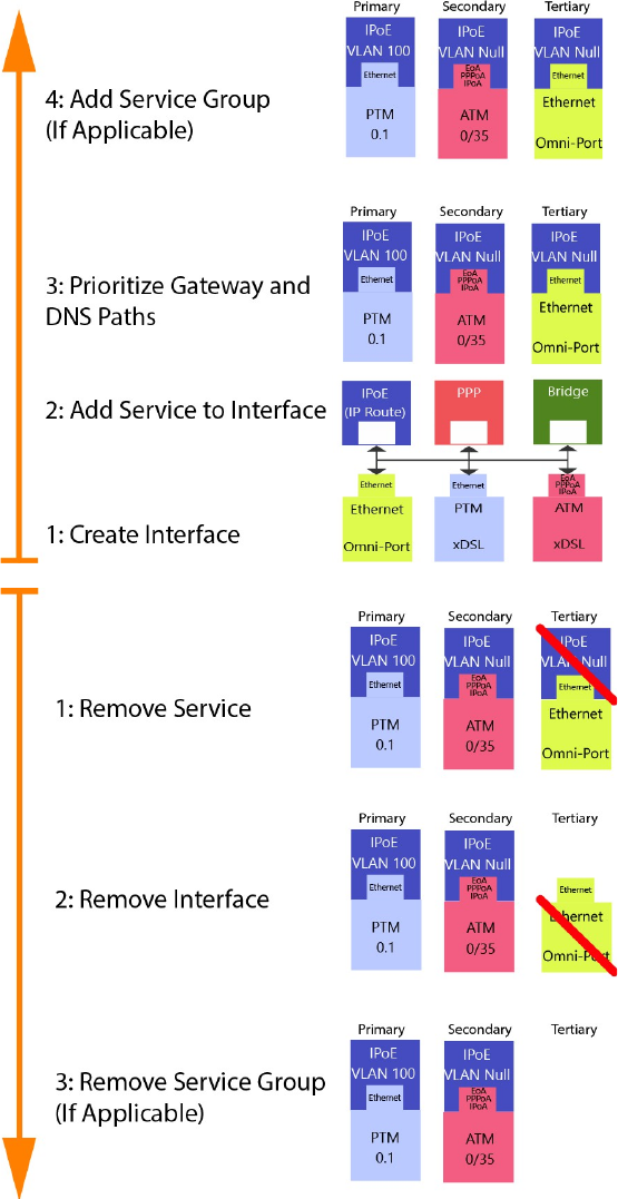
Item 2 WAN Creation / Deletion
2.A Building WAN Services
WAN Services Must be added as follows
1: Add & Define WAN Interface
ATM
PTM
ETH (Omni-Port)
2: Add and Define Service to Interface
ATM
PTM
ETH (Omni-Port)
3: Prioritize for Default Service Group
Gateway
DNS
4: Add Service Group
If Applicable
2.B Tearing Down WAN Services
WAN Services Must be removed as follows:
1: Remove WAN Service
This must be removed first
2: Remove Interface
This may not be removed unless all
associated WAN Services are removed
3: Remove Service Group
Remaining Group Interfaces will not be
ungrouped by default
Page of User Manual Rev 0.1e
9 of 36VisionNet M505N
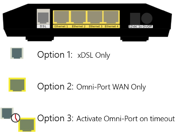
Item 3 Physical Port Prioritization
3.1 There are three Physical WAN Options
xDSL Operation
This operation only allows the xDSL port
to be used for WAN operation.
This will not convert the “Omni-Port” to
LAN mode if an “ETH” Interface is enabled
Omni-Port WAN Operation
This operation only allows WAN Service
through the Omni-Port.
This will not remove created xDSL
Services
WAN Time-out Operation
If xDSL signal is not detected, within a
specified amount of time (default 120
seconds), the created Omni-Port WAN
Interface will be activated.
Page User Manual Rev 0.1e
3610VisionNet M505N
SECTION 2.2 x DSL LOGIC
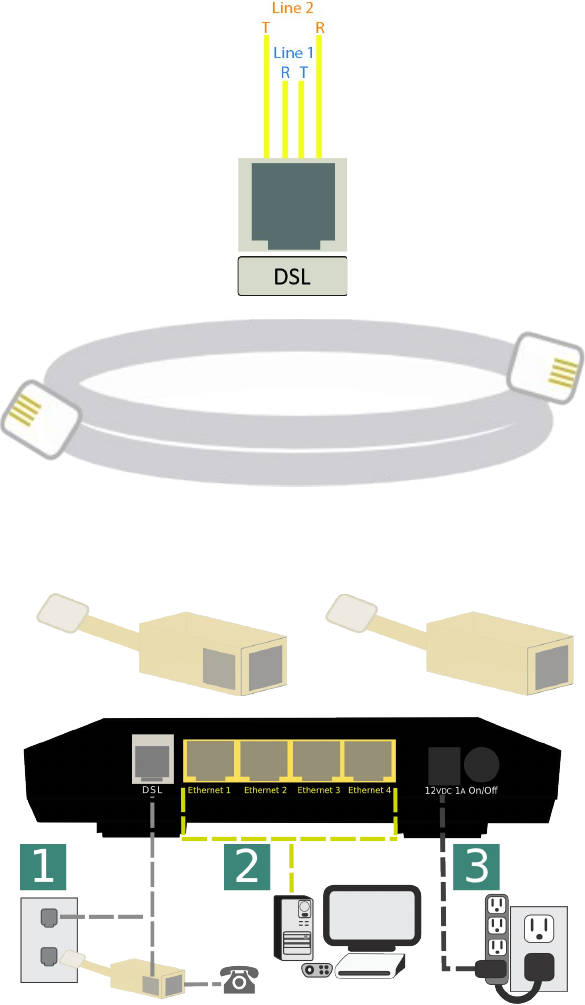
Item 1 x DSL Physical Interfaces
1.A xDSL Port Layout
Line Pinout
The CPE is designed to operate on one
line 1 Only. Only pins for Line 1 are
provided
1.B xDSL Line Cord Preferences
VisionNet provides a standard xDSL cable
Item 2 Physical Installation
2.A Filters may be provided by VisionNet, or
provided by a 3rd party to your company
Dual Line Filter Single Line Filter
2.B 1) Connect DSL
DSL May be connected directly to wall jack
A dual port filter may be used as well.
2) Connect Ethernet Devices
Ethernet is suggested for gaming consoles,
servers, and other synchronous, latency
dependent, applications
3) Connect Power
Connect power to Surge Protector
The over-voltage protection in the provided
PSU is not designed to replace a proper surge
protector.
Page of User Manual Rev 0.1e

3611VisionNet M505N
2.B ADSL2+
ADSL – ADSL2+
Operating Frequency:
20 Khz – 2.2 Mhz
MaxSpeed:
24Mbps DS, 2.2Mbps US
General Operation:
ATM (PTM on some CO equipment)
Item 3 xDSL Properties
Below, is a brief summary of some xDSL protocols to familiarize yourself with:
Page of User Manual Rev 0.1e
Standard ITU Standard
ADSL G.992.1 1.1
ADSL2 G.992.3 1.1
ADSL2+ G.992.5 2.2
Max
Frequency
(Mhz)
Class Protocol Standard Notes
ADSL G.DMT ITU G.992.1 8Mbps DS / 1.3 Mbps US
ADSL G.Lite ITU G.992.2 1.5 Mbps DS / 512 kbps US
ADSL T1.413 ANSI T1.413 8Mbps DS / 1.3 Mbps US
ADSL2 ADSL2 ITU G.992.3 12 Mbps DS / 800 kbps US
ADSL2 Annex L ITU G.992.3 Increases ADSL2 Reach to 7 km (23k ft)
ADSL2+ ADSL2+ ITU G.992.5 Doubles Frequency Range from 1.1Mhz to 2.2 Mhz.
ADSL2+ Annex M ITU G.992.5 Changes DS / US frequency split, to double US to max 3.3 Mbps
Capability Bitswap ITU G.992.1 Allows for movement of bit transmission between "bins"
Capability SRA ITU G.992.5 ADSL2+: Allows for rate changes without re-training
Capability Trellis Multiple Modulation Scheme Rate / Reach performance improvement
PhyR Proprietary ADSL2+: Physical Layer ReTransmission - Broadcom support only
Capability Interleave ITU G709 Forwarding Error Correction / delay preferred <5ms
Capability
3612VisionNet M505N
SECTION 2.3 CUSTOMIZING xDSL PARAMETERS
Abstract
This section will provide instructions on changing xDSL parameters. Upon changing parameters, your modem will need to re-
train; and you will be temporarily disconnected from WAN side connections.
This section will not explain, in detail, the various ATM based options; these should be specified by an ISPs Network Operations
Center and OSP Manager.
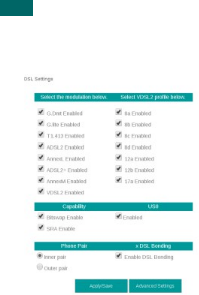
Step 1 Direct your browser to the xDSL Properties page
1.A In the left-hand navigation pane, select: WAN
xDSL Properties
Step 2 Select the appropriate parameters for xDSL configuration
2.A Select Parameters
The necessary parameters will be dictated by
your network, DSLAM capabilities, and profile
considerations
xDSL Properties
2.B Select “Save / Apply”
Page of User Manual Rev 0.1e
3613VisionNet M505N
SECTION 2.4 DEFINING PHYSICAL WAN PORT OPERATION
Abstract
This section will provide instruction in specifying the physical Port used for WAN Service
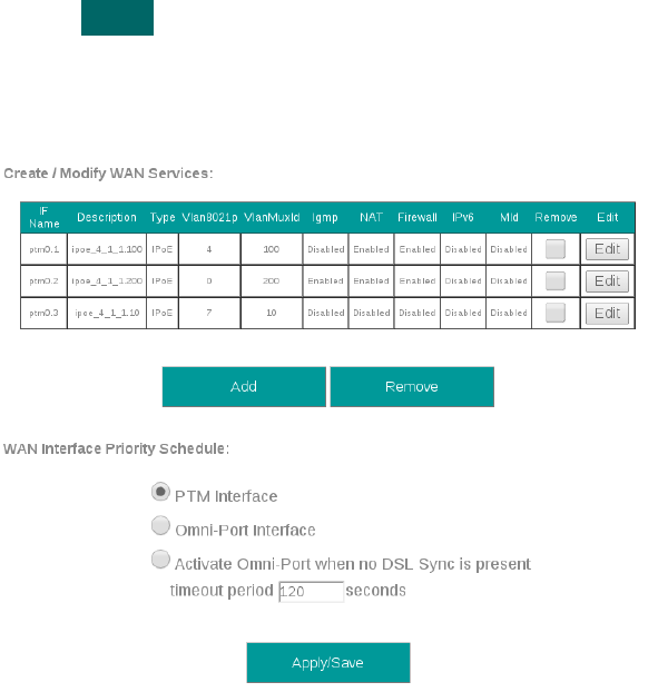
Step 1 Direct your browser to the WAN IF: Services page
1.A In the left-hand navigation pane, select: WAN
WAN IF: Services
Step 2 Select the appropriate parameters for WAN Interface Selection
2.A xDSL Interface:
In some FW Revisions, this is labeled PTM.
ATM is also supported in this mode.
Omni-Port Interface
An Ethernet interface and service must be
created
Time-out
Enable Omni-Port, when no DSL Sync is
present, within specified time after boot-up.
2.B Select “Save / Apply”
Page of User Manual Rev 0.1e
3614VisionNet M505N
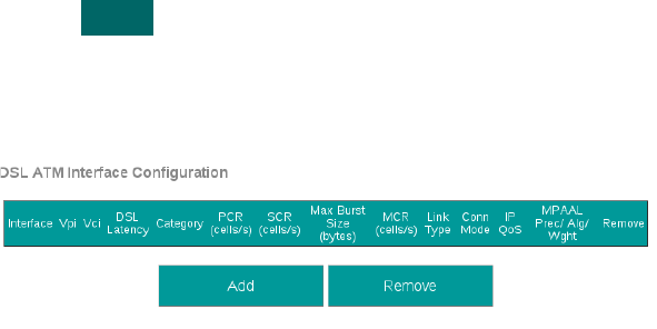
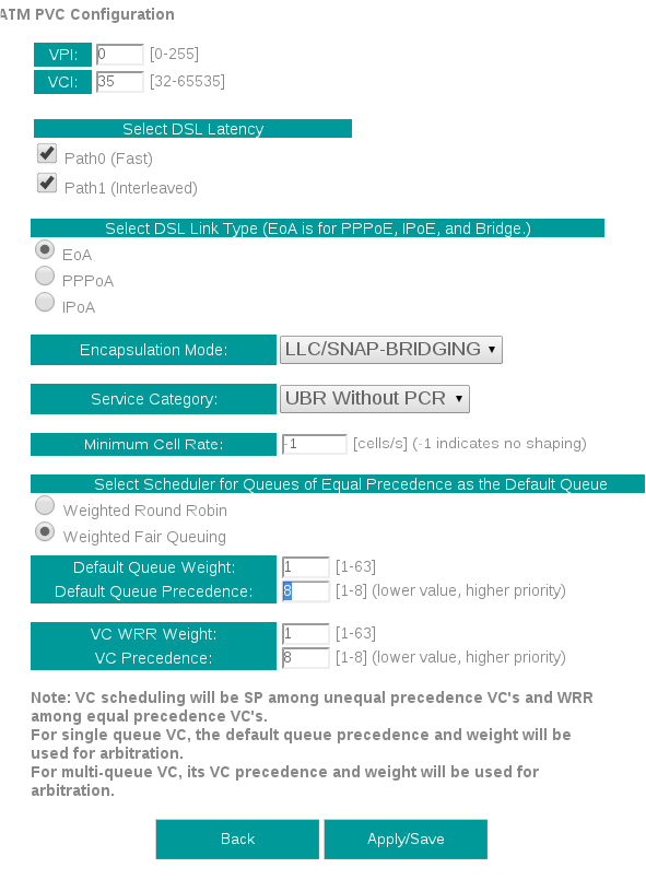
SECTION 2.5 CREATING AN ATM INTERFACE
Abstract
This section will demonstrate the creation of an ATM Interface, most commonly used for ADSL/2/2+ Operation.
This section will not explain, in detail, the various ATM based options; as this must be specified by an ISPs Network Operations
Center and OSP Manager.
Step 1 Direct your browser to the WAN IF: ATM page
1.A In the left-hand navigation pane, select: WAN
WAN IF: ATM
Step 2 Create an ATM Interface
2.A Select “Add”
Notes:
You must remove, and rebuild, an interface if
you would like to change parameters.
Associated WAN Services must be removed,
before an interface may be removed.
Page of User Manual Rev 0.1e
3615VisionNet M505N
2.B Modify Parameters
Notes:
VPI/VCI
If you are using more than one vlan, create
one PVC. The VLANs will be added during
WAN Service configuration.
DSL Latency
If “Interleave” (PATH 1) is to be selected,
“Fast” (PATH 0) must also be selected
DSL Link Type
EoA (Ethernet over ATM)will be used for all
Ethernet based Bridge, PPP, and IP Services;
PPPoA and IPoA are exclusively ATM based
Encapsulation Mode
Default: LLC/Snap-Bridging
Service Category
Default: UBR without PCR
Minimum Cell Rate:
Default : -1
QoS Scheduler
Select WRR or WFQ
You may select Queue Weight and
Precedence for the ATM.
This will affect QoS Prioritization for upstream
traffic only.
2.C Select “Apply / Save”
Page of User Manual Rev 0.1e
3616VisionNet M505N
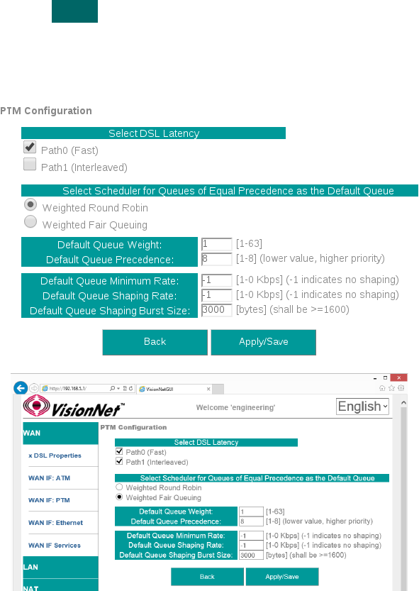
SECTION 2.6 CREATING A PTM INTERFACE
Abstract
This section will demonstrate the creation of a PTM Interface, most commonly used for VDSL2 Operation.
This section will not explain, in detail, the various PTM based options; as this must be specified by an ISPs Network Operations
Center and OSP Manager.
Step 1 Direct your browser to the WAN IF: PTM page
1.A In the left-hand navigation pane, select: WAN
WAN IF: PTM
Step 2 Create a PTM Interface
2.A Select “Add”
Notes:
You must remove, and rebuild, an interface if
you would like to change parameters.
Associated WAN Services must be removed,
before an interface may be removed.
2.B Modify Parameters
Notes:
VLAN MUX
VLAN MUX is enabled by default.
DSL Latency
If “Interleave” (PATH 1) is to be selected, “Fast” (PATH 0)
must also be selected
QoS Scheduler
Select WRR or WFQ
You may select Queue Weight and Precedence for the
ATM.
This will affect QoS Prioritization for upstream traffic only.
2.C Select “Apply / Save”
Page of User Manual Rev 0.1e

3617VisionNet M505N
SECTION 2.7 CREATING AN ETHERNET INTERFACE
Abstract
This section will demonstrate the creation of an Ethernet nterface, most commonly used for VDSL2 Operation.
This section will not explain, in detail, the various Ethernet based options; as this must be specified by an ISPs Network
Operations Center and OSP Manager.
Step 1 Direct your browser to the WAN IF: Ethernet page
1.A In the left-hand navigation pane, select: WAN
WAN IF: ETHERNET
Step 2 Create an Ethernet Interface
2.A Select “Add”
Notes:
You must remove, and rebuild, an interface if
you would like to change parameters.
Associated WAN Services must be removed,
before an interface may be removed.
2.B Select Ethernet Port
Notes:
It is strongly suggested that the “Omni-Port”
be used for WAN Operation.
The option to use another port if available, in
the event that another
2.C Select “Apply / Save”
Page of User Manual Rev 0.1e
3618VisionNet M505N
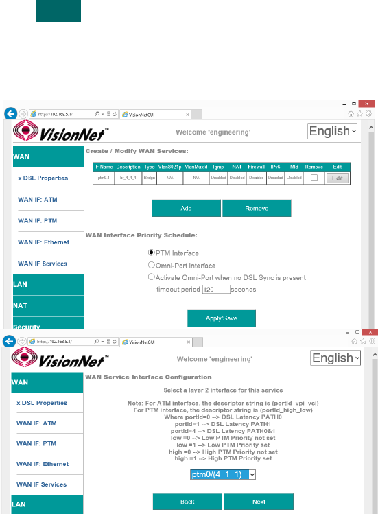
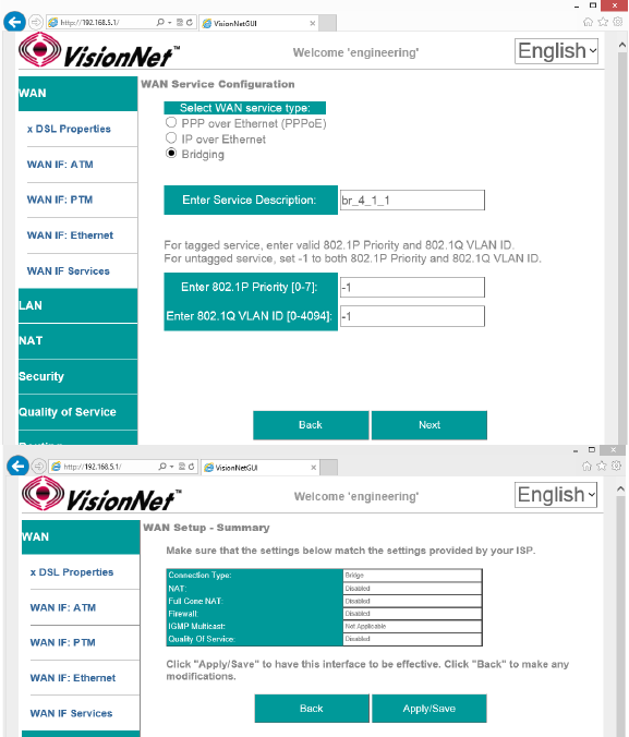
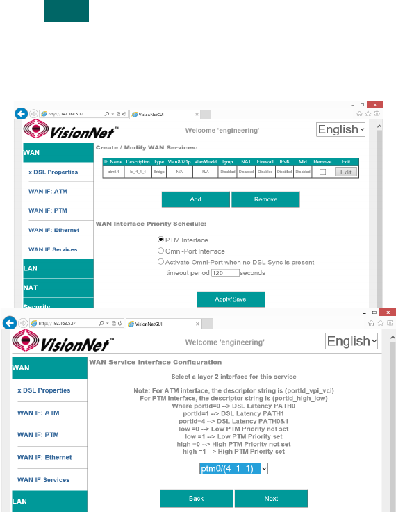
SECTION 2.8 CREATE / MODIFY A BRIDGED WAN SERVICE
Abstract
This section will explain creating a Bridged WAN Service; which removes any routing services from the WAN interface.
This section will not explain, in detail, the various options; as this must be specified by an ISP's Network Operations Center and
OSP Manager.
Step 1 Direct your browser to the WAN IF: Services page
1.A In the left-hand navigation pane, select: WAN
WAN IF: Services
Step 2 Create a WAN Interface
2.A Select “Add”
Notes:
NOTE: If you wish to modify an existing
connection; select the “EDIT” button located
in the table row of the desired interface
2.B Select Desired Interface
This is the Interface that will be used for
the Bridged Service
Upon selection, select “Next”
Page of User Manual Rev 0.1e
36 of 19VisionNet M505N
2.C Specify Basic WAN Services
WAN Service Type: Bridging
Service Description: User Defined
802.1p: If untagged, leave as -1 (Null)
802.1q: If untagged, leave as -1 (Null)
Once complete, select “Next”
2.D WAN Summary
Upon Review, select “Apply/Save”
Page User Manual Rev 0.1e

3620VisionNet M505N
SECTION 2.9 CREATE / MODIFY AN IPOE WAN SERVICE
Abstract
This section will explain creating an IPoE WAN Service; which enables routing services.
This section will not explain, in detail, the various options; as this must be specified by an ISPs Network Operations Center and
OSP Manager.
Step 1 Direct your browser to the WAN IF: Services page
1.A In the left-hand navigation pane, select: WAN
WAN IF: Services
Step 2 Create a WAN Interface
2.A Select “Add”
Notes:
NOTE: If you wish to modify an existing
connection; select the “EDIT” button located
in the table row of the desired interface
2.B Select Desired Interface
This is the Interface that will be used for
the Bridged Service
Upon selection, select “Next”
Page of User Manual Rev 0.1e
3621VisionNet M505N
2.C Specify Basic WAN Services
WAN Service Type: IPoE
Service Description: User Defined
802.1p: If untagged, leave as -1 (Null)
802.1q: If untagged, leave as -1 (Null)
Network Protocol: IPv4, Dual Stack, or IPv6
Once complete, select “Next”
2.D Specify WAN IP Settings
WAN Service Type: IPoE
IPv4
Enable DHCP client plus desired additional
DHCP Options
or enter Static IP Parameters
IPv6:
Specify applicable IPv6 Addresses
Static IPv6 may be applied; but is not
advisable.
Once complete, select “Next”
2.E Specify WAN Services
NAT:
Translation from WAN to LAN IPs
Full Cone NAT:
Augments NAT by keeping translated port
associations open
Firewall:
Necessary for Management Services, Port
Forwarding, etc.
Enable IGMP Multicast:
Only to be used, for IPTV WAN Services,
where IGMP proxy is required. Do not enable
otherwise.
No Multicast VLAN Filter
Page of User Manual Rev 0.1e
3622VisionNet M505N
Monitor all VLANs
Enable MLD Multi-Cast Proxy
Allows MLD outside of local domain
Once complete, select “Next”
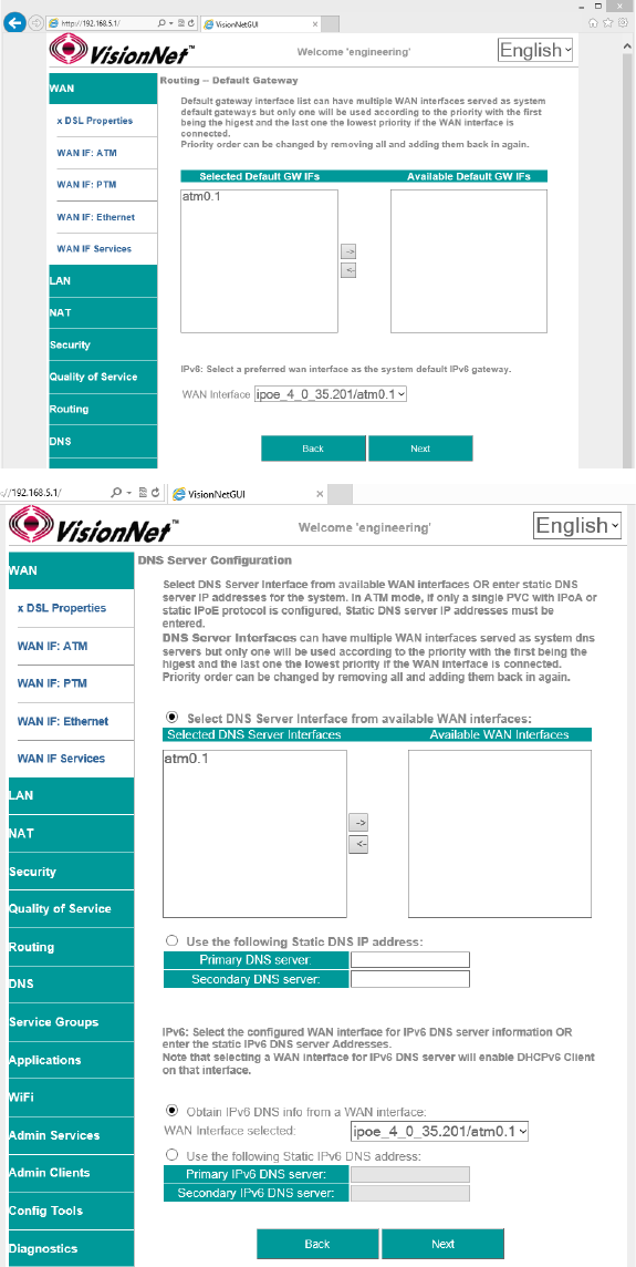
2.F Add Service to Gateway Priority List
(Not available in WAN Modification; For post
creation Modification See Section 4.1)
The Service will be available in the “Available
Default GWs column”.
Upon selection, you may place with the
“Selected Default Gateways” column.
Gateway prioritization runs from top to
bottom, and may be re-prioritized by
removing WAN services from the left column;
and then re-entering them in the desired
order.
You may also select the IPv6 Default
Gateway interface.
2.G Add Service to DNS Priority List
(Not available in WAN Modification; For post
creation Modification See Section X)
The Service will be available in the “Available
WAN Interfaces column”.
Upon selection, you may place with the
“Selected DNS Server Interfaces” column.
DNS Service Prioritization runs from top to
bottom, and may be re-prioritized by
removing WAN services from the left column;
and then re-entering them in the desired
order.
You may also select the IPv6 Default DNS
Interface.
Page of User Manual Rev 0.1e
3623VisionNet M505N
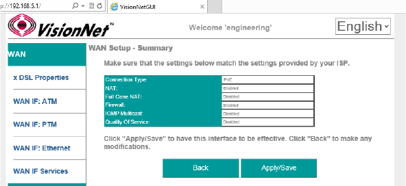
2.H WAN Summary
Upon Review, select “Apply/Save”
Page of User Manual Rev 0.1e
3624VisionNet M505N
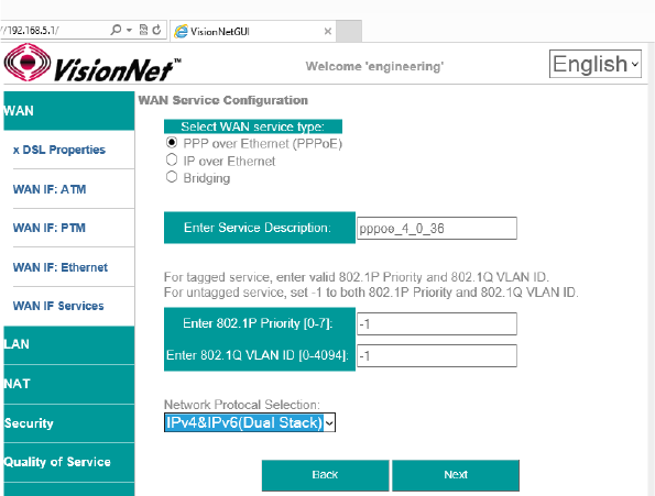
SECTION 2.10 CREATE / MODIFY A PPP WAN SERVICE
Abstract
This section will explain creating a PPP WAN Service, which may be used for routed, or proxied, IP services.
This section will not explain, in detail, the various options; as this must be specified by an ISPs Network Operations Center and
OSP Manager.
Step 1 Direct your browser to the WAN IF: Services page
1.A In the left-hand navigation pane, select: WAN
WAN IF: Services
Step 2 Create a WAN Interface
2.A Select “Add”
NOTE: If you wish to modify an existing
connection; select the “EDIT” button located
in the table row of the desired interface
2.B Select Desired Interface
This is the Interface that will be used for
the Bridged Service
Upon selection, select “Next”
Page of User Manual Rev 0.1e
3625VisionNet M505N
2.C Specify Basic WAN Services
WAN Service Type: PPPoE
(PPPoA is only available if selected during
ATM Creation; if this is the case, then there
will be no option to select services)
Service Description: User Defined
802.1p: If untagged, leave as -1 (Null)
802.1q: If untagged, leave as -1 (Null)
Network Protocol: IPv4, Dual Stack, or IPv6
Once complete, select “Next”
Page of User Manual Rev 0.1e
3626VisionNet M505N
2.D Specify WAN IP Settings
PPP Authentication Client
Username
Password
Service Name (usually blank)
Authentication Method (usually AUTO)
NAT:
Translation from WAN to LAN IPs
Full Cone NAT:
Augments NAT by keeping translated port
associations open
Firewall:
Necessary for Management Services, Port
Forwarding, etc.
Dial on Demand:
If enabled, PPP will disconnect, after the
specified period of time, until hosts request
internet access
PPP IP Extension
Disables NAT, and forward IP to first DHCP
requesting host from LAN.
Static IP Settings
If Static IPs for v4, or v6, are to be assigned in
lieu of DHCP
IPv6 Settings
IPv6 DHCP / RADVD settings
PPP Debug Mode
Sends all PPP service activity to syslog – for
testing only
Bridge PPPoE Frames between WAN and
Local Ports
Allows PPP Requests to be made from LAN
Hosts
Enable IGMP Multicast:
Only to be used, for IPTV WAN Services,
where IGMP proxy is required. Do not enable
otherwise.
Enable MLD Multi-Cast Proxy
Allows MLD outside of local domain
Once complete, select “Next”
Page of User Manual Rev 0.1e
3627VisionNet M505N
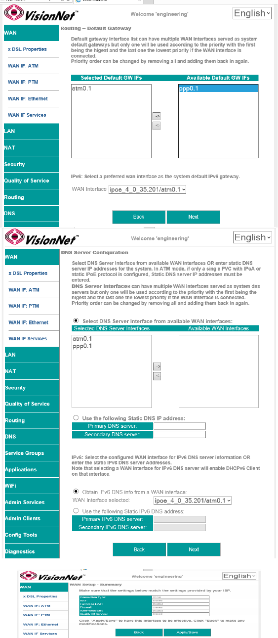
2.E Add Service to Gateway Priority List
(Not available in WAN Modification; For post
creation Modification See Section 4.1)
The Service will be available in the “Available
Default GWs column”.
Upon selection, you may place with the
“Selected Default Gateways” column.
Gateway prioritization runs from top to bottom,
and may be re-prioritized by removing WAN
services from the left column; and then re-
entering them in the desired order.
You may also select the IPv6 Default Gateway
interface.
2.F Add Service to DNS Priority List
(Not available in WAN Modification; For post
creation Modification See Section X)
The Service will be available in the “Available
WAN Interfaces column”.
Upon selection, you may place with the
“Selected DNS Server Interfaces” column.
DNS Service Prioritization runs from top to
bottom, and may be re-prioritized by removing
WAN services from the left column; and then
re-entering them in the desired order.
You may also select the IPv6 Default DNS
Interface.
2.G WAN Summary
Upon Review, select “Apply/Save”
Page of User Manual Rev 0.1e
3628VisionNet M505N
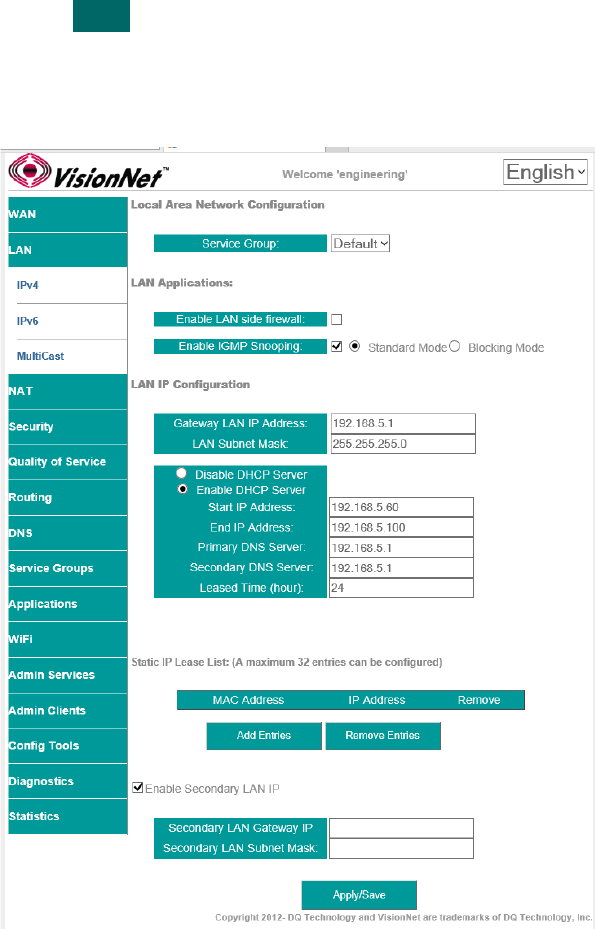
SECTION 3: IPv4 LAN CONFIGURATION
SECTION 3.1 IPv4 Configuration
Abstract
This section will depict the configuration of LAN broadcast groups. Each service group has separate IP, broadcast, and multi-
cast domains. You must configure LAN Services for each service group
Step 1 Direct your browser to the LAN IPv4 page
1.A In the left-hand navigation pane, select: LAN
IPv4
Step 2 Configure Service Group LAN Parameters
2.A Service Group
Select Service Group to Modify
LAN Firewall
When enabled, hosts will not be able to
manage device via Service Group LAN
IP.
Enable IGMP Snooping
When enabled, the IGMP Multicast
controller will be enabled.
Standard Mode will enable snooping
Blocking Mode will prevent Multicasts
LAN IP Configuration
Gateway IP / Subnet
This will serve as the LAN Gateway IP for
hosts.
DHCP Server
Configure DHCP Range within Gateway
Subnet
Enter Gateway IP, for DNS Servers, if
proxy is to be used.
Enter custom DNS Servers if desired.
DNS Proxy may be by-passed (WAN
DNS will be passed to devices). See
Section 4.X
DHCP Reservation (Static IP Lease)
Reserve IPs, within the Primary Gateway
Subnet, based upon hosts MAC
Addresses
Enable Secondary LAN IP
A secondary LAN IP may be
implemented. No DHCP Services are
assigned to this interface
Step 3 When finished, select “ Apply / Save “.
Page of User Manual Rev 0.1e
3629VisionNet M505N
SECTION 4: WiFi Configuration
SECTION 4.1 Enable / Disable WiFi
Abstract:
WiFi may be enabled / disabled
Step 1 Direct your browser to the SSID page
1.A In the left-hand navigation pane, select: WiFi
SSID
Step 2 Enable / Disable WiFi
2.A Check / Uncheck the box labeled “Enable
Wireless”
Step 3 When finished, select “ Apply / Save “.
It may take up to 1 minute for your change to take effect
Page of User Manual Rev 0.1e

3630VisionNet M505N
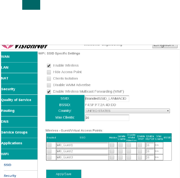
SECTION 4.2 Configure SSID Specific Settings
Abstract:
SSID Specific settings may be altered for optimized interoperability
Step 1 Direct your browser to the SSID page
1.A In the left-hand navigation pane, select: WiFi
SSID
Step 2 SSID Related Settings
2.A ENABLE WIRELESS
This enables / Disables WiFi
services
HIDE ACCESS POINT
If this is selected, the SSID name will
not be broadcasted
CLIENTS ISOLATION
This prevents ad-hoc networks; but
could impede upon some
applications (ie: printing)
Disable WMM Advertise
WMM is required for modern
MultiMedia applications. Disable
only for support of legacy devices.
This will lower aggregate speed
Enable WMF
Wireless Multicast Forwarding is
useful for modern Media Sharing
applications
SSID Name
This is the broadcasted SSID name
Virtual / Guest networks
Mutliple SSIDs may be broadcasted
(ie: temporary access). Clients will
operate on the primary LAN
Step 3 When finished, select “ Apply / Save “.
It may take up to 1 minute for your change to take effect
Page of User Manual Rev 0.1e
3631VisionNet M505N
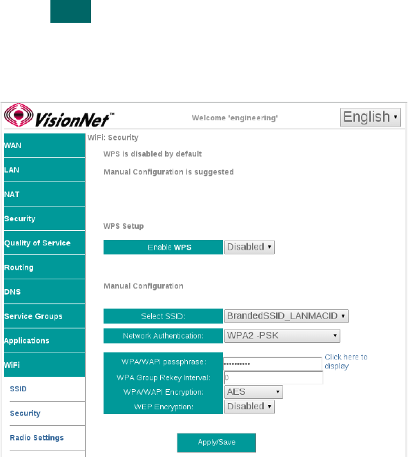
SECTION 4.3 WiFi Security
Abstract:
WiFi Security should always be enabled. The following directions will provide detail on configuration.
Step 1 Direct your browser to the SSID page
1.A In the left-hand navigation pane, select: WiFi
Security
Step 2 SSID Related Security Settings
2.A Enable WPS
Suggested Configuration - Disabled
SSID
Select SSID
Network Authentication
Suggested Setting: WPA2-PSK
WPA Passphrase
This may be any passphrase that you
like.
WPA Group Rekey Interval
Suggested Setting: 0
WPA Encryption
Suggested Setting: AES
WEP Encryption
Suggested Setting: Disabled
Step 3 When finished, select “ Apply / Save “.
It may take up to 1 minute for your change to take effect. You will need to
“forget” old network settings and re-connect all devices after making this
change.
Page of User Manual Rev 0.1e
3632VisionNet M505N
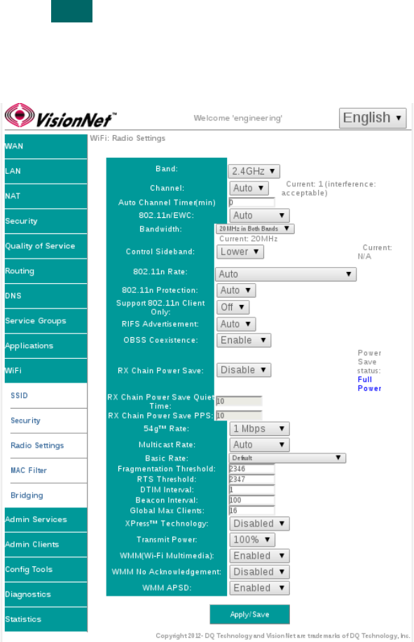
SECTION 4.4 WiFi Radio Settings
Abstract:
Most radio settings should be left as default. Below, are key settings for optimizing performance.
Step 1 Direct your browser to the SSID page
1.A In the left-hand navigation pane, select: WiFi
Radio Settings
Step 2 SSID Related Security Settings
2.A Band:
This device only supports 2.4Ghz
Channel:
Auto will allow the device to auto-select a channel. This will
also allow the WiFi button, located on the top front of the
device, to change the channel.
802.11n/EWC
Suggested Setting: Auto
802.11n Auto
Suggested Setting: Auto
802.11n Protection
Suggested Setting: Off
802.11n Client Only
Suggested Setting: Off
RIFS Advertisment
Suggested Setting: Auto
OBSS Coexistence
Suggested Setting: Enabled
RX Chain Power Save
Suggested Setting: Disabled
RX Chain Power Save Quiet Time:
Suggested Setting: 10
RX Chain Power Save PPS:
Suggested Setting: 10
54g Rate
Suggested Setting:1Mbps
Multicast Rate
Suggested Setting: Disabled
Basic Rate
Suggested Setting: Default
Fragmentation Threshold
Suggested Setting: 2346
RTS Threshold
Suggested Setting: 2347
DTIM Threshold
Suggested Setting: 1
Beacon Interface
Suggested Setting: 100
Global Max Clients:
Suggested Setting: 16
Xpress Technology
Suggested Setting: Disabled
Transmit Power
Suggested Setting: 100%
WMM
Suggested Setting: Enabled
WMM No Acknowledgement
Suggested Setting: Disabled
WMM APSD
Suggested Setting: Enabled
Step 3 When finished, select “ Apply / Save “.
It may take up to 1 minute for your change to take effect.
Page of User Manual Rev 0.1e
3633VisionNet M505N
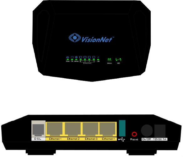
SECTION 5: Product Specifications
SECTION 5.1 Product Depictions
Front Depiction
Back Depiction
Page of User Manual Rev 0.1e

3634VisionNet M505N
SECTION 5.2 LED Functionality
Label Description Functionality
Power Status Power / Router Solid Green – Power On
Off – Power Off
Flashing Green 2 hz – Flashing Power on self test
Flashing Red 4 hz- Failure (not bootable) or device malfunction
A malfunction is any error of internal sequence or state that will prevent the device
From connecting to the DSLAM or passing customer data. This may be identified at
various times such after power on or during operation through the use of self testing or in
operations which result in a unit state that is not expected or should not occur.
Ethernet 1 Status Ethernet Port Off - Power Off – or – No Powered device detected
Solid Green – Powered device connected ; including wake on LAN
Flashing Green – LAN activity present for that port
Ethernet 2 Status Ethernet Port Off - Power Off – or – No Powered device detected
Solid Green – Powered device connected ; including wake on LAN
Flashing Green – LAN activity present for that port
Ethernet 3 Status Ethernet Port Off - Power Off – or – No Powered device detected
Solid Green – Powered device connected ; including wake on LAN
Flashing Green – LAN activity present for that port
Ethernet 4 Status Ethernet Port Off - Power Off – or – No Powered device detected
Solid Green – Powered device connected ; including wake on LAN
Flashing Green – LAN activity present for that port
LED Location specifies Link Status 10 / 100 / GbE
Wireless Status WiFi Off - Modem off or Wireless not activated
Solid Green – Wireless activated
Flashing Green 2 hz– WPS Activated – Association Period
Flashing Green 4 Hz - Wireless Activity
Note: Pressing the WiFi button enables a re-scan of the WiFi Spectrum
WPS Status WPS Off: WPS Not in use
Solid Green: Devices authenticated via WPS
Flashing Green: WPS authenticated activated, authenticating devices
Note: Presseing the WPS button enables WPS if enabled in the GUI
DSL Status DSL Link Line 1 Green – DSL Good Sync
Off - Powered off
Flashing Green - DSL Attempting sync
Signal Detection – Flashing 2hz with 50% duty cycle
Carrier Detected, Modem training – Flashing at 4hz with 50% duty cycle
Internet Status Internet Connection Internet Light – Must indicate at least one type of connection
Solid Green – IP connected – no traffic passing
Device has a WAN IP via either static/ DHCP/ or IPCP
If PPP is used, device has authenticated and has a WAN IP Address
If IP or PPPOE session is idle and dropped, light to remain green as long as ADSL is still
present. Light to turn red if upon attempting new session it fails.
Off – Modem Power Off.
LED Should remain off if modem is in bridged mode or if DSL Connection is not present
Flashing Green – Device has WAN IP Address and IP Traffic is passing through device
Red – Device attempted initiate session, either authentication or to obtain an IP Address, and
failed. an IP Address, and failed.
Page of User Manual Rev 0.1e
3635VisionNet M505N
SECTION 5.3 Regulatory Advisories
FCC Caution:
Any changes or modifications not expressly approved by the party responsible for compliance could void the
user's authority to operate the equipment.
VisionNet
Model: M505N
FCC ID: QMPM505NR31 US: DQ1DL01BM505NR31
This device complies with part 15 of the FCC Rules.
Operation is subject to the following two conditions:
(1) This device may not cause harmful interference and
(2) this device must accept any interference received, including
interference that may cause undesired operation.
This device complies with FCC part 68 Rules.
IMPORTANT NOTE:
FCC Radiation Exposure Statement:
This equipment complies with FCC radiation exposure limits set forth for an uncontrolled environment. This
equipment should be installed and operated with minimum distance 20 centimeters between the radiator and
your body.
This transmitter must not be co-located or operated in conjunction with any other antenna or transmitter.
This equipment has been tested and found to comply with the limits for a class B digital device, pursuant to
part 15 of the FCC rules. These limits are designed to provide reasonable protection against harmful
interference in a residential installation. This equipment generates, uses, and can radiate radio frequency
energy and, if not installed and used in accordance with the instructions, may case harmful interference to
radio communications. However, there is no guarantee that interference will not occur in a particular
installation.
If this equipment does cause harmful interference to radio or television reception, which can be determined
by turning the equipment off and on, the user is encouraged to try to correct the interference by one or more
of the following measures:
-Reorient or relocate the receiving antenna.
-Increase the separation between the equipment and receiver.
-Connect the equipment into an outlet on a circuit different from that to which the receiver is
connected.
-Consult the dealer or an experienced radio/TV technician for help.
Page of User Manual Rev 0.1e
36 36VisionNet M505N
Customer Information
This equipment complies with Part 68 of the FCC rules. Located on the equipment is a label that contains, among other
information, the ACTA registration number and ringer equivalence number (REN.) If requested, this information must be provided
to the telephone company. The REN is used to determine the quantity of devices which may be connected to the telephone line.
Excessive REN’s on the telephone line may result in the devices not ringing in response to an incoming call. In most, but not all
areas, the sum of the REN’s should not exceed five (5.0). To be certain of the number of devices that may be connected to the
line, as determined by the total REN’s contact the telephone company to determine the maximum REN for the calling area. This
equipment cannot be used on the telephone company-provided coin service. Connection to Party Line Service is subject to State
Tariffs. If this equipment causes harm to the telephone network, the telephone company will notify you in advance that temporary
discontinuance of service may be required. If advance notice isn’t practical, the telephone company will notify the customer as
soon as possible. Also, you will be advised of your right the file a complaint with the FCC if you believe it is necessary.
The telephone company may make changes in its facilities, equipment, operations, or procedures that could affect the operation of
the equipment. If this happens, the telephone company will provide advance notice in order for you to make the necessary
modifications in order to maintain uninterrupted service. If trouble is experienced with this equipment, please contact (Agent in the
US):
Company Name: DQ Technology, Inc. Address: 5111 Johnson Drive, Pleasanton, CA, 94588, USA Tel: +1 925 730 3940 Fax: +1
925 730 3950
If the trouble is causing harm to the telephone network, the telephone company may request you to remove the equipment from
the network until the problem is resolved.
This equipment uses the following USOC jacks: RJ11C It is recommended that the customer install an AC surge
arrester in the AC outlet to which this device is connected. This is to avoid damaging the equipment caused by local lightning
strikes and other electrical surges.
Page of User Manual Rev 0.1e