DQ Technology M605N 5port wifi-N VDSL2/ADSL2+ Gateway W/USB User Manual
DQ Technology, Inc. 5port wifi-N VDSL2/ADSL2+ Gateway W/USB
User Manual

VisionNet M605N Page 1 End User Manual Revision 3.1
Model Number: M605N
Product Description: VDSL2 / ADSL2+ / Ethernet WAN Residential Gateway featuring:
Qty 4 10/100 Ethernet Ports
Qty 1 Gigabit Ethernet Port
Qty 1 USB 2.0
802.11b/g/n 2T2R
End User Manual

VisionNet M605N Page 2 End User Manual Revision 3.1
TABLE OF CONTENTS
SECTION 1: GUI ACCESS
1.1
Accessing the GUI
3
SECTION 2: TROUBLESHOOTING
SECTION 2: TROUBLESHOOTING
2.1
View DHCP Statistics
5
2.2
View ARP Statistics
6
SECTION 3: DNS CONFIGURATION
SECTION 3: WAN CONFIGURATION
3.1
Universal Static WAN DNS Addresses
7
SECTION 4: LAN CONFIGURATION
SECTION 4: LAN CONFIGURATION
4.1
Configuring LAN Services
8
4.2
Reserving an IP Address within the DHCP Server
10
4.3
Configuring UPnP
12
SECTION 5: NAT CONFIGURATION
SECTION 5: NAT CONFIGURATION
5.1
Configuring Port Forwarding
13
5.2
Configuring Port Triggering
17
5.3
Configuring the DMZ Host
21
SECTION 6: WIRELESS CONFIGURATION
SECTION 6: MODEM CONFIGURATION SETTINGS
6.1
Wireless Channel
23
6.2
Wireless SSID
23
6.3
Wireless Security
24

VisionNet M605N Page 3 End User Manual Revision 3.1
SECTION 1: GUI ACCESS
Section 1.1
ACCESSING THE GUI
Step 1: Accessing the GUI via a web browser
1.A
Open your Web Browser
Use the modem’s LAN IP Address
to access the GUI locally
This is most likely
http://192.168.1.254
1.B
If you are not sure what the IP
Address is, you may view the
gateway address assigned, via
DHCP, to the NIC Card of your PC or
Device.
Place the IPv4 Gateway address
into the address bar of your
browser.
VisionNet M605N Page 4 End User Manual Revision 3.1
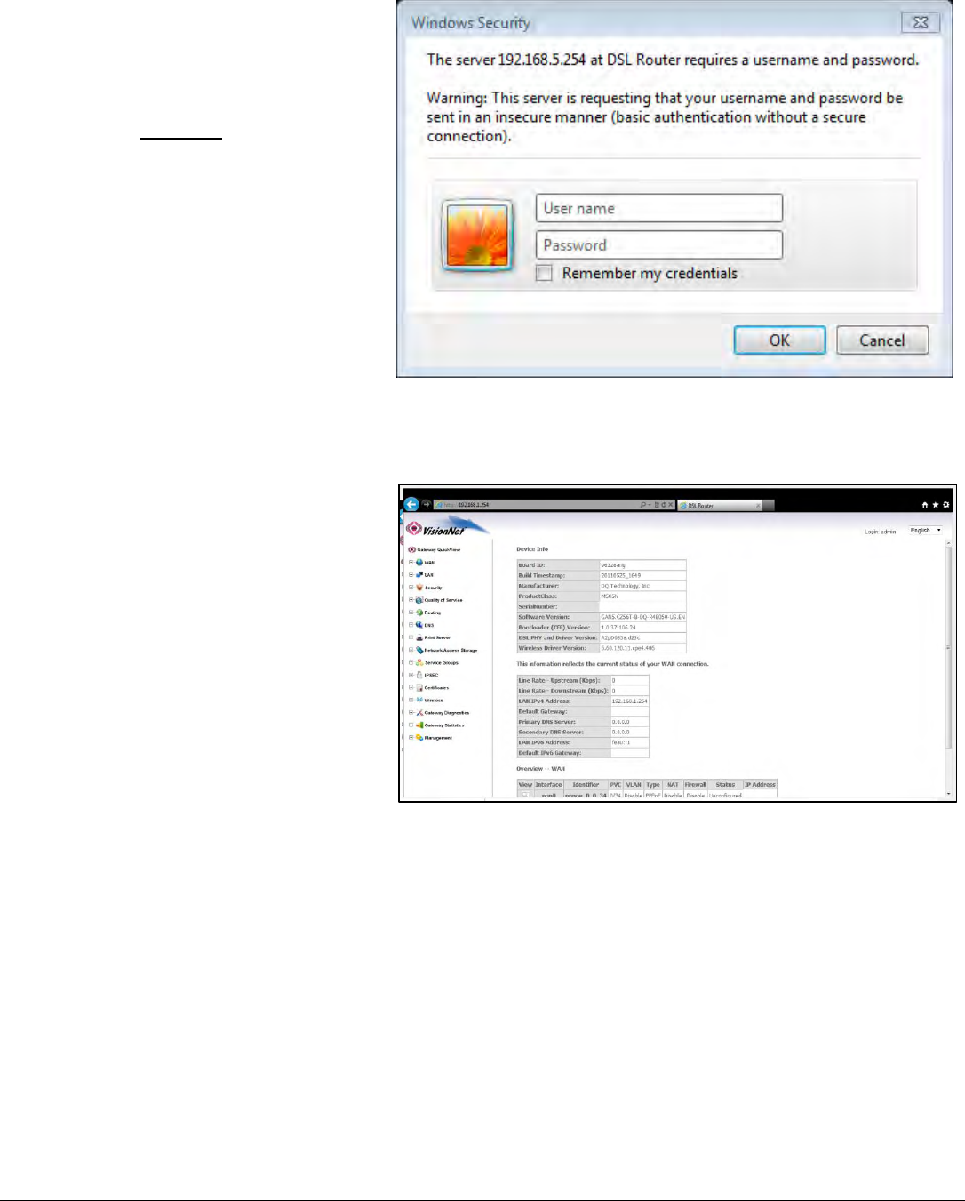
1.C
Once the modem responds, you will be challenged for a User Name and Password
Local Access
Username: enduser
Password: password
1. D
You will be directed to the Main GUI Page
VisionNet M605N Page 5 End User Manual Revision 3.1
SECTION 2: DIAGNOSTICS
Section 2.1
VIEW DHCP STATISTICS
Step 1: Access the GUI to find DHCP Statistics
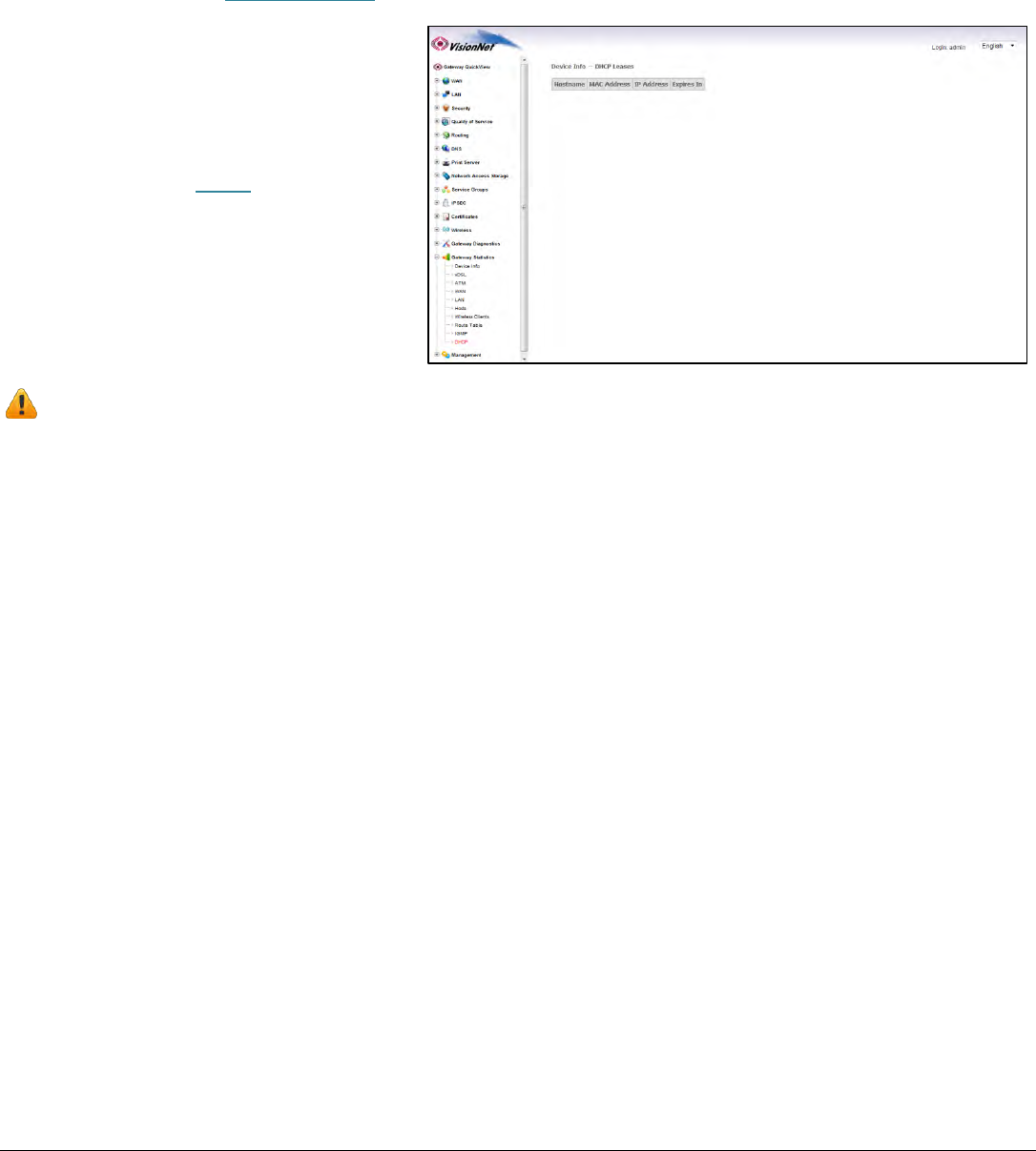
1.A
Select the “Gateway Statistics” tab located within the left-hand frameset.
Then, In the left-hand frameset,
select “DHCP”
WHAT THESE STATISTICS MEAN:
This page will provide the IP Addresses assigned by the modem’s DHCP server, the MAC addresses of dynamically assigned devices,
and the amount of time that the device has spent on the network.
VisionNet M605N Page 6 End User Manual Revision 3.1
Section 2.2
VIEW ARP STATISTICS
Step 1: Access the GUI to find ARP Statistics
This step may be used to view all connected LAN devices, and is especially useful when using the “Reserve an IP Address” feature.
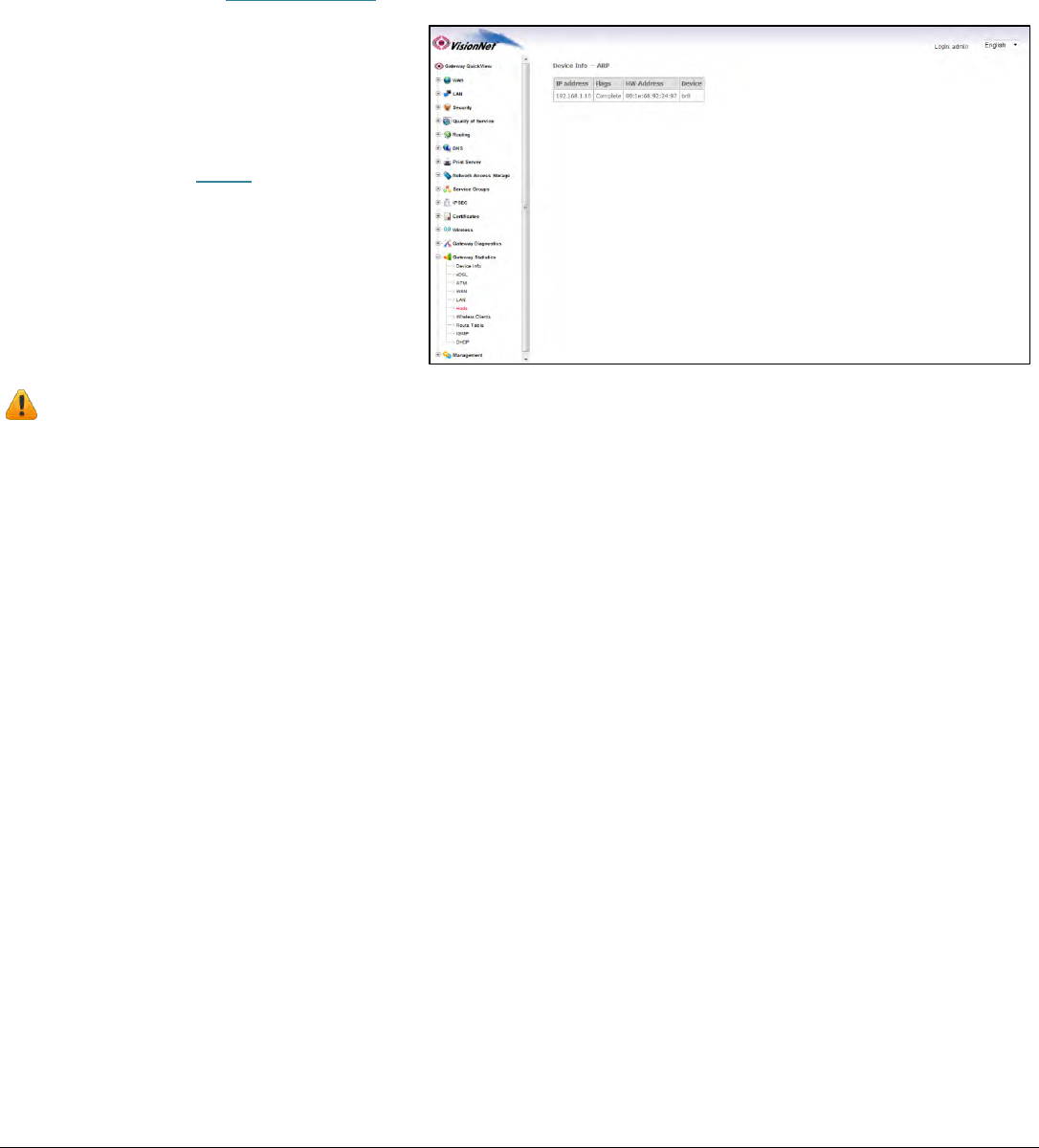
1.A
Select the “Gateway Statistics” tab located within the left-hand frameset.
Then, In the left-hand frameset,
select “Hosts”
WHAT THESE STATISTICS MEAN:
This page will provide the MAC Addresses of all recognized devices connected to the modem. A device will only be recognized once
it has requested data from the modem.
VisionNet M605N Page 7 End User Manual Revision 3.1
SECTION 3: DNS CONFIGURATION
Section 3.1
UNIVERSAL STATIC WAN DNS ADDRESSES
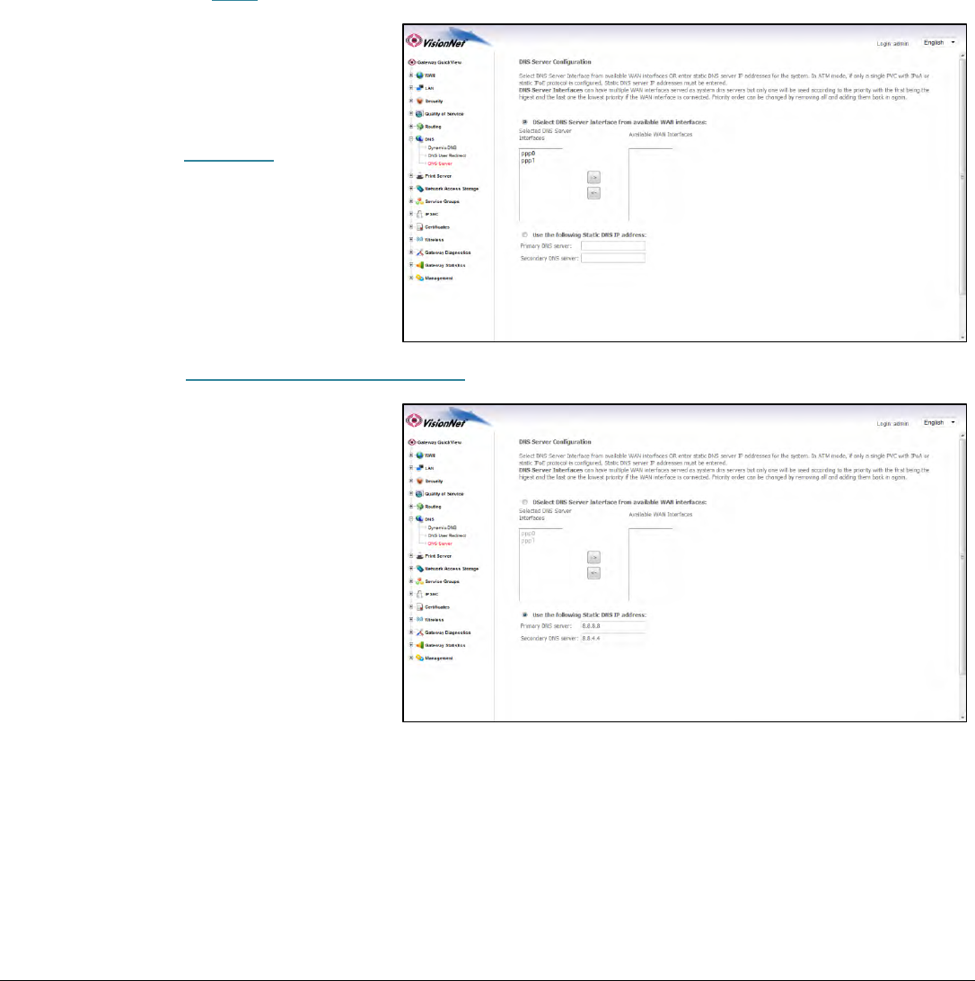
The VisionNet Modem may be assigned different DNS addresses for each WAN Service. In the event that Static IPs are to be used,
you may update and change the settings with the following procedure.
Step 1: Access the GUI to find the DNS Server Page
1.A
Select the “DNS” tab located within the left-hand frameset.
Then, In the left-hand frameset,
select “DNS Server”
1.B
Select “Use the following Static DNS IP Address”
VisionNet M605N Page 8 End User Manual Revision 3.1
SECTION 4: LAN CONFIGURATION
Section 4.1
CONFIGURING LAN SERVICES
Step 1: Direct Your Browser to the LAN Configuration Page
1.A
Select the “LAN” tab located within the left-hand frameset.
Then, In the left-hand frameset,
select “LAN IP CONFIGURATION”
VisionNet M605N Page 9 End User Manual Revision 3.1
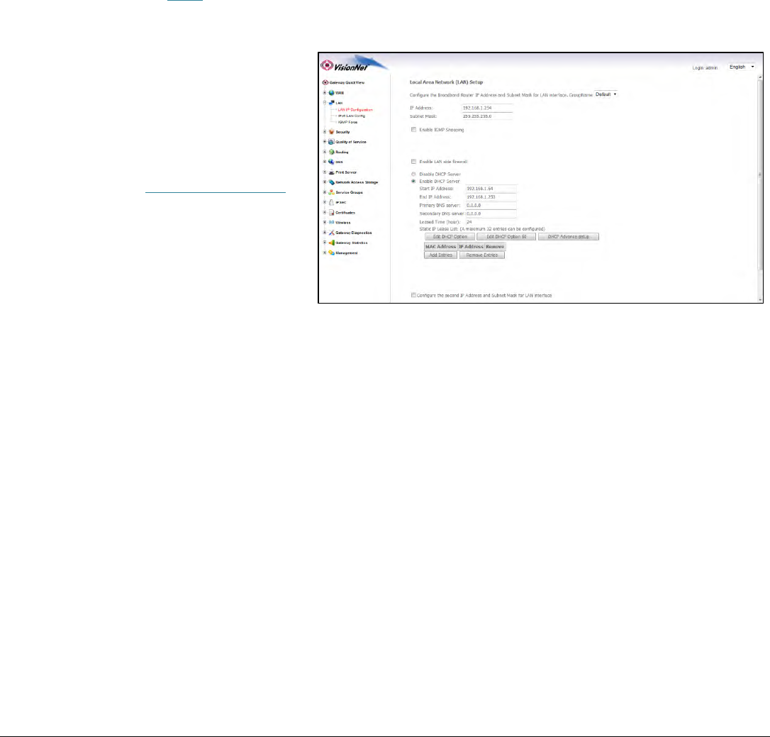
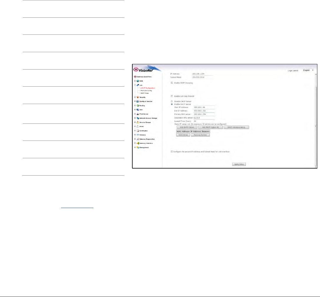
Step 2: Configure LAN Settings
2.A
Configure the LAN IP Characteristics
IP Address:
192.168.1.254
(Unless your
ISP has
specified
another
address)
Subnet Mask:
255.255.255.0
Enable IGMP Snooping:
DO NOT
CHANGE
DHCP Server:
Enabled
Start IP Address:
192.168.1.64
End IP Address:
192.168.1.100
Primary DNS Server:
192.168.1.254
Secondary DNS Server:
192.168.1.254
or another
DNS Server
Leased Time (hour):
24
All other settings
DO NOT
CHANGE
Configure Second IP
Address:
DO NOT
CHANGE
2.B
Select “Apply / Save”
VisionNet M605N Page 10 End User Manual Revision 3.1
Section 4.2
RESERVING AN IP ADDRESS WITHIN THE DHCP SERVER
DEFINITION OF RESERVED IP
Some applications (Such as Port Triggering and DMZ Host) require a Static IP Address. Some devices, however, do not
support Static IP Addresses or are portable in nature.
These devices may be provided a Static IP Address via the DHCP Server. When a Reserved IP Address is specified, the
modem will consistently provide the same dynamic IP Address to the specified MAC Address. The Reserved IP Address will
not be assigned to any other LAN Devices.
Prior to Assigning the Reserved IP Address, you must determine the MAC Address of the target LAN Device. You may
copy the MAC Address from the ARP Table located within the Device Info Section of the GUI.
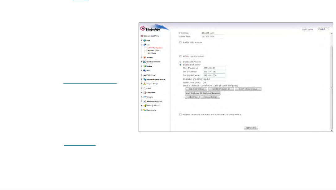
Step 1: Direct Your Browser to the LAN Configuration Page
1.A
Select the “LAN” tab located within the left-hand frameset.
Then, In the left-hand frameset,
select “LAN IP Configuration”
1.B
Select “Add Entries”
VisionNet M605N Page 11 End User Manual Revision 3.1
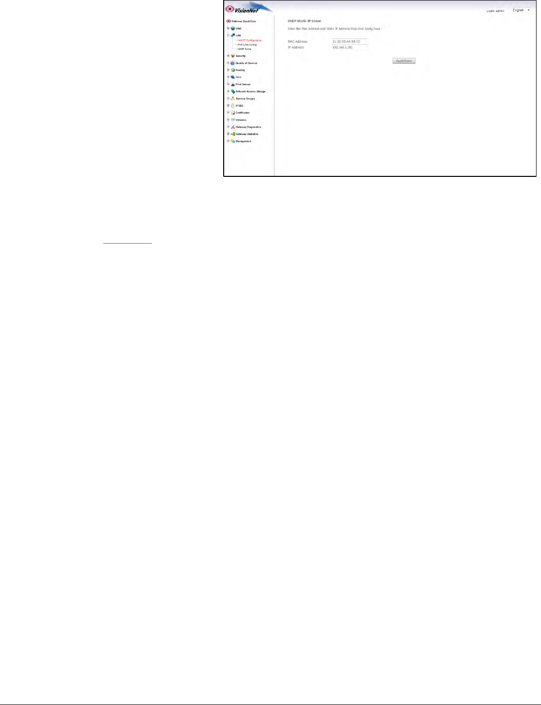
You will be re-directed to the
“DHCP Static IP Lease” Page
Enter the MAC Address of the
intended LAN Host, and the IP
Address that you would like to
permanently allocate to that host.
1.C
Select “Apply Save”
VisionNet M605N Page 12 End User Manual Revision 3.1
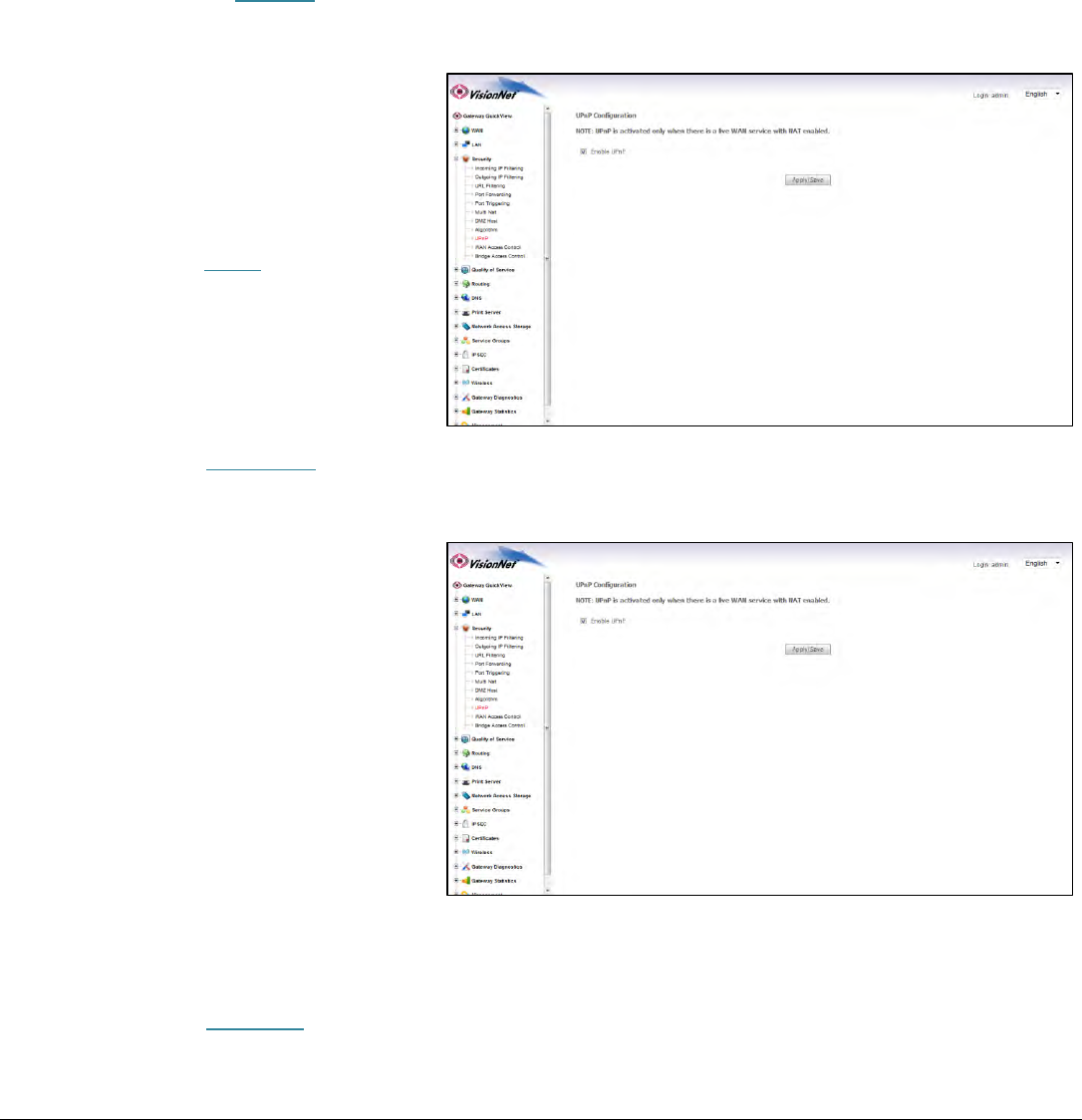
Section 4.3
ENABLING UPnP
UPnP Definition
Some applications, such as the XBOX, will require UPnP for operation. UPnP will dictate how devices share information on
the LAN, and the Dynamic port rules to be used for Internet Content.
Step 1: Direct Your Browser to the UPnP Page
1.A
Select the “Security” tab located within the left-hand frameset.
Then, In the left-hand frameset,
select “UPnP”
1.B
Select “Enable UPnP”
You may enable / disable UPnP by
toggling the checkbox.
1.C
Select “Apply Save”

VisionNet M605N Page 13 End User Manual Revision 3.1
SECTION 5: NAT CONFIGURATION
Section 5.1
CONFIGURING PORT FORWARDING
COMMON APPLICATIONS
XBOX:
UPnP will resolve most XBOX issues, however should you need to do further trouble-shooting the following Port
Forwarding Rules may be enabled
Designation
WAN Port
LAN IP
LAN Port
Protocol
XBOX Live
88
192.168.1.230
88
TCP/UDP
XBOX Live
3074
192.168.1.230
3074
TCP/UDP
The most effective method of utilizing these rules, is to request that the end-user change the IP Address of their XBOX to
the following Static IP settings:
XBOX Configuration
IP Address
192.168.1.230
Subnet Mask
255.255.255.0
Gateway Address
192.168.1.254
DNS Address
192.168.1.254
IP CAMERAS:
The following is an example of IP Camera Configuration
Designation
WAN Port
LAN IP
LAN Port
Protocol
Camera 1
6231
192.168.1.231
80
TCP/UDP
Camera 2
6232
192.168.1.232
80
TCP/UDP
VisionNet M605N Page 14 End User Manual Revision 3.1
The most effective method of utilizing these rules, is to request that the end-user change the IP Address of their Camera to
the following Static IP settings:
IP Camera Configuration
IP Address
192.168.1.23x
Subnet Mask
255.255.255.0
Gateway Address
192.168.1.254
DNS Address
192.168.1.254
The customer will remotely access their camera by pointing their browser to the Public IP Address of the modem, and
appending the appropriate port number. (ie: 67.126.108.104:6231)
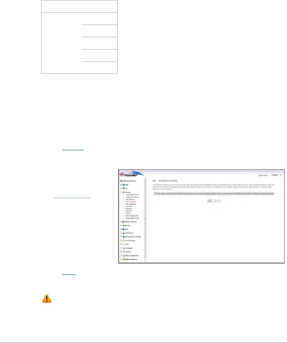
Step 1: Direct Your Browser to the Port Forwarding Configuration Page
1.A
Select the “Security” tab located within the left-hand frameset.
Then, In the left-hand frameset,
select “Port Forwarding”
1.B
Select the “Add” Button.
Please Note: If the port to be assigned is already specified in the existing Port Forwarding Table, you
must remove the rule containing this port prior to creating a new one.
VisionNet M605N Page 15 End User Manual Revision 3.1
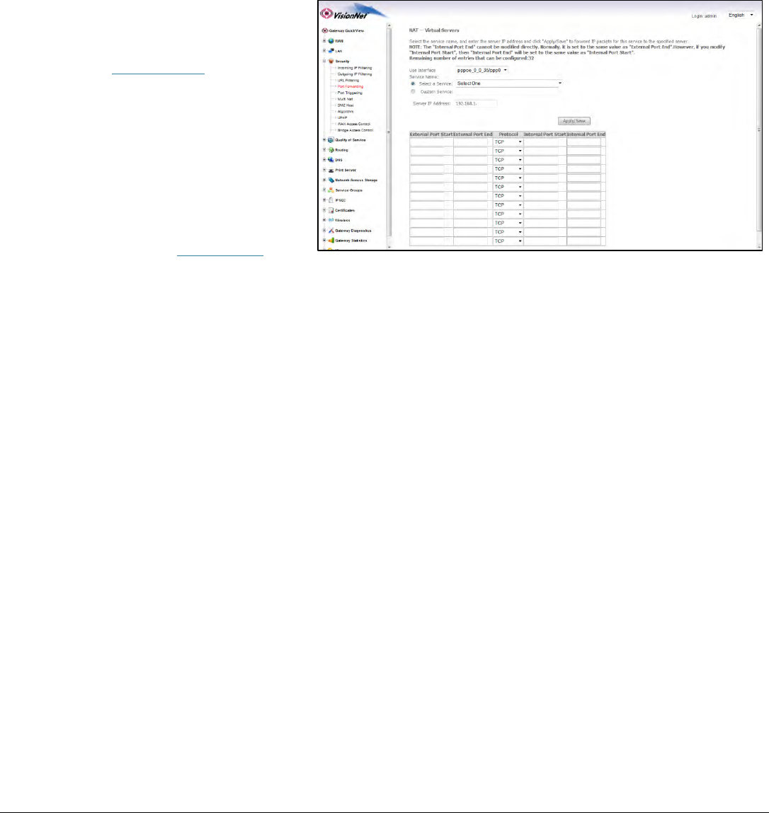
Step 2: Configure the Port Forwarding Rule
2.A
Choose the name of the rule
Choose the appropriate WAN
Interface:
If the Service you would like to
have is already available in the
“Select a Service” menu, you may
select this service for auto-
population.
You may create a custom Service
by selecting “Custom Service” and
entering a new rule name
VisionNet M605N Page 16 End User Manual Revision 3.1
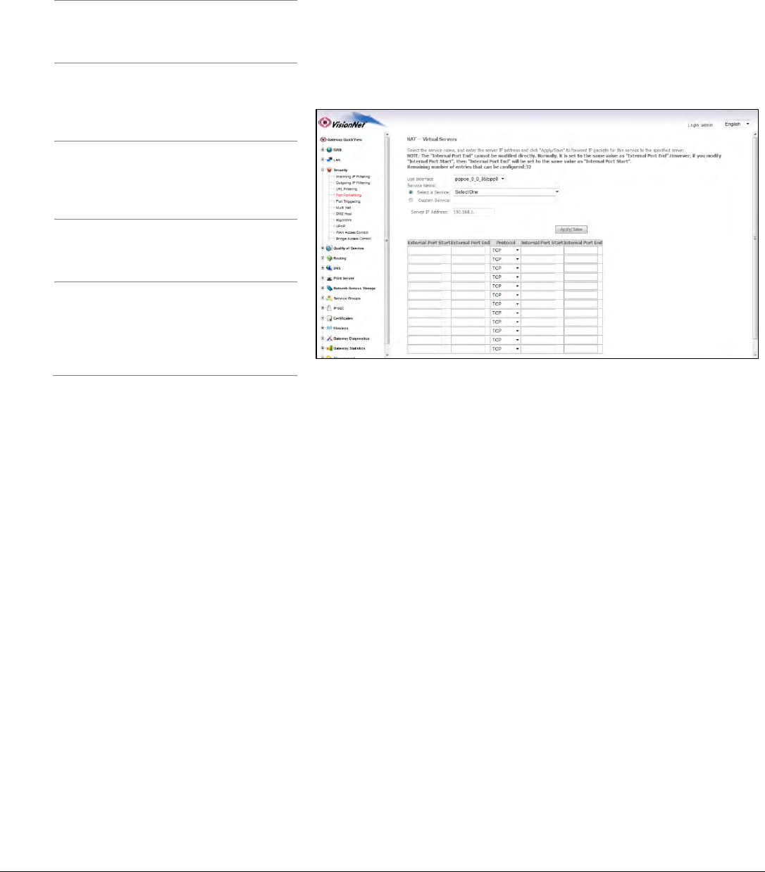
2.B
Enter the port rules
External
Port Start
This is the port that will be
used to access the device on
the WAN Side
External
Port End
This should be the same as
“External Port Start”
Protocol
This should be “TCP/UDP” to
avoid possible errors due to
end-user mis-communication
Internal
Port Start
This should be the port that
the device “listens” on (see IP
Camera example)
External
Port End
This should be the same as
“Internal Port Start”
Remote IP
This should left blank, unless
only one remote device, with
a static IP, will be allowed to
access this port.
2.C
Select “Save/Apply”
2.D
Considerations
For this rule to work properly, the LAN device must have either a Static IP, or a Reserved IP
The LAN Device, and modem, may should be reset to ensure that this rule continues to work correctly

VisionNet M605N Page 17 End User Manual Revision 3.1
Section 5.2
CONFIGURING PORT TRIGGERING
DEFINITION OF PORT TRIGGERING
Port Triggering is a dynamic version of Port Forwarding, in which the modem will dynamically create a temporary port
forwarding rule based upon outbound activity. This is best applied for LAN devices that communicate with a remote
server. Basic VPN functions are already supported by default, but some applications use non-standard communication
methods.
An example would be port triggering configuration for the Nortel Contivity VPN Solution, which uses non-standard port
VPN ports and requires Port Triggering to work.
The following are the port triggering rules required for Nortel Contivity VPNs.
Port Triggering for
Nortel Contivity
VPNs
LAN Device
Outbound Port
Outbound
Protocol
Port Temporarily Forwarded to
Initiating LAN Device
Inbound
Protocol
500
TCP/UDP
500
TCP/UDP
10001
TCP/UDP
10001
TCP/UDP
In this scenario, a LAN Device (ie: The end-user’s laptop) will make an outbound UDP request on ports 500 and 10001. The
modem responds to this by temporarily forwarding ports 500 and 10001 to the IP address of the initiating LAN Device (ie:
The end-users laptop) for the life of the session.
Port Triggering is ideal for portable devices (ie: laptops, PDAs, etc.) which require port forwarding, but for which a Static
LAN IP would be antithetical to the device’s common usage.
VisionNet M605N Page 18 End User Manual Revision 3.1
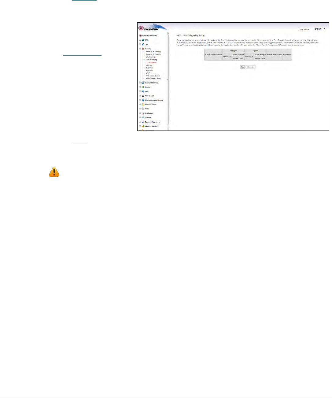
Step 1: Direct Your Browser to the Port Triggering Configuration Page
1.A
Select the “Security” tab located within the left-hand frameset.
Then, In the left-hand frameset,
select “Port Triggering”
1.B
Select the “Add” Button.
Please Note: If the port to be assigned is already specified in the existing Port Triggering Table, you must
remove the rule containing this port prior to creating a new one.
VisionNet M605N Page 19 End User Manual Revision 3.1
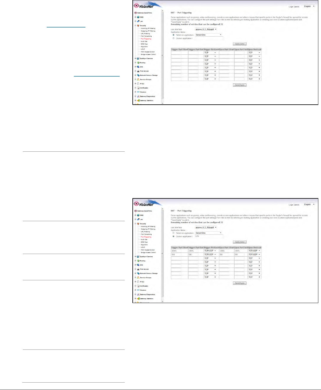
Step 2: Configure the Port Forwarding Rule
2.A
Select the appropriate WAN Interface
If the Service you would like to
have is already available in the
“Select a Service” menu, you may
select this service for auto-
population.
You may create a custom Service
by selecting “Custom Application”
and entering a new rule name
2.B
Enter the port rules
Trigger
Port Start
This is the port that the LAN
device uses to initiate a
session
Trigger
Port End
This will usually match the
“Trigger Port Start” parameter;
some applications, however, may
use a succession of ports.
In this case you will enter the
final port in that range.
If these ports are not in
succession, you must enter the
next port as another row in the
rule
Protocol
This should be “TCP/UDP” to
avoid possible errors due to
end-user mis-communication
Open Port
Start
This is the WAN Port that the
remote server will reply on
Open Port
End
This will usually match the “Open
Port Start” parameter; some
applications, however, may use a
succession of ports.
In this case you will enter the
final port in that range.
If these ports are not in
succession, you must enter the
next port as another row in the
rule
Open Port
Protocol
This should be “TCP/UDP” to
avoid possible errors due to
end-user mis-communication

VisionNet M605N Page 20 End User Manual Revision 3.1
2.C
Select “Save/Apply”
2.D
Considerations
It may be difficult to determine which ports must be used for a particular application. It is best to specify the LAN device
as the DMZ host to see if this resolves the issue.
If this does not resolve the issue, the port triggering rule should be removed and replaced with port forwarding. Once port
forwarding has been verified to work then port triggering may be re-visited. If port triggering does not work, then further
research should be done to identify the behavior of the communication between the LAN device and the Server.
VisionNet M605N Page 21 End User Manual Revision 3.1
Section 5.3
CONFIGURING THE DMZ HOST
DEFINITION OF DMZ Host
In the event that a remote application attempts to communicate via an inactive, or unspecified, port; the port will be
dynamically forwarded to the IP Address specified as the DMZ Host.
If a specific device is to be assigned as a DMZ host, this device should have either a Static IP or a Reserved IP.
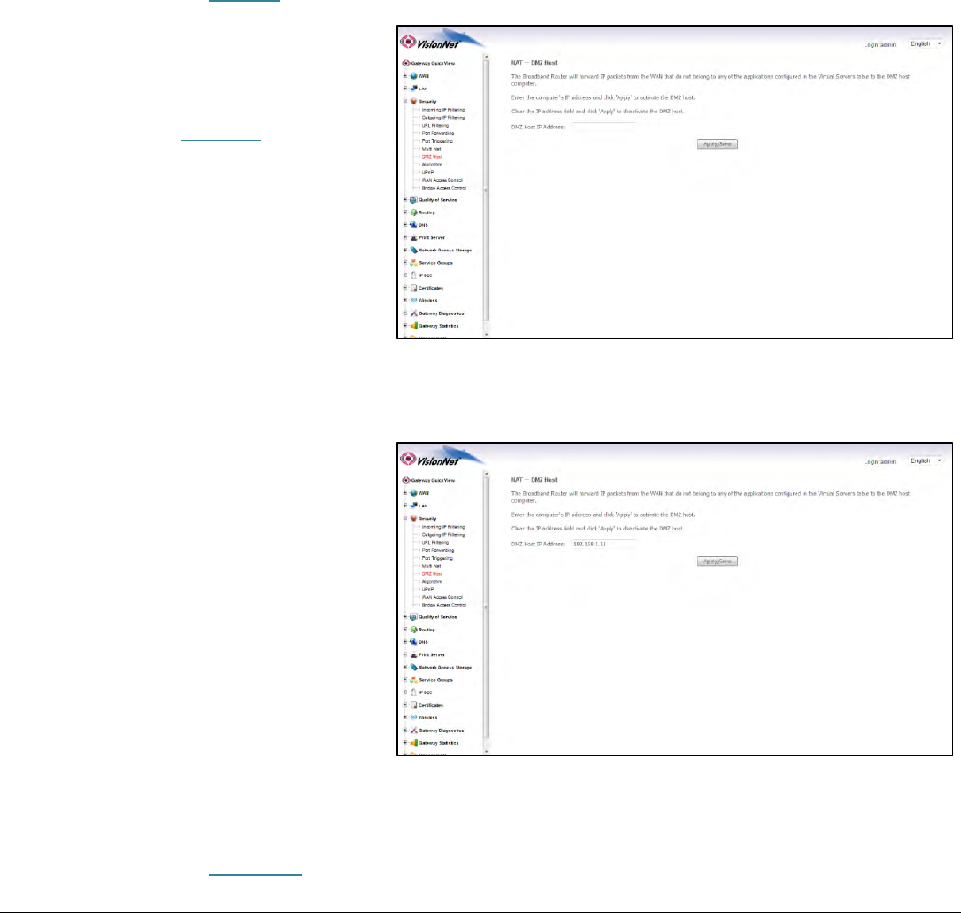
Step 1: Direct Your Browser to the DMZ Host Configuration Page
1.A
Select the “Security” tab located within the left-hand frameset.
Then, In the left-hand frameset,
select “DMZ Host”
1.B
Enter the desired DMZ Host IP Address
This is the IP Address of the LAN Device which
will receive all non-specified traffic.
This device should have either a Static IP or
Reserved IP
1.C
Select the “Save/Apply” Button.
VisionNet M605N Page 22 End User Manual Revision 3.1
SECTION 6: WIRELESS CONFIGURATION
Section 6.1
CHANGING THE WIRELESS CHANNEL
When to change the Wireless Channel.
Many items in your home, and your immediate neighbors’ homes, likely use the 2.4 Ghz range. There are 11 possible channels that
may be used within this spectrum. If your wireless connection becomes very slow, or drops, there may be other devices that are
impeding upon your network. This is when you should consider changing your wireless channel.
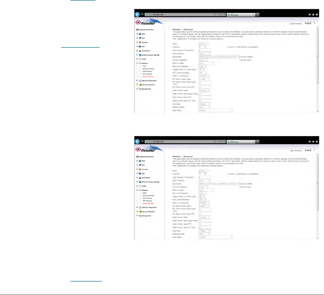
Step 1: Direct Your Browser to the Global Wireless Configuration Page
1.A
Select the “Wireless” tab located within the left-hand frameset.
Then, In the left-hand frameset,
select “Global Settings”
1.B
Enter the desired Channel.
1, 6, and 11 tend to operate the best.
Other Channels to consider are 3 and 9.
Once you have selected the new channel,
select “Save/Apply” at the bottom of the
screen.
1.C
Select the “Save/Apply” Button.
VisionNet M605N Page 23 End User Manual Revision 3.1
Section 6.2
CHANGING THE WIRELESS SSID
When to change the Wireless SSID
You may wish to broadcast a different network name than the one provided.
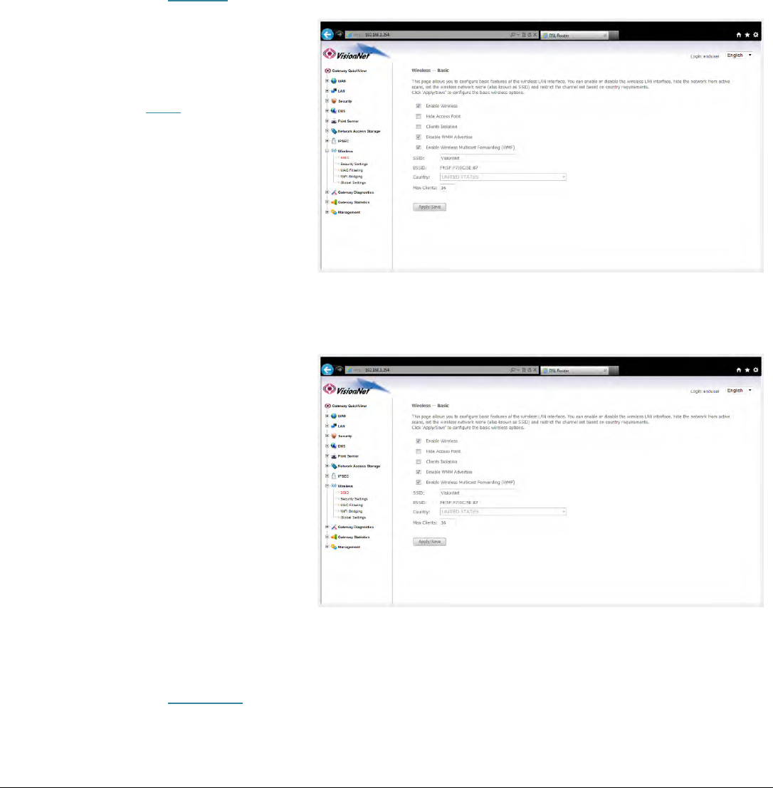
Step 1: Direct Your Browser to the SSID Configuration Page
1.A
Select the “Wireless” tab located within the left-hand frameset.
Then, In the left-hand frameset,
select “SSID”
1.B
Enter the new SSID Name
The following should be enabled:
Enabled Wireless
Disable WMM Advertise
Enable Wireless Multicast Forwarding
Once you have entered the SSID Information,
select “Save/Apply” at the bottom of the
screen.
1.C
Select the “Save/Apply” Button.
VisionNet M605N Page 24 End User Manual Revision 3.1
Section 6.3
CHANGING THE WIRELESS ENCRYPTION
When to change the Wireless Encryption
You may wish to use a special login password for your wireless network.
NEVER LEAVE YOUR NETWORK UNENCRYPTED!!! THIS IS VERY INSECURE AND COULD RESULT IN LEGAL TROUBLE SHOULD AN
UNAUTHORIZED USER USES YOUR NETWORK FOR ILLEGAL ACTIVITY!
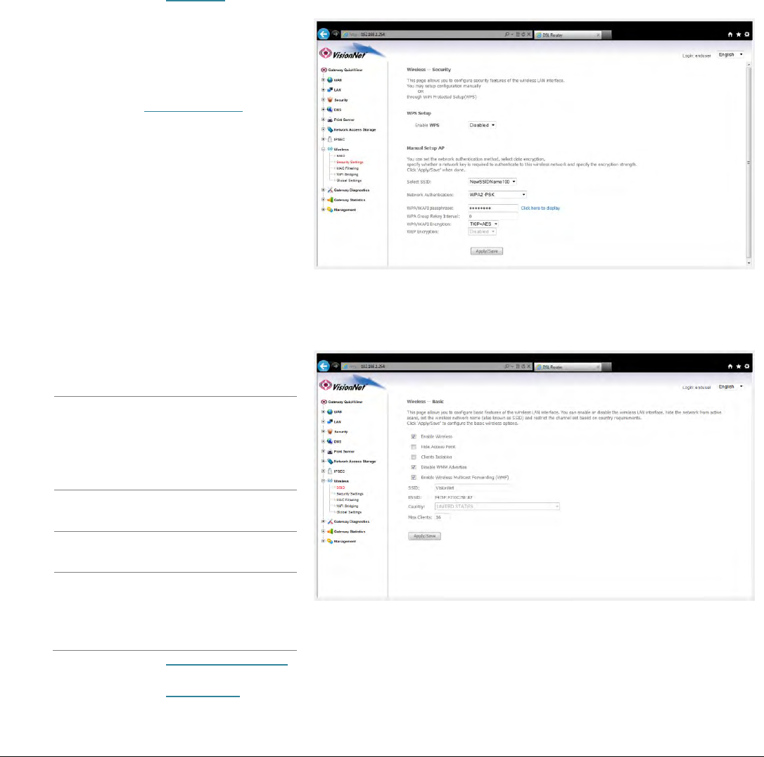
Step 1: Direct Your Browser to the Security Settings Page
1.A
Select the “Wireless” tab located within the left-hand frameset.
Then, In the left-hand frameset,
select “Security Settings”
1.B
Under “Manual Setup AP”
Select SSID
Choose your network
name
Network
Authentication
WPA2-PSK is preferable.
Some devices may
require WPA-PSK
WPA
Passphrase
Enter the new password
Group Rekey
interval
0
WPA
Encryption
AES is preferable
Some devices may
require TKIP+AES
1.C
Select the “Click Here to Display” Button; and verify your encryption key.
1.D
Select the “Save/Apply” Button.
FCC Information
This equipment complies with CFR 47, Part 15.19 of the FCC rules. Operation of
the equipment is subject to the following conditions: (1) this device may not cause
harmful interference, and (2) this device must accept any interference received;
including interference that may cause undesired operation.
This device must not be co-located or operating in conjunction
with any other antenna or transmitter
NOTE: THE MANUFACTURER IS NOT RESPONSIBLE FOR ANY RADIO
OR TV INTERFERENCE CAUSED BY UNAUTHORIZED MODIFICATIONS
TO THIS EQUIPMENT. SUCH MODIFICATIONS COULD VOID THE USER’S
AUTHORITY TO OPERATE THE EQUIPMENT.
Federal Communications Commission (FCC) Requirements, Part 15
This equipment has been tested and found to comply with the limits for a class B
digital device, pursuant to part 15 of the FCC Rules. These limits are designed to
provide reasonable protection against harmful interference in a residential
installation.
This equipment generates, uses and can radiate radio frequency energy and, if not
installed and used in accordance with the instructions, may cause harmful
interference to radio communications. However, there is no guarantee that
interference will not occur in a particular installation. If this equipment does cause
harmful interference to radio or television reception, which can be determined by
turning the equipment off and on, the user is encouraged to try to correct the
interference by one or more of the following measures:
---Reorient or relocate the receiving antenna.
---Increase the separation between the equipment and receiver.
---Connect the equipment into an outlet on a circuit different from that to which
the receiver is connected.
---Consult the dealer or an experienced radio/TV technician for help.
Regulatory information / Disclaimers
Installation and use of this Wireless LAN device must be in strict accordance with
the instructions included in the user documentation provided with the product. Any
changes or modifications (including the antennas) made to this device that are not
expressly approved by the manufacturer may void the user’s authority to operate
the equipment. The manufacturer is not responsible for any radio or television
interference caused by unauthorized modification of this device, or the substitution
of the connecting cables and equipment other than manufacturer specified. It is the
responsibility of the user to correct any interference caused by such unauthorized
modification, substitution or attachment. Manufacturer and its authorized resellers
or distributors will assume no liability for any damage or violation of government
CAUTION: To maintain compliance with FCC’s RF exposure guidelines, this
equipment should be installed and operated with minimum distance 20cm
between the radiator and your body. Use on the supplied antenna.
Unauthorized antenna, modification, or attachments could damage the
transmitter and may violate FCC regulations.
MPE Statement (Safety Information)
Your device contains a low power transmitter. When device is transmitted it sends
out Radio Frequency (RF) signal.
Safety Information
In order to maintain compliance with the FCC RF exposure guidelines, this
equipment should be installed and operated with minimum distance 20cm between
the radiator and your body. Use only with supplied antenna. Unauthorized antenna,
modification, or attachments could damage the transmitter and may violate FCC
regulations.
FCC Part 68 Statement
This equipment complies with part 68 of the FCC rules. On the rear panel of this
equipment is a label that contains, among other information, the FCC registration
number and ringer equivalence number (REN) for the equipment. If requested, this
information must be provided to the telephone company.The REN is used to
determine the quantity of devices which may be connected to the telephone line.
Excessive RENs on the telephone line may result in the devices not ringing in
response to an incoming call. In most, but not all areas, the sum of the RENs
should not exceed five (5.0). To be certain of the number of devices that may be
connected to the line, as determined by the total RENs, contact the telephone
company to determine the maximum REN for the calling area.This equipment uses
the following USOC jack: RJC. An FCC-compliant telephone cord and modular
plug is provided with this equipment. This equipment is designed to be connected
to the telephone network or premises wiring using a compatible modular jack which
is Part 68 compliant.
This equipment cannot be used on telephone company-provided coin services.
Connection to Party Line Service is subject to state tariffs.If this equipment causes
harm to the telephone network, the telephone company will notify you in advance
that the temporary discontinuance of services may be required. If advance notice
isn't practical, the telephone company will notify the customer as soon as possible.
Also, you will be advised of your right to file a compliant with the FCC if you believe
it is necessary.The telephone company may make changes in its facilities,
equipment, operations, or procedures that could affect the operation of the
equipment. If this happens, the telephone company will provide advance notice in
order to maintain uninterrupted service.If the trouble is causing harm to the
telephone system, the telephone company may request that you remove the
equipment from the network until the problem is resolved.It is recommended that
the customer install an AC surge arrestor in the AC outlet to which this device is
connected. This is to avoid damaging the equipment by loca lightning strikes and
other electrical surges.