DRTECH EVS2430W Flat Panel Digital X-ray Detector User Manual
DRTECH Corporation Flat Panel Digital X-ray Detector
DRTECH >
User Manual
1
DRTECH
EVS 2430W / EVS 2430GW
Safety and Regulatory Information
with User’s Manual

EVS 2430W User’s Manual To Customers
DRT-MAN-091 2
To Customers
Thank you for purchasing the DRTECH Radiography EVS 2430W (hereinafter, this Product). This User’s
Manual explains how to use the detector, x-ray interface unit, and other peripheral equipments. Before
using this product, be sure to read this manual thoroughly in order to utilize it more effectively. Also, please
read the Operation Manual for EVS Calibration and configuration Software (hereinafter, ECali1).
Important information on usage and maintenance of equipment
1. Only a physician or legally certified operator should use this product.
2. The equipment should be maintained in a safe and operable condition by maintenace personal.
3. Use only computers and image display monitors complying with IEC 60601-1 or IEC 60950-1 and under a system
configuration complying with IEC 60601-1-1. For details, consult your sales representative or local DRTECH dealer.
4. Use only the dedicated cables. Do not use any cables other than those supplied with this product.
Disclaimer
1. In no event shall DRTECH be liable for any damage or loss arising from fire, earthquake, any action or accident by
a third party, any intentional negligent action by users, any trial usage, or other usage under abnormal conditions.
2. Roentgenography, image processing, image reading, and image data storage must be performed in accordance
with the laws of the country or region in which the product is being used. The user is resposible for maintaining the
privacy of image data.
3. In no event shall DRTECH be liable for personal physical harm or property damage that is sustained when the
instructions are not followed or the product is misused.
4. It is the resposibility of the attending physicians to provide medical care services. DRTECH will not be liable for
faulty diagnoses.
5. In no event shall DRTECH be liable for direct or indirect consequential damages arising from the use or
unavailbility of this product. DRTECH shall not be liable for loss of image data for any reason.
6. In no event shall DRTECH be liable for any damage arising from moving, alteration, inspection or repair by a
person other than authorized service engineers.
7. Specifications, compositions, and appearance of this product may change without prior notice.

EVS 2430W User’s Manual Contents
DRT-MAN-091 3
Contents
To Customers .......................................................................................................................................... 2
Contents ................................................................................................................................................... 3
Safety notices .......................................................................................................................................... 7
1. Safety Information .................................................................................. 8
1.1. Safety precautions ........................................................................................ 8
1.2. Notes for using the equipment ................................................................ 13
2. Introduction ............................................................................................ 16
2.1. Features ....................................................................................................... 16
2.2. Application specification .......................................................................... 16
2.3. System Configuration ................................................................................ 19
2.3.1. Basic Configuration .......................................................................................................................... 19
3. Product Description ............................................................................. 23
3.1. Product Components ................................................................................ 23
3.1.1. Auto Trigger Mode (AT Mode) ...................................................................................................... 23
3.1.2. Synchronization Trigger Mode (Sync. Mode) ....................................................................... 24
3.1.3. USB SW Mode ...................................................................................................................................... 25
3.1.4. Workstation (Recommended and minimum but NOT included) ................................ 26
3.1.5. Grid (Recommended but Not included) .................................................................................. 26
3.2. X-ray Imaging Condition ........................................................................... 27
4. Components and Specifications ...................................................... 28
4.1. Detector ....................................................................................................... 28
4.1.1. Detector Specification ..................................................................................................................... 28
4.1.2. Detector Component ...................................................................................................................... 29
4.2. Battery Charger and Battery Pack and Adaptor .................................... 30
4.2.1. Battery Charger ................................................................................................................................... 30
4.2.1.1. Battery Charger Specifications .................................................................................................................................. 30
4.2.1.2. Battery Charger Components ..................................................................................................................................... 30

EVS 2430W User’s Manual Contents
DRT-MAN-091 4
4.2.2. Battery Pack .......................................................................................................................................... 31
4.2.2.1. Battery Pack Specification ........................................................................................................................................... 31
4.2.2.2. Battery Charger Components ..................................................................................................................................... 31
4.2.2.3. Charging Battery Pack .................................................................................................................................................... 32
4.2.3. Adaptor .................................................................................................................................................... 33
4.3. Wireless Charging System ....................................................................... 33
4.3.1. EVS-WPCS ............................................................................................................................................. 33
4.3.1.1. EVS-WPCS Specifications ............................................................................................................................................ 33
4.3.1.2. EVS-WPCS Components ............................................................................................................................................... 34
4.3.1.3. TX / RX Module Specification ...................................................................................................................................... 34
4.3.1.4. RX Module Components ................................................................................................................................................ 35
4.3.1.5. EVS-WPCS Operations ................................................................................................................................................... 35
4.3.1.6. Attach Direction .................................................................................................................................................................. 36
4.3.1.7. Indicator LED Connector Description .................................................................................................................... 36
4.3.1.8. Indicator LED Connector Description (Isolation) ............................................................................................. 36
5. Operating Procedure ............................................................................ 37
5.1. Preparing to Use the Detector .................................................................. 38
5.1.1. Standard Configuration ................................................................................................................... 38
5.1.2. Battery Pack .......................................................................................................................................... 39
5.1.2.1. How to Attach a Battery Pack ..................................................................................................................................... 39
5.1.2.2. How to Detach a Battery Pack .................................................................................................................................... 39
5.1.2.3. How to Charge Battery Packs ..................................................................................................................................... 40
5.2. Hardware Installation ................................................................................. 42
5.2.1. Connecting Device ............................................................................................................................ 42
5.2.1.1. Operating AP ........................................................................................................................................................................ 42
5.2.1.2. Functional Cable ................................................................................................................................................................ 44
5.2.2. Operating Detector ............................................................................................................................ 46
5.2.3. Image Data Retransmission .......................................................................................................... 51
5.3. Ending Use of the Detector ...................................................................... 52
5.4. Detector Initialization ................................................................................. 52
6. Extension Facility ................................................................................. 53
6.1. X-ray Generator Interface.......................................................................... 53
6.1.1. X-ray Exposure Mode ....................................................................................................................... 53
6.1.2. Auto Trigger(AT) Mode .................................................................................................................... 54
6.1.2.1. Recommendation of setting AT Sensing Area ................................................................................................... 55

EVS 2430W User’s Manual Contents
DRT-MAN-091 5
6.1.3. USB SW Mode ...................................................................................................................................... 56
6.1.3.1. Wiring USB SW Mode ...................................................................................................................................................... 57
6.1.3.2. Connector Description.................................................................................................................................................... 57
6.1.3.3. Connector Pin Assignment .......................................................................................................................................... 58
6.1.3.4. X-ray_UNIT ............................................................................................................................................................................ 58
6.1.3.5. Hand Switch .......................................................................................................................................................................... 58
6.1.3.6. PC USB .................................................................................................................................................................................... 58
6.2. Software Installation .................................................................................. 59
6.2.1. Software Classification ................................................................................................................... 59
6.2.2. Software Installation ......................................................................................................................... 59
6.3. Windows Environment Setting ................................................................ 60
6.3.1. Network Communication ................................................................................................................ 60
6.3.2. Disabling Sleep Mode on Monitor .............................................................................................. 63
7. Device Setting ........................................................................................ 64
7.1. AP Setting .................................................................................................... 64
7.1.1. AP Configuration ................................................................................................................................ 64
7.2. Detecting Setting ........................................................................................ 66
7.2.1. Detector Configuration .................................................................................................................... 66
7.2.2. Detector Power Save Management ........................................................................................... 68
8. Troubleshooting .................................................................................... 70
8.1. Failed to Turn the Detector On ................................................................. 70
8.2. Errors in Detector LED .............................................................................. 70
8.3. The LINK LED does Not Turn on .............................................................. 71
8.4. Rapid Consumption of Battery ................................................................ 71
8.5. Battery Pack or Installation Part of Battery is Getting Hot ................. 72
8.6. The Power Switch of SSU or Status LED is not working ..................... 72
9. Maintenance and Inspection ............................................................... 73
10. Specification ...................................................................................... 74
10.1. Main Specifications ................................................................................. 74
10.1.1. EVS 2430W X-ray Detector ........................................................................................................ 74

EVS 2430W User’s Manual Contents
DRT-MAN-091 6
10.1.2. Battery Charger System .............................................................................................................. 75
10.1.3. Battery Pack ...................................................................................................................................... 76
10.1.4. EVS-WPCS ......................................................................................................................................... 77
10.2. Charateristics ........................................................................................... 78
10.3. Packing ...................................................................................................... 79
10.3.1. Product Configuration List ........................................................................................................ 79
10.3.2. Assemble Package ........................................................................................................................ 80
10.3.3. Detector Panel Package .............................................................................................................. 81
10.3.4. Component Box Assemble Package .................................................................................... 82
10.3.4.1. AP Box Component ....................................................................................................................................................... 82
10.3.4.2. Battery Box Component .............................................................................................................................................. 82
11. Regulatory Information .................................................................... 83
11.1. Medical Equipment Safety Standards .................................................. 83
11.2. Radio Frequency(RF) Compliance Information .................................. 85
11.3. Labels and Marking on the Equipment ................................................ 90
11.3.1. Detector ............................................................................................................................................... 90
11.3.2. Battery Charger and Battery Pack ......................................................................................... 93
11.3.2.1. Battery Charger ................................................................................................................................................................ 93
11.3.2.2. Battery Pack ....................................................................................................................................................................... 93
11.3.3. EVS-WPCS ......................................................................................................................................... 94
11.3.4. Symbol Description ....................................................................................................................... 95
11.4. Guidance and Manufacturer’s Declaration for EMC .......................... 96
12. Warranty ........................................................................................... 100
EVS 2430W User’s Manual Conventions
DRT-MAN-091 7
Safety notices
The following safety notices are used to emphasize certain safety instructions. Follow the safety instructions in this
user’s manual along with warning and cautions symbols. Ignoring such warnings or cautions while handling the
product may results in serious injury or accient. It is important for you to read and understand the contents of this
user’s manual before attemting to use the product.
WARNING
This notice used to idendifiy conditions under which improper use of the
product may cause death or serious personal injury.
CAUTION
This notice used to idendifi\y conditions under which improper use of the
product may cause minor personal injury.
CAUTION
This notice used to idendifiy conditions under which improper use of the
product may cause property damage.
Prohibited
This is used to indicate a prohibited operation.
This is used to indicate an action that must be performed.
IMPORTANT
This is used to indicate important operations and restrictions.
Be sure to read this notice to prevent property damage or malfunction.
This is used to indicate operations for reference and complementary
information.
Users are recommended to read this notice.
EVS 2430W User’s Manual 1. Safety Information
DRT-MAN-091 8
1. Safety Information
1.1. Safety precautions
Follow these saftey guides and properly use the equipment to prevent injury and damage to any equipment/data.
WARNING
Installation and environment of use
Prohibited
- Do not use or store the equipment near flammable chemical such as alcohol, thinner,
benzine, etc.
If chemicals are spilled or evaporated, it may result in fire or electric shock through contact with
electric parts inside the equipment. Also, some disinfectants are flammable. Be sure to take care
when using them.
- Do not connect the equipment to anything other than specified connectoins.
Doing so may result in fire or electric shock.
Power supply
Prohibited
- Do not operate the equipment using any type of power supply other than the one
indicated on the rating label.
Otherwise, it may result in fire or electric shock.
- Do not handle the equipment with wet hands.
You may experience an electric shock that could result in death or serious injury.
- Do not place heavy object such as medical equipments on cables and cords, or do not
pull, bend, bundle, or step on them. These precautions are required to be followed to
prevent sheathes of cables and cords from being peeled. Do not alter the cables and
cords.
Doing so may damage the cords which could result in fire or electric shock.
- Do not supply power to more than one of equipment using the same AC outlet.
Doing so may result in fire or electric shock.
- Do not turn on the system power when condensation has formed on the equipment.
Doing so may result in fire or electric shock.
- Do not connect multiple portable socket-outlets or extension cords to the system.
Doing so may result in fire or electric shock.
-
- Securely plug the power cord into the AC outlet.
If contact failure occurs, or if dust or metal objects come into contact with the exposed metal
prong of the plug, fire or electric shock may result.
- Be sure to turn OFF the power to each of equipment before connecting or disconnecting
the cords.
Otherwise, you may get an electric shock that could result in death or serious injury.
- Be sure to hold the plug or connector to disconnect the cord.
If you pull the cord, the core wire may be damaged, resulting in fire or electric shock.
EVS 2430W User’s Manual 1. Safety Information
DRT-MAN-091 9
WARNING
Handling
The system, in whole or in parts, cannot be modified in any ways without any written approval from DRTECH.
Prohibited
- No modification of this equipment is allowed
- Never disassemble or modify the equipment.
Doing so may result in fire or electric shock. Also, since the equipment incorporates parts that
may cause electric shcok as well as other hazardous parts, touching them may cause death or
serious injury.
- Do not place anything on top of the equipment.
The object may fall and cause an injury. Also if metal objects such as needles or clips fall into he
equipment or if liquid is spilled, may result in fire or electric shock.
- Do not hit or drop the equipment.
The product may be damaged if it recieves a strong jolt. Using a damaged equipment without
repair may result in fire or electric shock.
- Do not touch connector or inside of access cover and patient at the same time
- Have the patient take a fixed posture and do not let patient touch the parts unnecessarily.
If a patient touches connectors or switches, it may result in electric shock or malfunction of the
equipment.
When a problem occurs
- If any of the following problems occur, immediately turn OFF the power to each piece of
equipment, unplug the power cord from the AC outlet, and contact your sales
representative or local DRTECH dealer:
When there is smoke, when an odd smell or abnormal sound occurs.
When liquid has been spilled into equipment or metal object has entered through an opening.
When the equipment was dropped and damaged.
Maintenance and inspection
Prohibited
- When the equipment is going to be cleaned, be sure to turn OFF the power of each
equipment, and unpulg the power cord from the AC outlet. Never use alcohol, benzine,
thinner or any other flammable cleaning agents.
Othewise, it may result in fire or electric shock.
- Clean the plug of the power cord periodically by unplugging it from the AC outlet and
removing dust or dirt from the plug. Clean the peripherals and AC oulet with a dry cloth.
If the cord is kept plugged in for a long time in a dusty, humid or a sooty place, objects around the
plug will attract moisture, and this could cause insulation failure that could result in a fire.
- For safety reasons, be sure to turn OFF the power to each piece of equipment when the
inspections indicated in this manual are going to be performed.
Otherwise, electric shock may occur.

EVS 2430W User’s Manual 1. Safety Information
DRT-MAN-091 10
WARNING
Battery pack and charger
- Do not use the battery pack as a power source for equipment other than EVS 2430W detectors.
Be sure to use only the dedicated battery pack for the EVS 2430W detector.
- The battery charger is designed for the dedicated battery pack. Do not use the battery charger
other than the dedicated one. Otherwise, a battery explosion or a battery leak may occur,
resulting in fire or electrical shock.
- Do not operate the battery charger using any type of power supply other than the one indicated
on the rating label.
- Do not handle the product with wet hands.
- Do not attempt to disassemble, alter, or apply heat to the product.
- Avoid dropping or subjecting the product to severe impacts. To avoid the risk of injury, do not
touch the internal parts of the battery if it has been cracked.
- Stop using the battery pack immediately if it emits smoke, a strange smell, or otherwise behaves
abnormally.
- Do not let the battery pack and battery charger come into contact with water or other liquids and
do not allow them to get wet.
- Do not clean with substances containing organic solvents such as alcohol, benzene, thinner, or
other chemicals. Otherwise, fire or electrical shock may occur.
- Do not allow dirt or metal objects (such as hair pins, clips, staples or keys) to contact the
terminals. Otherwise, battery explosion or leakage of electrolyte may occur, resulting in fire,
injury or pollution of surrounding area. If the battery leaks and the electrolytes come into contact
with your eyes, mouth, skin or clothing, immediately wash it away with running water and seek
medical attention.
- Do not leave, store, or place the product in a location near heat sources, or in a place subject to
direct sunlight, high temperature, high humidity, excessive dust, or mechanical shock. Otherwise,
battery leakage, overheating or damage to the product may occur, resulting in electrical shock,
burns, injury or fire.
- Do not attempt to use a battery pack that has deteriorated. Using a battery pack that has
exceeded its life cycle may lead to overheating, fire or explosion.
- The Lithium ion/polymer battery is recyclable.
- Battery slowly discharges even if not in use.
- The useful battery life can expire if it discharges immediately after being fully charged. You can
purchase an optional battery pack to replace an exhausted one.
- The battery pack is a consumable item. If a fully charged battery is consumed quickly, use a new
and fully charged battery pack.
- Be sure to charge the battery periodically (once a year) if it is not used for an extended period of
time. The battery pack cannot be charged if it has been over discharged.
- Before discarding the battery pack, cover the terminals with adhesive tape or other insulators.
Contact with other metal materials may cause fire or explosion.
- Remove battery pack from equipment which is unused for a few minutes to prevent discharge .
EVS 2430W User’s Manual 1. Safety Information
DRT-MAN-091 11
WARNING
Installation and environment of use
- Do not install the equipment in any of the locations listed below. Doing so may result in
malfuction, equipment faillng, fire or injury.
ㆍClose to facilities where water is used.
ㆍWhere it may be exposed to direct sunlight.
ㆍClose to the air outlet of an air-conditioner or ventilation equipment.
ㆍClose to a heat source such as a heater.
ㆍWhere the power supply is unstable.
ㆍIn a saline or sulfurous environment.
ㆍWhere temperature or humidity is high.
ㆍWhere there is freezing or condensation.
ㆍIn areas prone to vibration.
ㆍOn an inclined surface or in an unstable area.
- Because the equipment cable is long, take care that cables do not become tangled during
use. Also, be careful not to get your feet caught in the cable.
Otherwise, it may cause a malfunction of the equipment or injury of the user due to tripping over
the cable.
-
- Non-medical equipment such as the battery charger, and access point unit, Wireless
Charging System cannot be used in patient’s vicinity.
Patient Vicinity
Power supply
- Always connect the three-core power cord plug to a grounded AC power outlet.
- To avoid the risk of electric shock, this equipment must only be connected to a power
supply that maintains protective earth”.
- To make it easy to disconnect the plug at any time, avoid putting any obstacles near the
outlet. Otherwise, it may not be possible to disconnect the plug in an emergency.
- Be sure to ground the equipment to an indoor grounded connector. Also, be sure to
connect all the earth connections for the system to a common ground.
- Do not use any power source other than the one provided with this equipment.
Otherwise, fire or electric shock may be caused due to leakage.
- The product has lower breaking capacity type. So do not intall at the building power
system prospective short-circuit current exceeding 35A
Handling
EVS 2430W User’s Manual 1. Safety Information
DRT-MAN-091 12
- Do not spill liquid or chemicals onto the equipment. In cases when the patient is injured,
do not allow liquid or chemicals to come in contact with blood or body fluids.
Doing so may result in fire or electric shock.
In such a situation, protect the equipment with a disposable covering as necessary.
- Turn OFF the power to each piece of equipment for safety when not being used.
CAUTION
Handling the equipment
The Equipment must be handled with care to avoid personal injury or damage to the internal image sensor.
- Handle the equipment carefully.
- Do not submerge the equipment in water.
- The internal image sensor may be damaged if something hits against it, or if it is
dropped, or recieves a strong jolt.
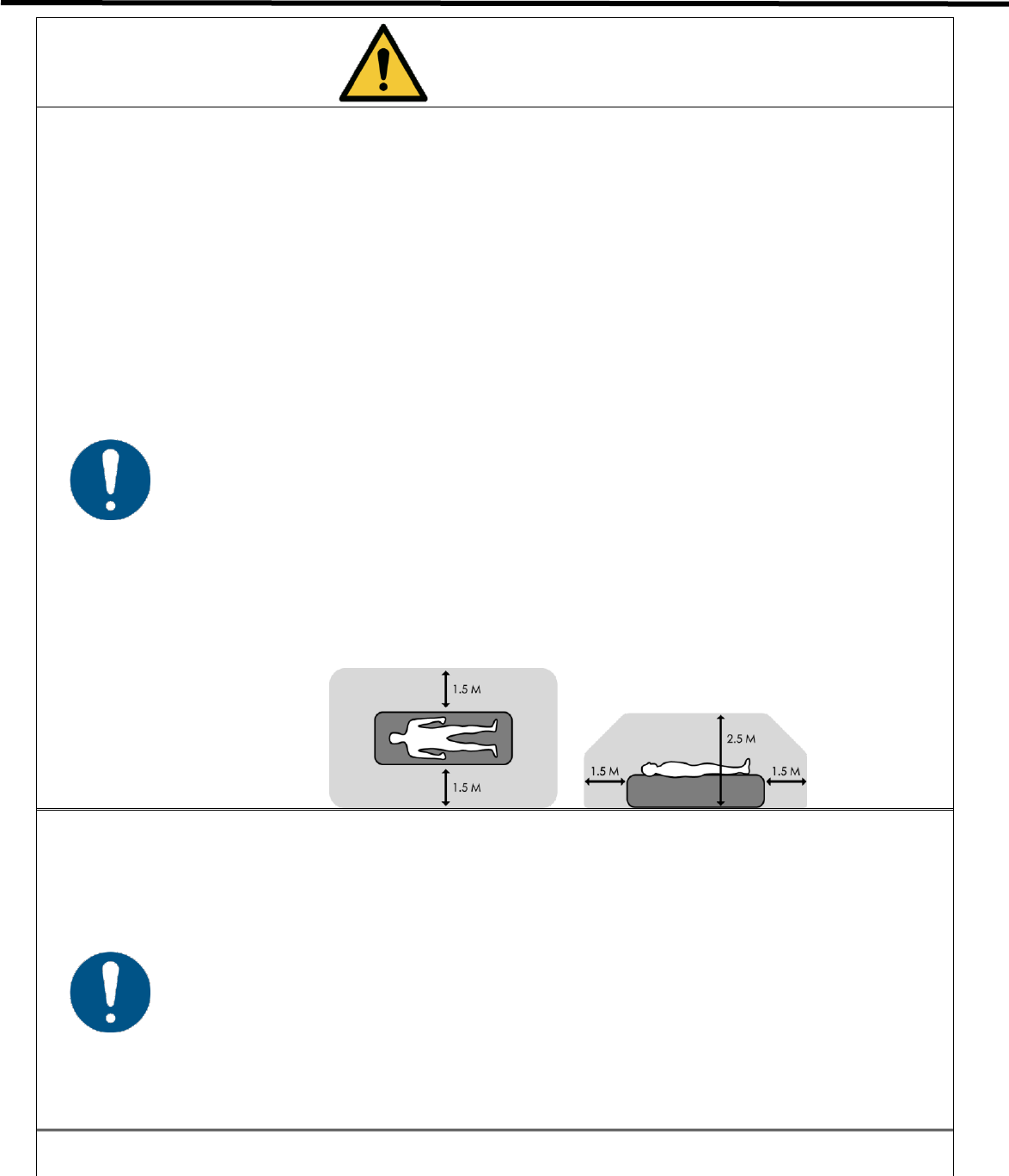
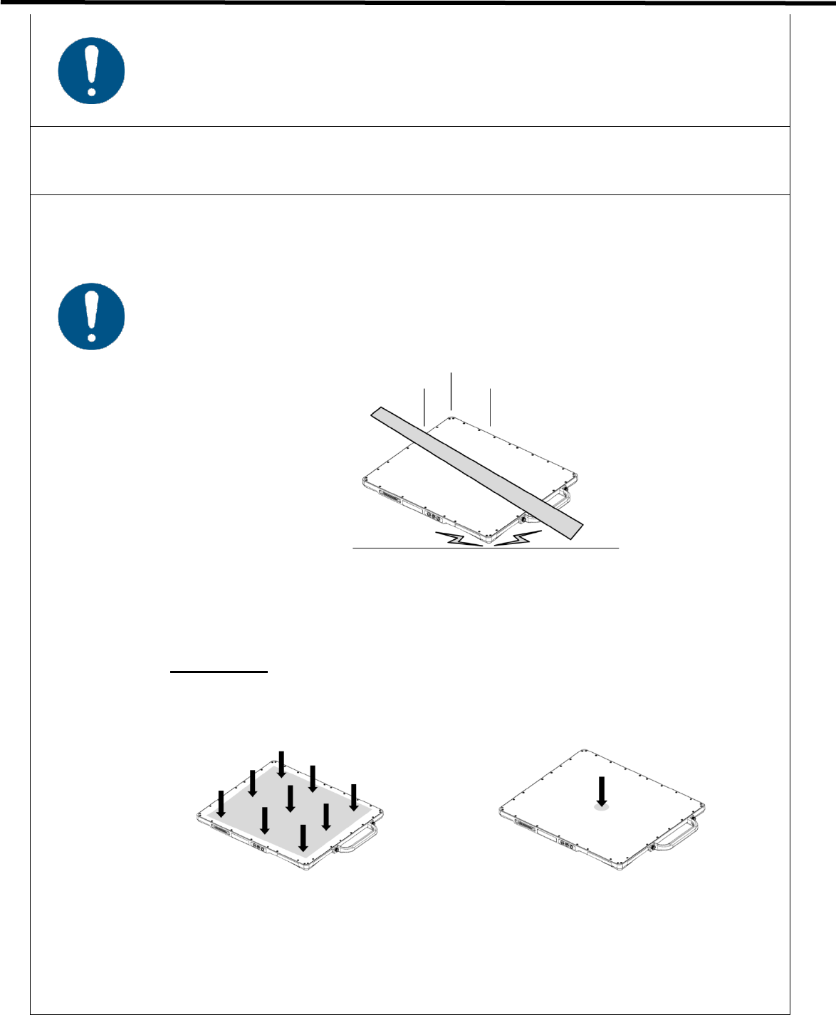
- Do not place excessive weight on the detector.
Otherwise, the internal image sensor may be damaged.
<Load Limit>
Uniform load: 150 kg over the whole
area of the detector
Local load: 100 kg on an area
of 40 mm in diameter
- Be sure to use the detector on a flat surface that does not bend.
Otherwise, the internal image sensor can be damaged.
- Be sure to securely hold the detector while using it in upright positions.
Otherwise, the detector may fall over, resulting in injury to the user or patient, or
may flip over, resulting in damage to the inner device.

EVS 2430W User’s Manual 1. Safety Information
DRT-MAN-091 13
1.2. Notes for using the equipment
When using the equipment, take the following precautions. Otherwise, problems may occur and the equipment may
not function correctly.
System Diagnostic
• The Ecali1 software runs a system diagnosis.
• Run Ecali1 software after installing the system, at least once a year. If an error occurs, report the detailed error
information to DRTECH local dealer or distributor.
Calibration
• To ensure optimal performance of the system, it is important to verify that the system is calibrated.
• You can process calibration with the calibration data CD (provided).
Before exposure
• Be sure to check the equipment on a daily basis and confirm that it works properly.
• Suddenly heating the room in clod area will cause condensation to form on the equipment. In this case, wait until
the condensation evaproates before performing an exposure. If the equipment is used while the condensation
forms, problems may occur in the quality of captured images. When an air-conditioner is used, be sure to
raise/lower the temperature gradually so that a significant change in temperature in the room and in the
equipment does not occur, to prevent condensation.
CAUTION
The owner is responsible for ensuring that the system diagnostic is
performed every year.
Do not try to use the system if the system diagnosis failed.
CAUTION
The owner is responsible for ensuring that the system calibration is
performed whenever the system installation is completed or the system is
repaired. Do not try to use the system if system calibration is not
performed.

EVS 2430W User’s Manual 1. Safety Information
DRT-MAN-091 14
During exposure
• Do not use the selected frequency chanel (2.4GHz and 5GHz dual band) for other wireless devices.
Mutual interference may affect the image data transmission rate.
• Do not use the detector near devices generating a strong magnetic field. Doing so may produce image noise or
artifacts.
Image Backup
• To avoid missing images which might result in patient being exposed to additional doses of radiation, it is
important to send the images to PACS or back up the images by filming or by using external storage devices
such as CD, DVD, HDD, USB, etc.. This should be done as a routine operation for every patient. If the hard disk
of your workstation is about to full, the operator should backup images and manually delete the images as
administrator to make room on the hard disk for new images.
User Limitation
• The Ecali1 software has the technician mode which could only be operated by inputting the correct PASSWORD.
The technician mode should be operated by the personnel who are qualified by DRTECH.
Electric Shock Hazards
• To reduce electric shock hazards, the system must be connected to an electrical ground.
• A three-contact conductor AC power cable is supplied with this system to provide the proper electrical grounding.
The power cable must be plugged into an UL-approved three-contact electrical outlet.
• Do not disassemble or modify the product as it may result in fire or electric There are no serviceable parts inside
equipments and adjustments should not be made. Only trained and qualified personnel should be permitted
access to the internal parts of the system.
• To reduce electric shock hazards, product is required to be well insulated with the use of appliance coupler, mains
plug, and other seperable connections.

EVS 2430W User’s Manual 1. Safety Information
DRT-MAN-091 15
Disinfection and cleaning
• Wipe it with a dry cloth slightly damed with a neutral detergent.
• Do not use solvents such as alcohol, thinner or benzene. Doing so may damge the surface of the equipment.
• Do not clean the system while the power is on.
Operating/storage environment
• Be sure to use and store this equipment under the conditions described below:
Temperature
Humidity
Atmospheric pressure
Operating environment
10 to 35 ℃
30 to 85 % RH
700 to 1060 hPa
Transportation &
Storage environment
-10 to 40 ℃
5 to 95 % RH
500 to 1060 hPa
• Do not expose this equipment to high temperatures and/or high humidity. Malfunction can occur.
• When not in use, keep the detector, handle unit, and grid in a designated location or in a location where they are
safe and cannot fall down.
Notes on disposal
• Disposal of this product in an unlawful manner may have a negative impact on health and on the environment.
Therefore, when disposing this product, be absolutely sure to follow the procedure which complies with the laws
and regulations applicable in your area.
• The expected life span of EVS 2430W system is about 3 years.
Handling the equipment
• The equipment must be handled with care to avoid personel injury or damage to the internal image sensor.
• The EVS 2430W Wireless is an advanced wireless digital radiographic equipment in the DRTECH Exprimer
series. This equipment is designed to provide the highest resolution and sensitivity in the series. In addition, the
wireless LAN (IEEE 802.11n*) communication feature improves the operability, and high-speed processing.

EVS 2430W User’s Manual 2. Introduction
DRT-MAN-091 16
2. Introduction
2.1. Features
• Wireless LAN communication (IEEE 802.11n*) includes a lightweight and thin detector that is easy to handle.
• The shape of the detector, which is identical to that of a conventional film cassette complying with ISO4090,
enables digital radiography to apply to the existing analog radiography configuration.
• The new sensor with 76 μm of pixel pitch and CsI (Cesium Iodide), Gadox (Gadolinium Oxysulfide) used for the
scintillator produces high resolution (approx. 11.8 Mega pixels) digital images within the effective imaging area
(223 x 291 mm), with low doses of X-rays.
• Depending on the operating conditions at each site, the wiring unit (optional) enables the equipment to be used
through expansion to a wired connection.
At the time of installation, set a specific channel in the frequency band of 5.0 GHz before using the LAN.
Note that the available frequency band for this standard varies, depending on the local radio laws,
regulations and system requirements.
2.2. Application specification
Intended medical indication
The EVS 2430W Digital X-ray detector is designed for digital imaging solution, for providing general
radiographic diagnosis of human anatomy. This device is intended to replace film or screen based radiographic
systems in all general purpose diagnostic procedures. This device is not intended for mammography
applications.
Intended patient population
Considerations
Requirement description
Age
neonatal to geriatric
Health
Not relevant
Nationality
Multiple
Sex
Not relevant
Patient state
Patient is user
Patient is not user
Patient is not
user
Not relevant, unless patient is agitated

EVS 2430W User’s Manual 2. Introduction
DRT-MAN-091 17
Intended part of the body or type of tissue applied to or interacted with
1) Measurement site : body
2) Condition : Intact or wund skin
Intended user profile(Operator Profile)
Considerations
Requirement description
Education
Minimum
- At least graduate of radiology college
Maximum
- No maximum
Knowledge
Minimum
- Read and understand 'westernized Arabic' numerals when
written in Arial font
- Can distinguish of human body
- Understands hygiene
Maximum
- No maximum
Language understanding
Minimum
- Local language
Maximum
- Understanding of manual that is writing in English
Experience
Minimum
- Physician or legally certified operator
Maximum
- No maximum
Permissible impairments
Minimum
- Mild reading vision impairment or vision corrected to log MAR
0.2
- Average degree of aging-related short term memory
impairment
- Impaired by 40 % resulting in 60 % of normal hearing at 500
Hz to 2 kHz

EVS 2430W User’s Manual 2. Introduction
DRT-MAN-091 18
Intended conditions of use
Considerations
Condition
Environment including hygienic requirements
Operating conditions
- Temperature: +10 ºC to +35 ºC
- Barometric Pressure: 700 hPa to 1060 hPa
- Humidity: 30 % R.H. to 85 % R.H.
Storage and delivery conditions
- Temperature: -10 ºC to +40 ºC
- Barometric Pressure: 500 hPa to 1060 hPa
- Humidity: 5 % R.H. to 95 % R.H.
Non-sterile
Multiple patient use
Less than ten minute contact
Indoor use only
Ambient luminance range: 100 lx to 1500 lx
Viewing angle: normal to the display ± 20°
Frequency of use
Reusable
1 day: 200 shot
Location
In hospital environment
Mobility
Portable ME equipment to be used on a
patient
EVS 2430W User’s Manual 2. Introduction
DRT-MAN-091 19
2.3. System Configuration
2.3.1. Basic Configuration
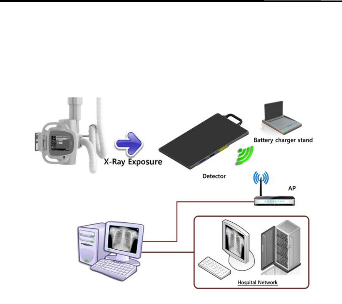
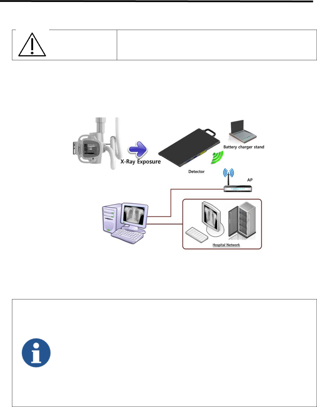
Generally, the EVS 2430W detector is used in system configuration as illustrated below:
Figure 2.1 EVS 2430W System Configuration
EVS 2430W User’s Manual 2. Introduction
DRT-MAN-091 20
Wireless Connection
• EVS 2430W wireless detector transmits images and data by wireless communication.
• A battery pack should be installed in the detector to use it under the wireless configuration.
• Up to 2 battery packs can be charged simultaneously from a battery charger.
- Use of multiple WLAN devices within the same frequency band may cause interference within
each wireless communication and slow down the transmission speed
- Do not cover or block the wireless module of the detector. Otherwise, the transmission speed or
operable distance may reduce.
- Recommended maximum operating distance of wireless communication, between the detector
and Access Point (AP), is 8 meters.
Wired Connection
• Connect EVS 2430W wireless detector and SCU / or Functional cable with a tether interface cable to make a
wired configuration.
• As the tether interface cable supplies power, a battery pack is not needed to be inserted in the detector.
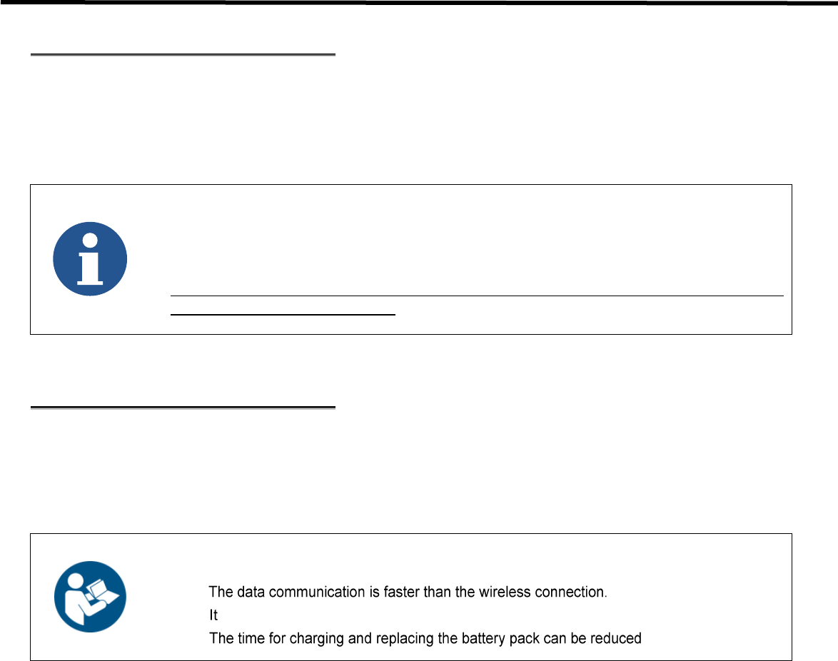
The wired connection is more suitable for stabilized communication when the detector is set in a
bucky stand or on a table.
enables the battery pack to be continously supplied with power while using the detector.
drastically.
EVS 2430W User’s Manual 2. Introduction
DRT-MAN-091 21
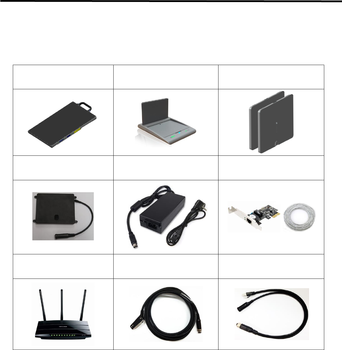
EVS 2430W Wireless system consists of detector, system synchronization unit (SSU), CDs and relevant accessories.
(Refer to chapter 3-1 “Product Components” for CD information)
Table 2.1. EVS 2430W Packaging
X-ray Detector (EVS 2430W)
Battery Charger
(EVS-BCS)
Battery Pack
(EVS-MBP, EVS-MBP-Y)
Wireless Charging System
: Optional
Power adaptor (12V, 7.08A)
+ AC Power Cable(2m)
LAN Card(PCIe Giga-bit LAN)
LAN Cable (CAT.7, 15m)
Access Point
(TP-LINK TL-WDR4300)
Tether Interface(3m)
: Optional
Functional cable (0.5 m)
+ Power Adaptor: Optional
EVS 2430W User’s Manual 2. Introduction
DRT-MAN-091 22
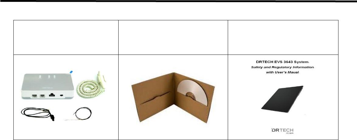
USB Switch Box Options
- USB Switch Box
- Hand Switch
- USB Cable(1m)
- Generator Cable(1.2m)
CD(Software / Calibration)
User’s Manual (Hard Copy)

EVS 2430W User’s Manual 3. Production Description
DRT-MAN-091 23
3. Product Description
3.1. Product Components
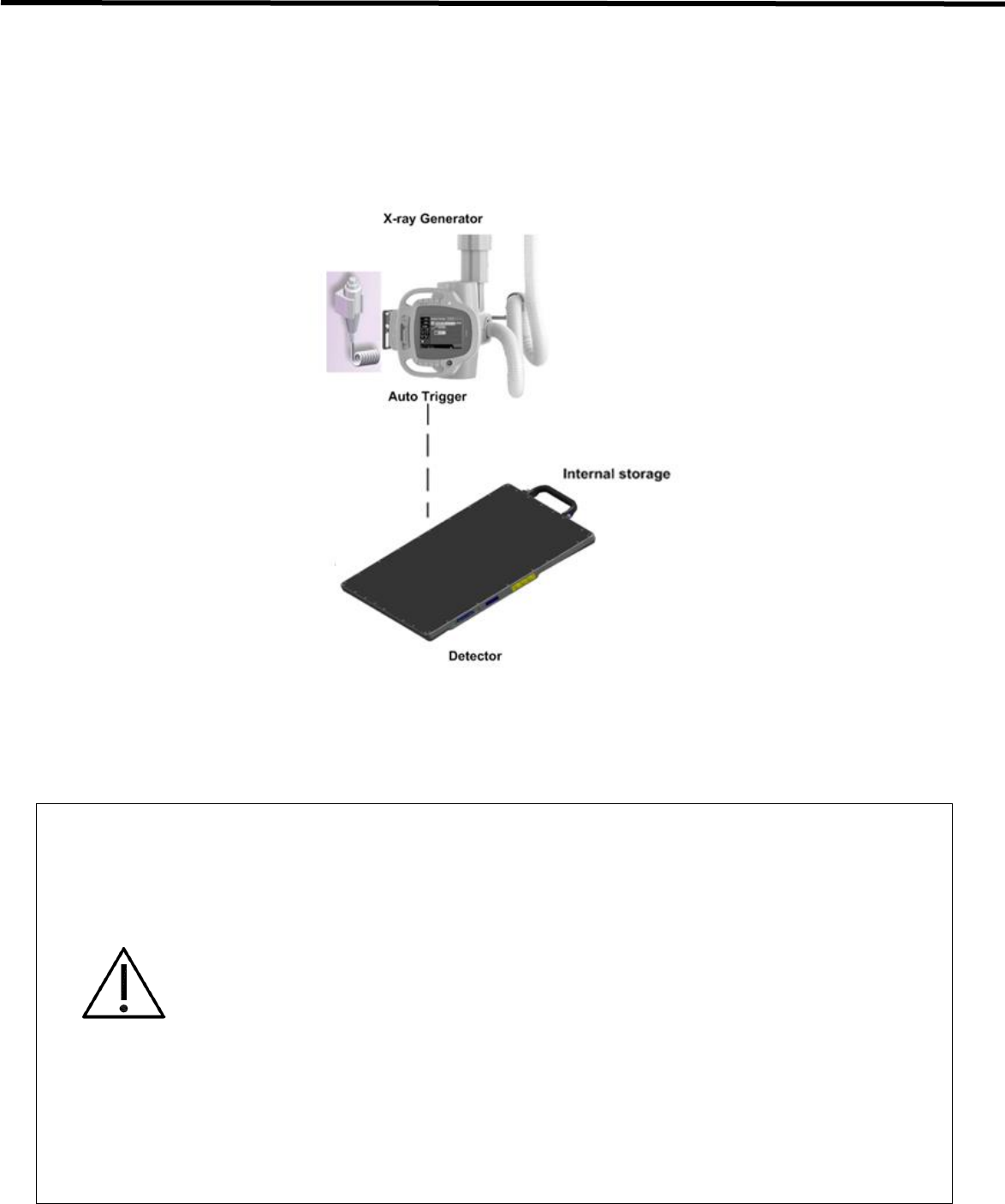
3.1.1. Auto Trigger Mode (AT Mode)
Table 3.1. Product componets for Auto Trigger Mode
Part name
Remark
Flat panel detector
EVS 2430W(Scintillator : CsI : Tl) 1.9 kg
EVS 2430GW(Scintillator : Gadox) 1.9 kg
Battery charger
EVS-BCS : 0.5 kg
Battery pack
EVS-MBP, EVS-MBP-Y : 0.24 kg
Wireless Charging System
EVS-WPCS : 0.15 kg
CD (Software / Calibration)
Document : User ‘s Manual (PDF)
Calibration Data : MAP, PMP, GMP
Software : Econsole1, Ecali1
User’s Manual
Supported in all Modes
License Dongle Key (USB)
Needed for activating Econsole1
Tether Interface Cable (3m)
Supported in all Modes
LAN Cable (15m)
Supported in all Modes
AC Power Cable (2m)
Supported in all Modes
WARNING
The use of accessories and cables other than those specified, with the exception of EVS 2430W Wireless
accessories and cables sold by DRTECH Co., LTD. as replacement parts for internal components, may result in
increased emissions or decreased immunity of the equipment. Accessory equipment connected to the analog and
digital interfaces must be certified according to the respective IEC standards. All combinations of equipment must be
in compliance with IEC 60601-1-1 system requirements. Any person who connects additional equipment to the signal
input or signal output ports configures a medical system, and is therefore responsible for ensuring that the system
complies with the requirements of the system standard IEC 60601-1. If in doubt, consult DRTECH technical support
representative.

EVS 2430W User’s Manual 3. Production Description
DRT-MAN-091 24
3.1.2. Synchronization Trigger Mode (Sync. Mode)
Table 3.2. Product componets for Synchronization Trigger Mode
Part name
Remark
Flat panel detector
EVS 2430W(Scintillator : CsI : Tl) 1.9 kg
EVS 2430GW(Scintillator : Gadox) 1.9 kg
Battery charger
EVS-BCS : 0.5 kg
Battery pack
EVS-MBP, EVS-MBP-Y : 0.24 kg
Wireless Charging System
EVS-WPCS : 0.15 kg
CD (Software / Calibration)
Document : User ‘s Manual (PDF)
Calibration Data : MAP, PMP, GMP
Software : Econsole1, Ecali1
User’s Manual
Supported in all Modes
License Dongle Key (USB)
Needed for activating Econsole1
Tether Interface Cable (3m)
Supported in all Modes
LAN Cable (15m)
Supported in all Modes
AC Power Cable (2m)
Supported in all Modes
Generator Cable (15m)
Supported in Sync. Mode

EVS 2430W User’s Manual 3. Production Description
DRT-MAN-091 25
3.1.3. USB SW Mode
Table 3.3. Product componets for USB SW Mode
Part name
Remark
Flat panel detector
EVS 2430W(Scintillator : CsI : Tl) 1.9 kg
EVS 2430GW(Scintillator : Gadox) 1.9 kg
Battery charger
EVS-BCS : 0.5 kg
Battery pack
EVS-MBP, EVS-MBP-Y : 0.24 kg
Wireless Charging System
EVS-WPCS : 0.15 kg
USB Switch Box
EVS-USB01
Supported in USB Mode
CD (Software / Calibration)
Document : User ‘s Manual (PDF)
Calibration Data : MAP, PMP, GMP
Software : Econsole1, Ecali1
User’s Manual
Supported in all Mode
License Dongle Key (USB)
Need for Econsole1
Hand Switch
Supported USB Mode
Tether Interface Cable (3m)
Supported in all Modes
Extension Tether Cable (7m)
Supported in all Modes
LAN Cable (15m)
Supported in all Modes
AC Power Cable (2m)
Supported in all Modes
USB Cable (1m)
Supported in USB Mode
X-ray Cable (3m)
Supported in USB Mode

EVS 2430W User’s Manual 3. Production Description
DRT-MAN-091 26
3.1.4. Workstation (Recommended and minimum but NOT included)
Table 3.4. Workstation
Item
Specification
Operating system
Windows 7 64 bit SP1 (Professional Edition or higher)
CPU
Intel Core i5 2600 or higher (or compatible CPU)
Memory
4GB or higher
Hard disk
1TB or higher
LAN card
Gigabit (Detector only)
Intel® PRO 1000 Series (Gigabit LAN Card for network interface) Min.
Requirements : 1Gbps
Jumbo Frames : 9K
Receive Descriptors : 2K (higher than 1024)
This is not dedicated to DICOM
Monitor
1024 x 768 or higher
Optional disc drive
CD or DVD R/W
3.1.5. Grid (Recommended but Not included)
Table 3.5. Grid specifications
Item
Description
SID
100 / 130 / 150 / 180 cm
Ratio
10 : 1
Frequency
125 Line/inch
Inter spacer
Al

EVS 2430W User’s Manual 3. Production Description
DRT-MAN-091 27
3.2. X-ray Imaging Condition
• X-ray Energy Range
40kVp to 150kVp
• Reliability (Lifetime Dose)
More than 74Gy (35uGy x 365days x 24hours x 60minutes x 60seconds/15sec)

EVS 2430W User’s Manual 4. Components and Specifications
DRT-MAN-091 28
4. Components and Specifications
4.1. Detector
4.1.1. Detector Specification
Table 4.1. Detector Specifications
Item
Description
Model
EVS 2430W / EVS 2430GW
Purpose
General Radiography
Pixel Pitch
76 ɥm
Scintillator
CsI (Cesium Iodide) / Gadox (Gadolinium Oxysulfide)
Image Matrix Size
3072 × 3840 pixels
Effective Imaging Area (H x V)
233 x 291 mm
Image Acquisition and Transfer Time
< 8 sec.
Rated Power Supply
Wireless (Maker/Mode name/Rating)
Wired (Maker/Model name/Rating)
Powered by the battery pack
(DRTECH Corporation(Powerlinx) / EVS-MBP, EVS-MBP-Y
/7.4V, 4000 mAh)
Powered by Power adopter using tether interface
(XP Power / AHM85PS12 / DC12V 7.08A)
Power Consumption
Max. 24 W
Network Interface
Gigabit
Dimensions (㎜) [±0.5 mm]
267.5 (H) × 327.5 (V) × 14.9 (D)
Weight
1.9 kg
Environmental Requirements
Operational
Temperature: +10 to +35℃
Humidity: 30 to 85% RH (Without Condensing)
Atmospheric pressure: 700 to 1060 hPa
Storage and Transportation(unpacked)
Temperature: -10 to +40℃
Humidity: 10 to 90% (Without Condensing)
Atmospheric pressure: 500 to 1060 hPa
†Tether Interface:
Allows the detector to communicate with SSU via Ethernet cabling when wireless communications is not available or
when higher speed data transfer is necessary
EVS 2430W User’s Manual 4. Components and Specifications
DRT-MAN-091 29
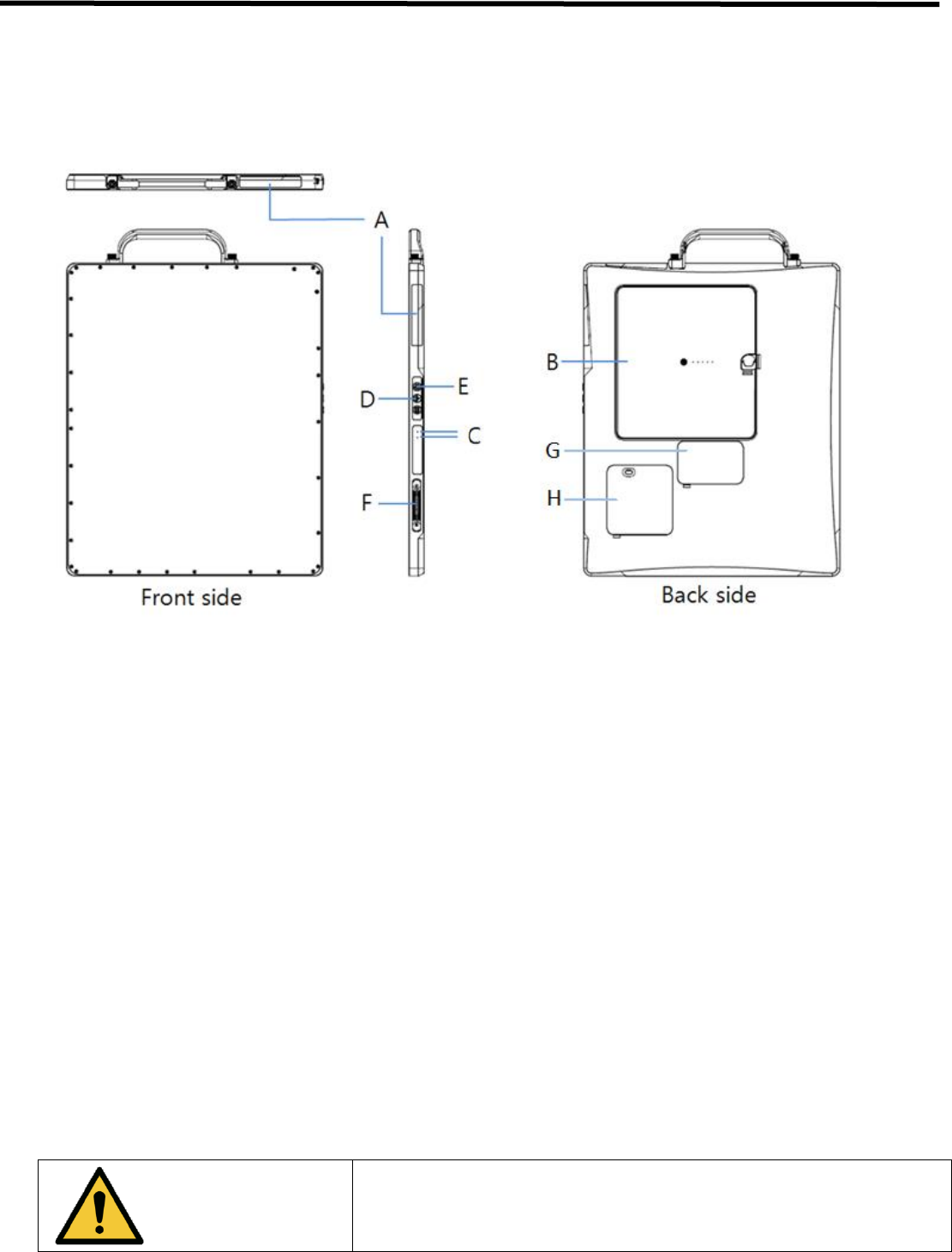
4.1.2. Detector Component
The detector is designed to capture radiographic images.
Captured images are transmitted to the EVS 2430W image-capture computer using the wireless/wired data transfer
Figure 4.1. Detector Components
A. Wireless antena : Transmits image data with wireless comunication (IEEE802.11n).
B. Battery Pack : Supplies electrical power to the detector while using wireless communication
C. Satatus indicators
• Power : Shows power on/off status of the detector.
• Ready : Shows data communication status and ready status of detector
(Lights on indicates that detector is busy, lights off means detector is ready)
• Link : Shows detector’s registraion and connection status.
• AP : Lamp indicating Wired/ Wireless mode (2.4 GHz / 5 Hz)
D. AP Button: Can register detector among different wireless connection options.
(Connection options: Wireless using AP/ Wireless using detector’s internal AP/ Portable mode)
E. Power Button : Turns Detector on / off
F. Connecter : Data communication and power supplying through tether cable
G. Debugging Cover
H. WPCS Window : Wireless Charging Rx Window
WARNING
Don’t remove G and H. if metal objects come into case, it can lead to
product malfunction..
The operator should not contact the inside of the access cover(G and H)
with the patient.
EVS 2430W User’s Manual 4. Components and Specifications
DRT-MAN-091 30
4.2. Battery Charger and Battery Pack and Adaptor
4.2.1. Battery Charger
4.2.1.1. Battery Charger Specifications
Table 4.2. Battery Charger Specifications
Item
Description
Model
EVS-BCS
Simultaneous Charging
Battery Pack 2 EA
Charging Time
3 hours
Rated Power Supply
DC +12 V, 6 A Max.
Dimensions (W x H x D)
180 mm x 255 mm x 35 mm
Weight
0.5 kg
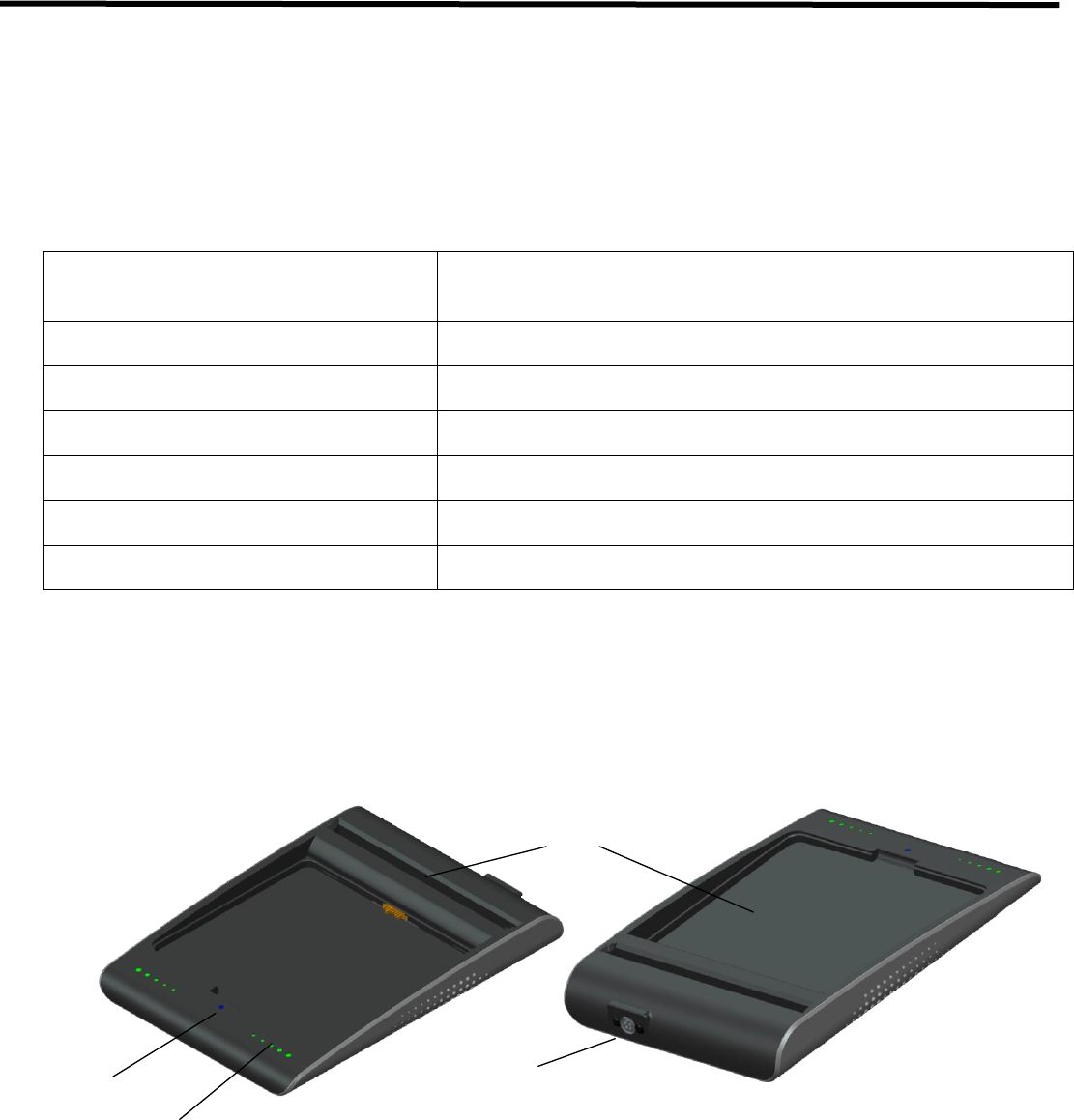
4.2.1.2. Battery Charger Components
A
B
D
C
Figure 4.2. Battery Charger
A. Power indicator : Indicates the power on/off status..
B. Charging indicator : Indicates the charging status.
C. Battery compartment : Insert the battery pack to charge.
D. DC Input : Connect the DC adapter to supply electrical power to the battery charger

EVS 2430W User’s Manual 4. Components and Specifications
DRT-MAN-091 31
4.2.2. Battery Pack
4.2.2.1. Battery Pack Specification
Table 4.3. Battery Pack Specifications
Item
Description
Model
EVS-MBP, EVS-MBP-Y
Cell Type
Lithium Polymer
Number of Cells
2S1P (2series 1 Parallel)
Rated Power Supply
Output : DC +7.4 V
Lifetime
Approx. 500 cycles of use (full charge to discharge is 1 cycle)
Dimensions (W x H x D)
163 mm x 148 mm x 7 mm
Weight
0.24 kg
4.2.2.2. Battery Pack Components
A
B
Figure 4.3. Battery Pack
A. Charging indicator : Indicates the charging status
B. Latch knob : Rotate between on/off for battery swap
EVS 2430W User’s Manual 4. Components and Specifications
DRT-MAN-091 32
4.2.2.3. Charging Battery Pack
The battery pack supplies power to the detector during wireless connection.
Be sure to use only the dedicated battery pack, and fully charge it before usage.
• Connect the power adapter to the DC Input port of the battery charger. The power LED lights in blue indicates the
presence of direct current (DC) power.
• Insert the battery pack into the battery charger. Charging starts automatically. The charge LED lights appear
green when the battery pack is being charged. When battery pack is completely charged, all levels of chare LEDs
will illuminate.
• Gently pull the charged battery pack to remove from the battery charger.
WARNING
Securely plug the power cord into the power source. If contact failure
occurs, or if dust or metal objects come into contact with the exposed metal
prongs of the plug, fire or electrical shock may occur.
CAUTION
Be sure to stop charging the battery pack when the charge LED lights
appear in green beyond the specified charging time. Not doing so may result
in battery pack overheating or smoke emission, or battery explosion or fire.
CAUTION
You must use the power adaptor that is certified with IEC 60950 or IEC
60601-1.
Two batteries can be charged at the same time.
It takes approximately two hours to fully charge a battery pack. The required
charging time may vary depending on the temperature and remaining
battery level.

EVS 2430W User’s Manual 4. Components and Specifications
DRT-MAN-091 33
4.2.3. Adaptor
Table 4.3. AD/DC Adaptor Specifications
Item
Description
Model
AHM85PS12
Rated input
100- 240Vac / 1.0A, 50/60Hz
Rated output
12V, 7.08A
Maker
XP POWER
4.3. Wireless Charging System
4.3.1. EVS-WPCS
4.3.1.1. EVS-WPCS Specifications
Table 4.4. EVS-WPCS Specifications
Item
Description
Note
Model
EVS-WPCS
Dimensions (W x H x D)
115.8 mm x 94.8 mm x 12 mm
Weight
0.15 kg
Charging Transceiver IC
Freescale MWTC1012
Medium Power
Charging Receiver IC
Freescale MWPR1516
Medium Power
Tx Coil to Rx Coil
3mm
Input Voltage
DC 12V (±1%) / more than 3A or
Adaptor (XP Power / AHM85PS12 /
DC12V 7.08A)
Tx Module Input
Output Power
DC 10V /1.4A (14W)
Rx Module Output
Standby Current/Power
27.22mA / 326.6mW
Max Power Efficiency
83.2%
Storage Temperature
-20℃ to 85℃
Operating Temperature
10℃ to 35℃
WPC Qi Specification
WPC MP-A2 Standard.
H/W & S/W Protection Algorism.
EVS 2430W User’s Manual 4. Components and Specifications
DRT-MAN-091 34
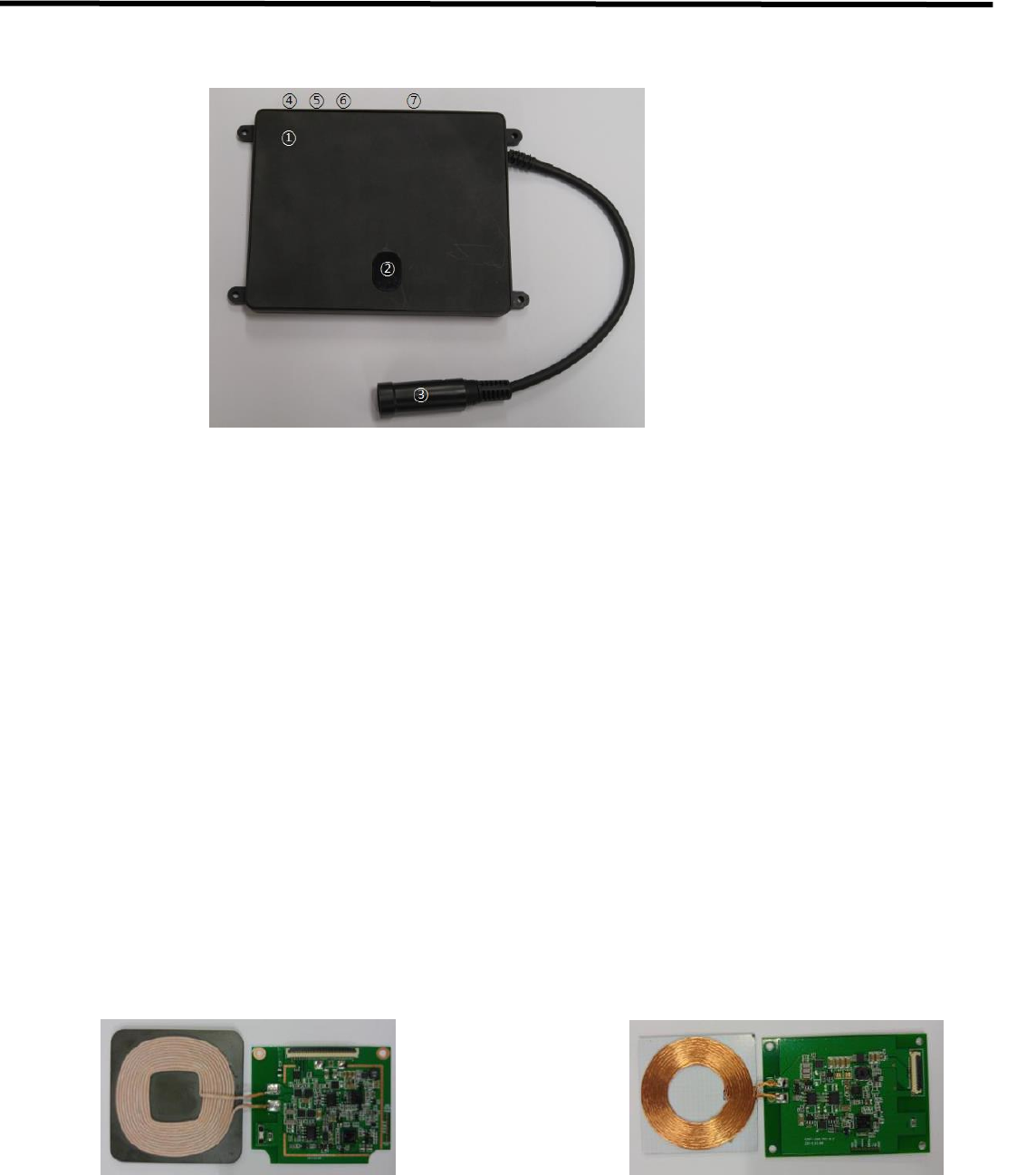
4.3.1.2. EVS-WPCS Components
Figure 4.4. EVS-WPCS
1. EVS-WPCS Base
2. IRDA Window : IRDA comunication window.
3. Power Connection Cable
4. Debug Connector : for debuging
5. ID Switch : Deivce id setting dip switch.
6. Indicate LED Conntor : for cradle (Option)
7. Indicate LED Conntor : for system (Option)
4.3.1.3. TX / RX Module Specification
+ Tx Module
- PCB size : 55(mm)x45.5(mm)
- Coil size : 52.5(mm)x52.5(mm)
- Coil inductance : 11.7uH (MP A2)
+ Rx Module
- PCB size : 65(mm)x47(mm)
- Coil size : 45.6(mm)x45.6(mm)
- Coil inductance : 7.3uH
EVS 2430W User’s Manual 4. Components and Specifications
DRT-MAN-091 35
4.3.1.4. RX Module Components
1. RX Module Base
2. Ferrite Sheet
3. Coil
4. IRDA : Communication for EVS-WPCS.
5. Connector : Power Output Connector.
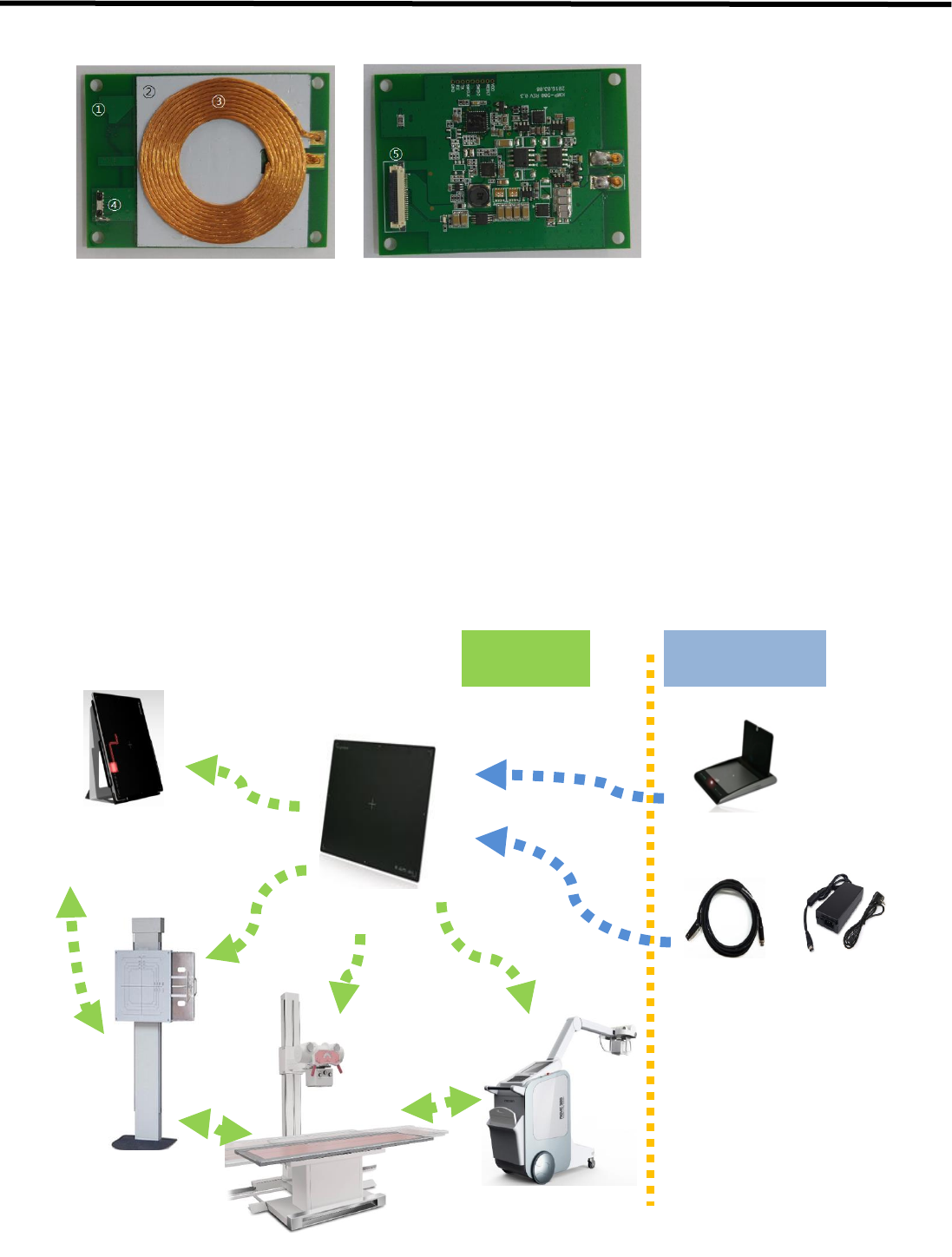
4.3.1.5. EVS-WPCS Operations
EVS-WPCS variety of supports for the charging form.
• Cradle Charging Type
• Stand or Bed Bucky Charging Type
• Mobile Charging Type
Cradle Carging
(Wall or Stand
Air State
(No Charging /
Using)
Stand Charging
Bed Table Charging
Mobile
WPCS Charging
Emergency Charging
Charger
Tether Cable + Power Adaptor
EVS 2430W User’s Manual 4. Components and Specifications
DRT-MAN-091 36
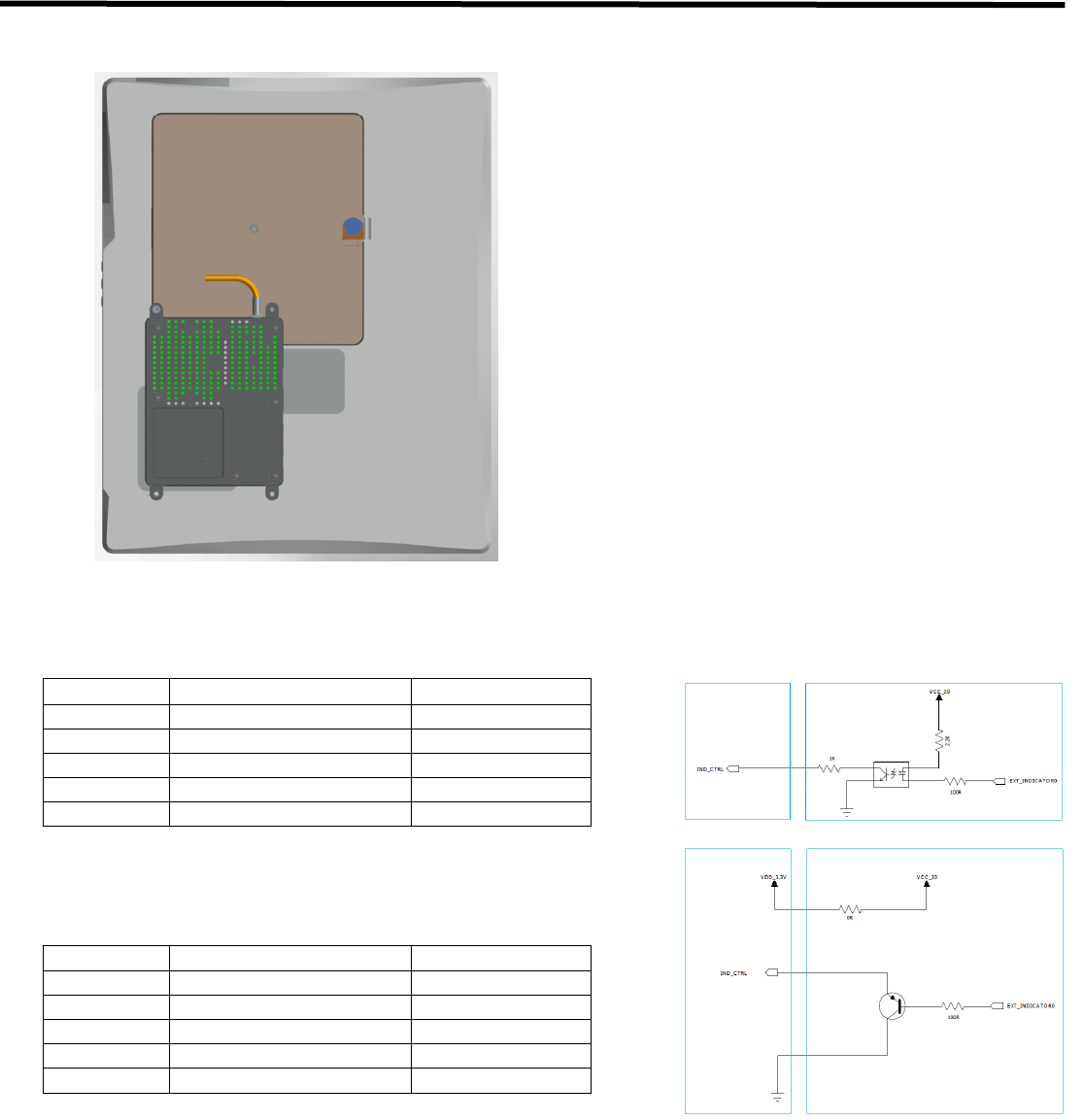
4.3.1.6. Attach Direction
4.3.1.7. Indicator LED Connector Description
Num.
Connector Name
Remark
1
3.3V
Power Out
2
Indicator Control 1
3
Indicator Control 2
4
Indicator Control 3
5
GND
4.3.1.8. Indicator LED Connector Description (Isolation)
Num.
Connector Name
Remark
1
Indicator Control 1
2
Indicator Control 2
3
Indicator Control 3
4
GND
5
GND
USER System EVS-WPCS

EVS 2430W User’s Manual 5. Operation Procedure
DRT-MAN-091 37
5. Operating Procedure
General Workflow
The following workflow indicates the procedures after startup of EConsole1 and other system equipments
5-1. Preparing to use the detector
5-2. Operating the detector
Attach a fully-charged battery pack to the detector.
2. Register1) the detector and make connection2) to the
EConsole1 power supply to the detector
1) : A procedure in order to register the detector
to a specific digital radiography system
2) : Network connection between the EVS 3643
wireless detector and the EConsole1
3. Conduct Examination
3) :ㆍ Selection of EVS 3643 wireless
from the Exprimer series detector
ㆍ Selection of wireless/wired
data transfer
ㆍSelect or register the patient information
ㆍSelect the protocol (selection3) of the detector)
- Arrange the patient in the correct posture
- Position the X-ray generator to adjust the
exposure field
- Check all the conditions
Check the captured images
ㆍ List the images
ㆍTransmit the images
Sterilize the portion of the detector that
has been in contact with a patient
5-3. Ending use of the detector
1. Turn off the detector
ㆍConduct the next examination
Loop back procedure
for each body part
Loop back procedure
for each patient
For details, refer to the
operation manual or
setup guide of the
EConsole1
2. Remove the battery pack
1. Turn on the detector
EVS 2430W User’s Manual 5. Operation Procedure
DRT-MAN-091 38
5.1. Preparing to Use the Detector
CAUTION
Be sure to use only the dedicated power supply for the EVS-2430W detector
5.1.1. Standard Configuration
Figure 5.1 EVS 2430W System Configuration
A. Wireless Connection
- EVS 2430W transmits images and data by wireless communication.
- A battery pack should be installed in the detector to use it under the wireless configuration.
- Up to 2 battery packs can be charged simultaneously from a battery charger.
B. Wired Connection
- Connect EVS 2430W and PC with a tether interface & Functional cable to make a wired
configuration.
- As the Functional cable supplies power, a battery pack is not needed to be installed in the
detector.
- Data communications are faster than wireless connection.
- It is able to keep charging a battery pack while using the detector.
EVS 2430W User’s Manual 5. Operation Procedure
DRT-MAN-091 39
5.1.2. Battery Pack
WARNING
Securely attach the battery into the detector or charger. If contact failure
occurs, or if dust or metal objects come into contact with the exposed
connector pins of the detector or charger, fire or electrical shock may occur
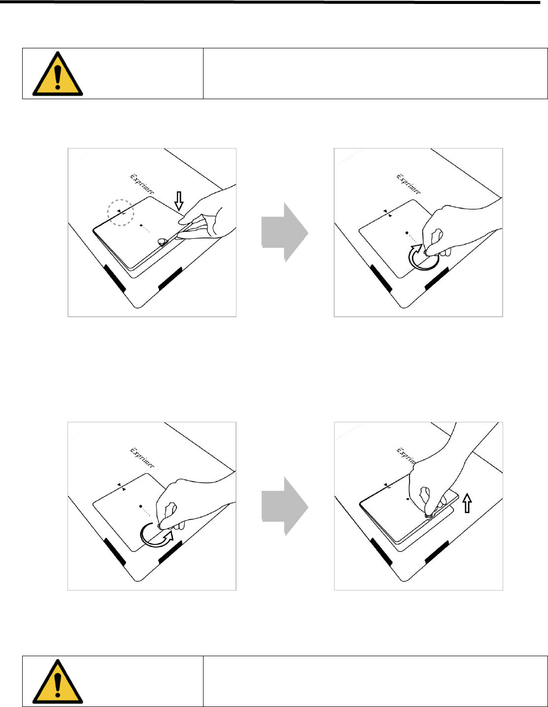
5.1.2.1. How to Attach a Battery Pack
1) Align the arrows on the detector and battery pack.
2) Push down the battery pack.
3) Turn the battery lock knob 90 degrees clockwise.
5.1.2.2. How to Detach a Battery Pack
1) Turn the battery lock knob 90 degrees anti-clockwise.
2) Pull up the battery pack grabbing the knob.
WARNING
Make sure to turn off the detector before detaching a battery pack. Press
and hold the power button for about 2 seconds. All status LED lamps turned
off indicates the detector is turned off.
EVS 2430W User’s Manual 5. Operation Procedure
DRT-MAN-091 40
5.1.2.3. How to Charge Battery Packs
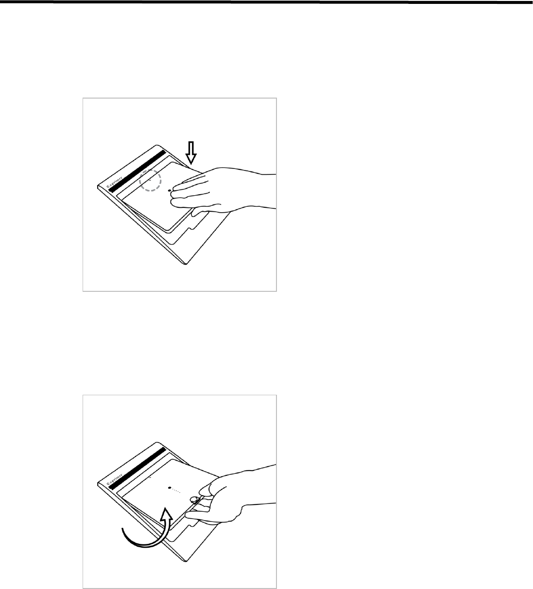
5.1.2.3.1. Horizontal Direction
5.1.2.3.1.1. Attachment
1) Align the arrows on the charger and battery pack.
2) Push down the battery pack.
5.1.2.3.1.2. Detachment
1) Put the finger into the groove on the charger and grab the battery pack.
2) Pull up the battery pack.
EVS 2430W User’s Manual 5. Operation Procedure
DRT-MAN-091 41
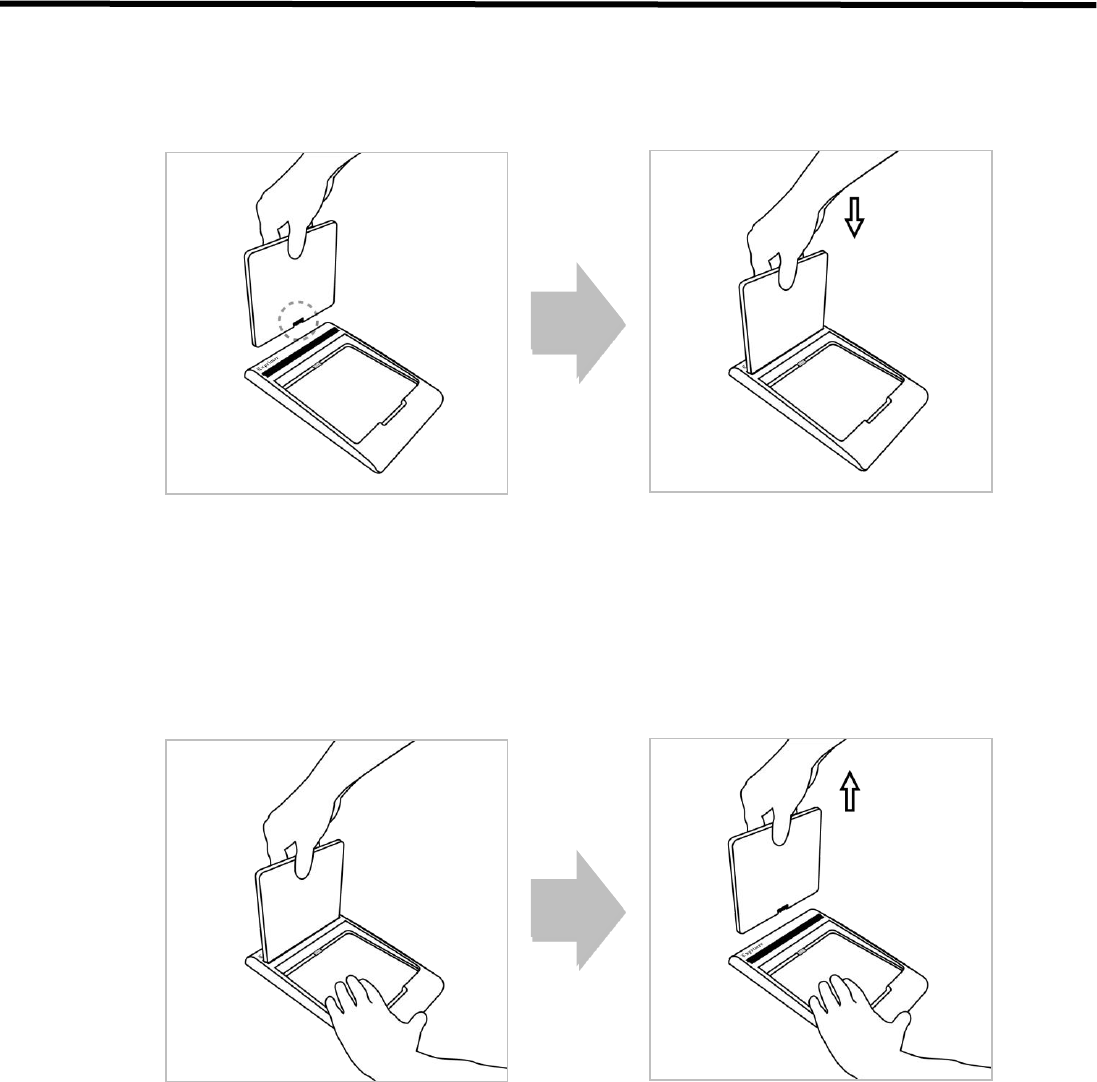
5.1.2.3.2. Vertical Direction
5.1.2.3.2.1. Attaching
1) Stand the battery pack up to reveal the battery charged connector.
2) Align the left and right side of battery pack to the charger.
3) Push down the battery pack.
5.1.2.3.2.2. Detaching
1) Grab the battery pack.
2) Pull up the battery pack and push down the charger.
EVS 2430W User’s Manual 5. Operation Procedure
DRT-MAN-091 42
5.2. Hardware Installation
5.2.1. Connecting Device
This section describes how to connect the EVS 2430W system (Detector)
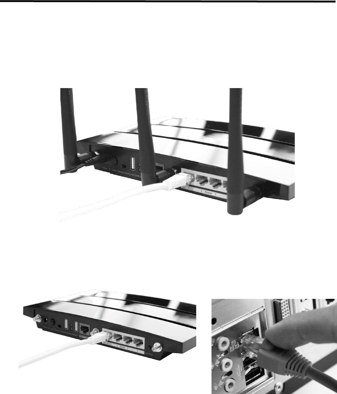
5.2.1.1. Operating AP
1) Connect the LAN cable to ethernet port (not internet) of AP, and the other to the LAN Card connector of
workstation assigned for the data transfer.
EVS 2430W User’s Manual 5. Operation Procedure
DRT-MAN-091 43
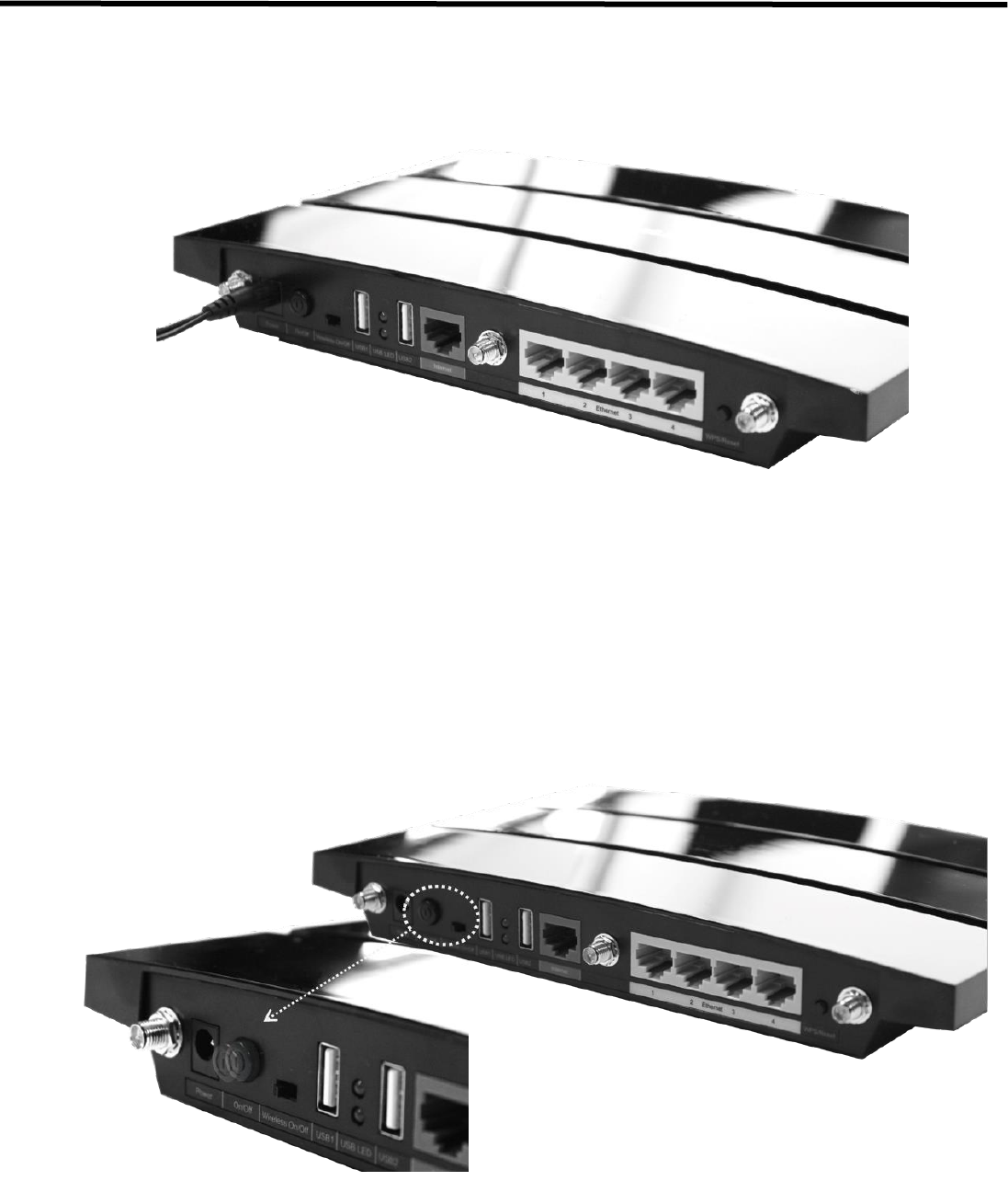
2) Connect the power cable to the power port of AP to supply power.
3) Turn on Wireless On/Off switch and push the Power button.
EVS 2430W User’s Manual 5. Operation Procedure
DRT-MAN-091 44
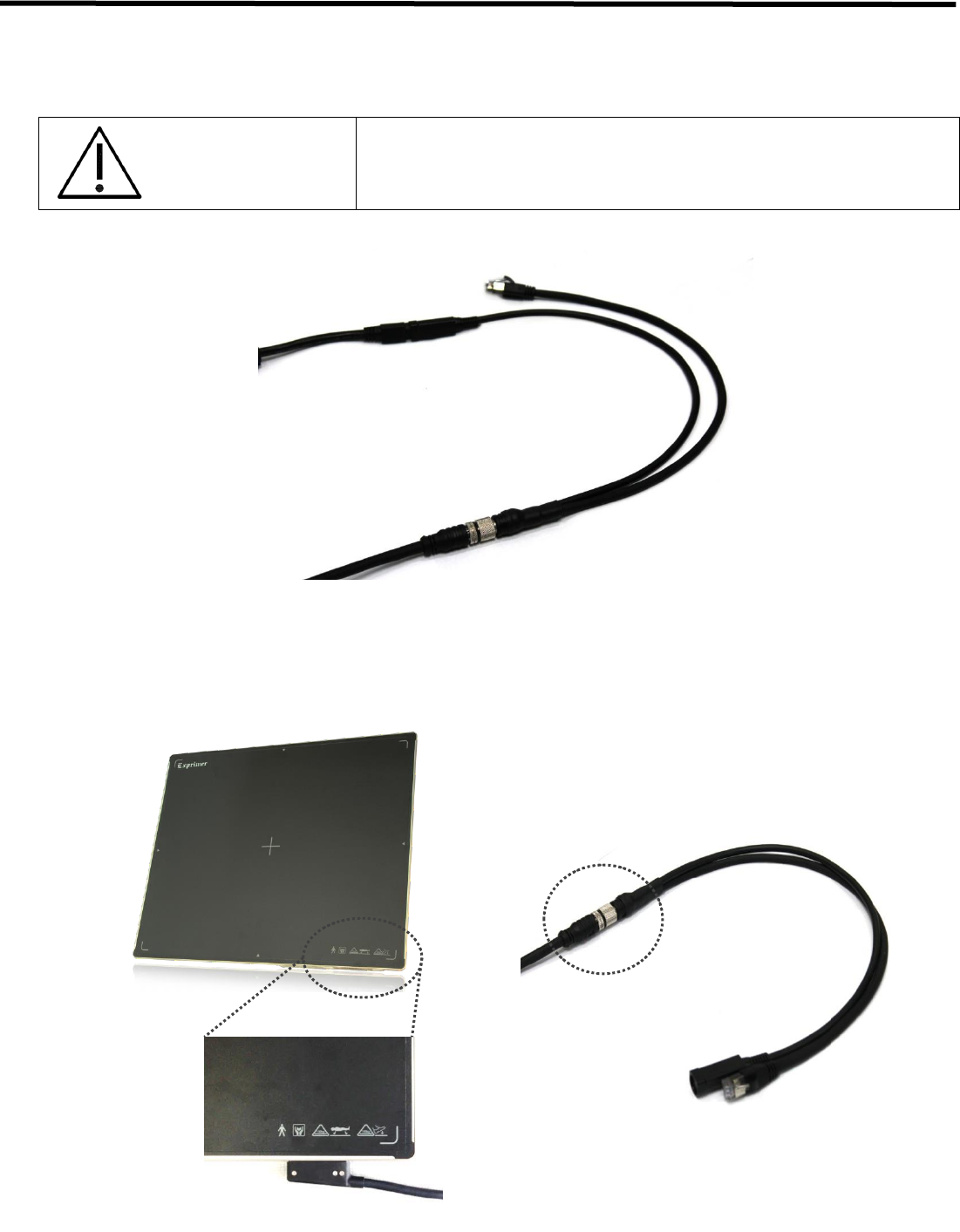
5.2.1.2. Functional Cable
This section describes how to connect the EVS 2430W system (Detector) without SSU by using functional cable.
CAUTION
Installation of this equipment should be made by licensed and authorized
personnel.
1) Connect the one of the functional cable to tether cable
Tether
Tether
Tether
Power
LAN
EVS 2430W User’s Manual 5. Operation Procedure
DRT-MAN-091 45
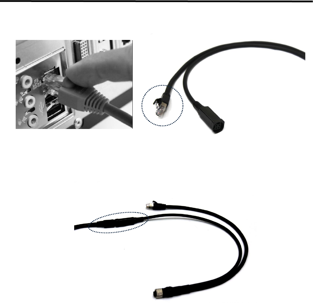
2) Connect the LAN cable to the LAN Card connector of workstation assigned for the data transfer
3) Connect the power cable to other side of functional cable to supply power
EVS 2430W User’s Manual 5. Operation Procedure
DRT-MAN-091 46
5.2.2. Operating Detector
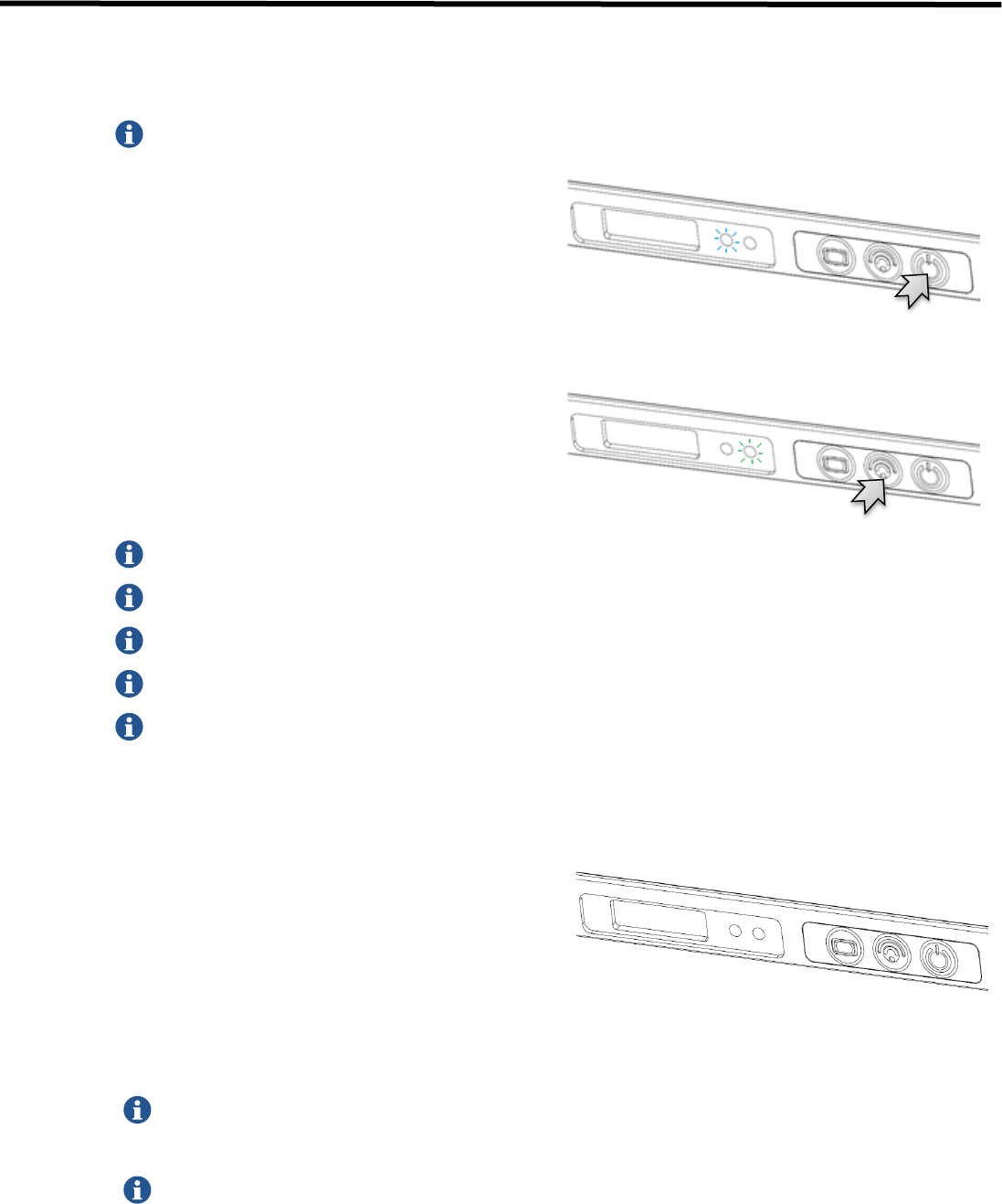
1) Turn on the detector
Before operating the detector, start up EConsole1
Press and hold the POWER button
(approx. 1 second )
Power lamp (Blue) lights up
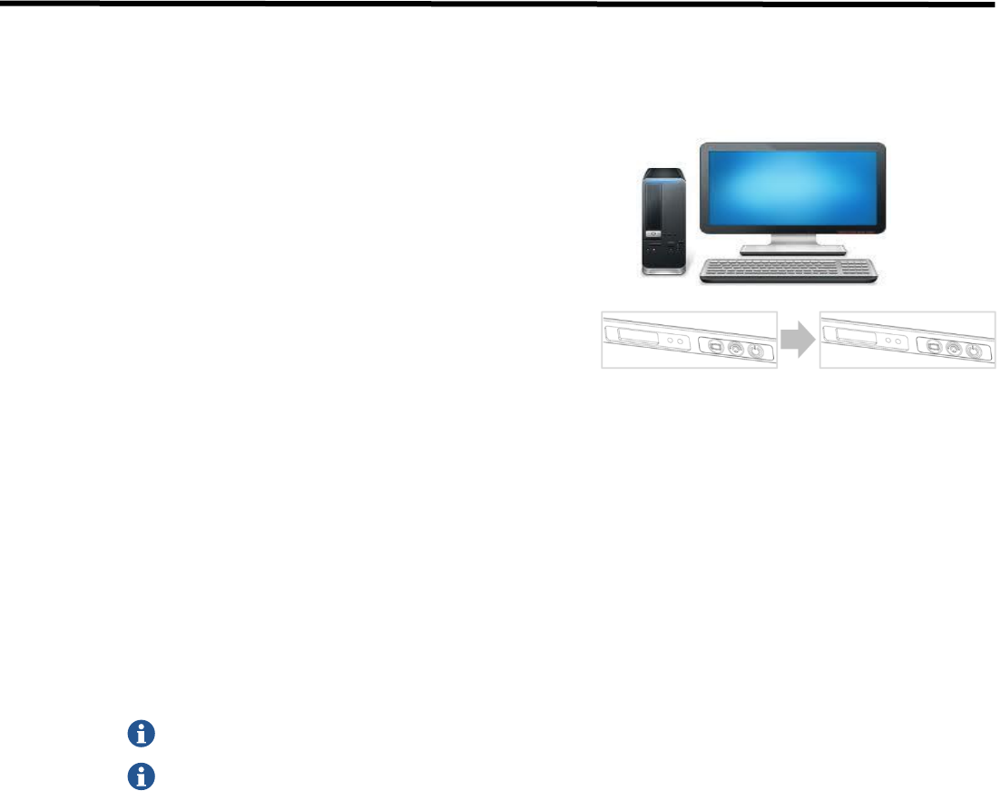
2) Register the detector and make connection to the EVS control system
i. Registration
AP lamp (Green) blinks
When the AP lamp is blinking 1 time in 2seconds, system is in wired mode status.
When the AP lamp is blinking 2 times in 2seconds, system is in wireless mode (AP_1) status.
When the AP lamp is blinking 3 times in 2seconds, system is in wireless mode (AP_1) status.
When the AP lamp is blinking 4 times in 2seconds, system is in wireless mode (detector AP) status.
When the AP lamp is blinking 6 times in 2sec, system is in wireless mode (portable mode) status.
**User can set value of AP_1, AP_2, in Ecali Program. Please refer to Operation Manual for Ecali1
(Calibration tool).
ii. Connection
Network connection between the internal wireless
module of the detector and the wireless access
point/EVS control system is secured automatically.
The link lamp lights up when the detector is
registered and the communication connection is
established.
The LINK lamp does not light up when the detector is not registered or the communication connection is
not established.
When the READY and AP lamp is blinking and LINK lamp does not light up, a communication error has
occurred.
Please refer to troubleshooting.
EVS 2430W User’s Manual 5. Operation Procedure
DRT-MAN-091 47
3) Conducting Examination
For details about operation, refer to the Operation Manual for the EConsole1.
i. Select the patient information or protocols
on the screen and start the examination.
The READY lamp (green color) lights up after
blinking 3 times when the detector and
EConsole1 change to exposure ready status.
• Arrange the patient in the correct posture and position the detector aligning it with the target body part.
• Position the X-ray generator to adjust the exposure field.
• Check all conditions before exposure.
Make sure that two lamps (POWER and LINK) are lit and AP lamp is blinking. This means that the system
is ready to start an examination.
A communication error has occurred when LINK lamp lights are off.
When the READY lamp (orange color) blinks slowly, the detector is in detector selection status (Sleep).
The detector enters detector selection status automatically when it has not been used for a certain
period of time.
EVS 2430W User’s Manual 5. Operation Procedure
DRT-MAN-091 48
ii. Press the exposure switch of the X-ray
generator.
Images captured with the detector are
transmitted to the ECali1 and appear on
the monitor.
• Check the images on the monitor.
• If any uncompleted protocols remain,
repeat procedure ii).
• Choose the exposure mode before the shooting.
Mode
Description
AED
Auto Trigger Mode.
USB hand switch
USB Switch Mode.
iii. Click the "Save Raw Image" button to store image.
• To conduct examination for another patient, repeat step iii.
IMPORTANT
Sterilize the portion of the detector that has been in contact with a patient to
prevent infection

EVS 2430W User’s Manual 5. Operation Procedure
DRT-MAN-091 49
A signal strength indicator appears on the screen of the ECali1 computer. It shows the wireless
communication level between the detector and ECali1.
Keep the wireless communication level stable on capturing or transmitting images.
Table 5.1. Signal Strength Indicator
Display
Signal Strength
(comunication stability)
Status
Required Actions
Wireless, high
(Stable)
Normal
Wireless, Normal
(Stable)
Normal
Wireless, Low
(Unstable)
Unstable
communication.
Communication
speed is lowered
Check whether there is any obstacle (e.q., your
hands) between the wireless module and the
wireless access point.
If there is any obstacle, remove it.
If the problem cannot be resolved, ask for
consultation to your sales representative or local
DRTECH dealer.
No signal or No Link
(Communication failed)
Disconnected
communications
Confirms that detector and the access point are
turned on.
If the problem cannot be resolved, ask for
consultation to your sales representative or local
DRTECH dealer.
Wired Link
Normal
External cable connected.
Table 5.2. Power Mode Indicator
Display
Power Mode
Staus
Required Actions
Active
Sleep
Low power mode
Deep sleep
Hibernation power mode only
Power turned off
or not linked
Disconnected
communications
Power off
EVS 2430W User’s Manual 5. Operation Procedure
DRT-MAN-091 50
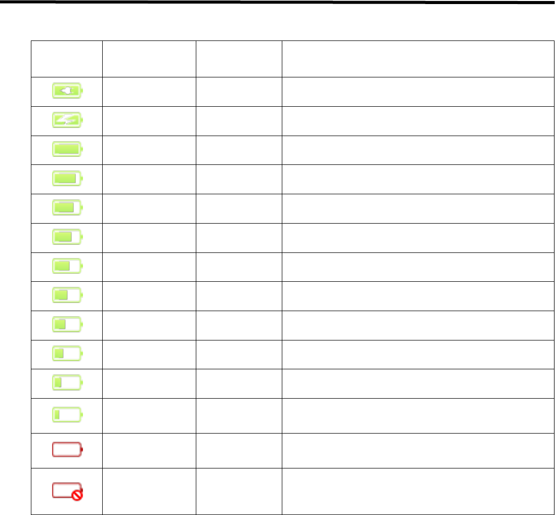
Table 5.3. Battery Remains Indicator
Display
Status
Ext. Pwr
Required Actions
Charge
complement
Ext. cable
& battery
Ext. cable
charging
Ext. cable
& battery
100%
Only battery
90 to 99%
Only battery
80 to 89%
Only battery
70 to 79%
Only battery
60 to 69%
Only battery
50 to 59%
Only battery
40 to 49%
Only battery
30 to 39%
Only battery
20 to 29%
Only battery
10 to 19%
Only battery
Warning message is popped up at the bottom-right.
Recommend to change the battery.
0 to 9%
Only battery
Warning message is popped up at the bottom-right.
Change the battery before the battery is discharged.
No Battery or
Error
Unkown
Change the battery.
If the problem cannot be resolved, ask for consultation to
your sales representative or local DRTECH dealer.
EVS 2430W User’s Manual 5. Operation Procedure
DRT-MAN-091 51
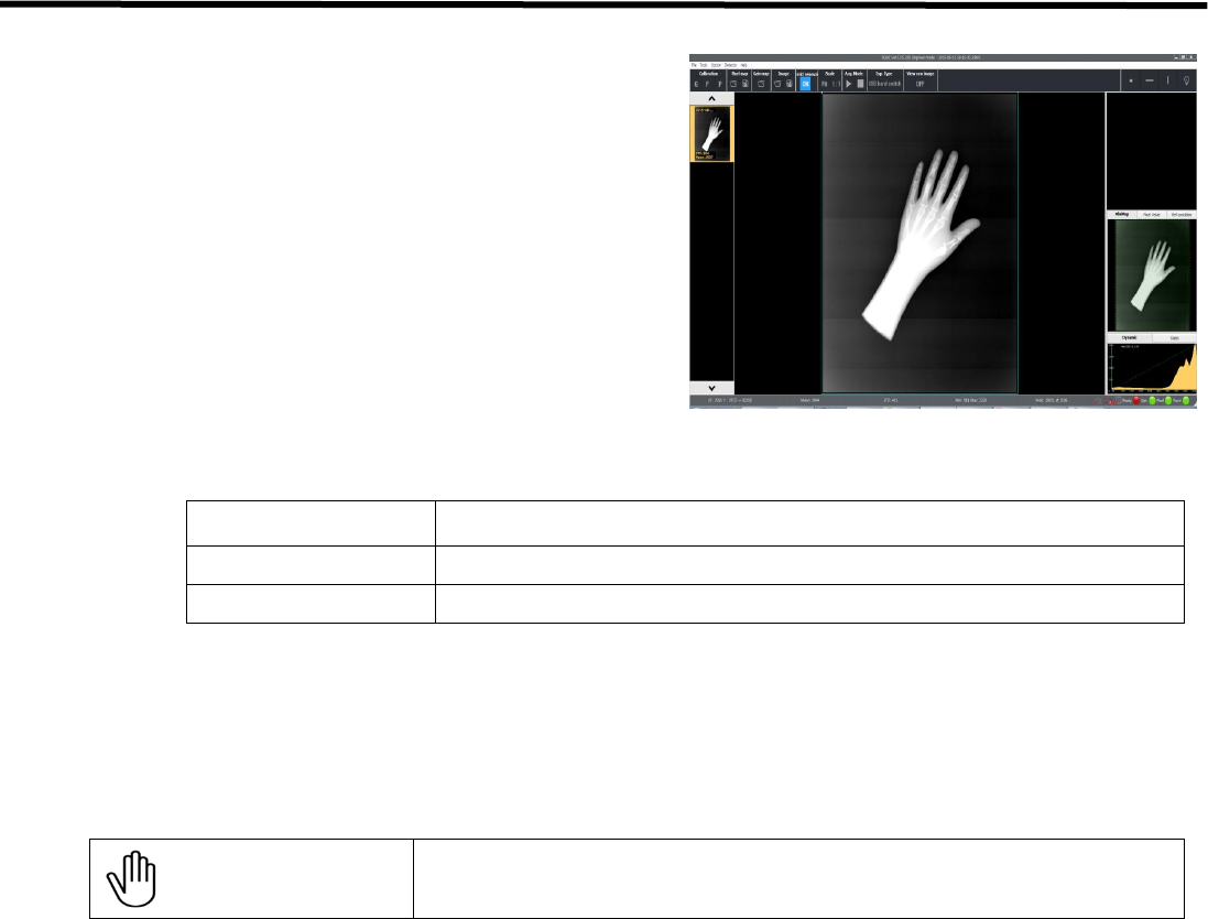
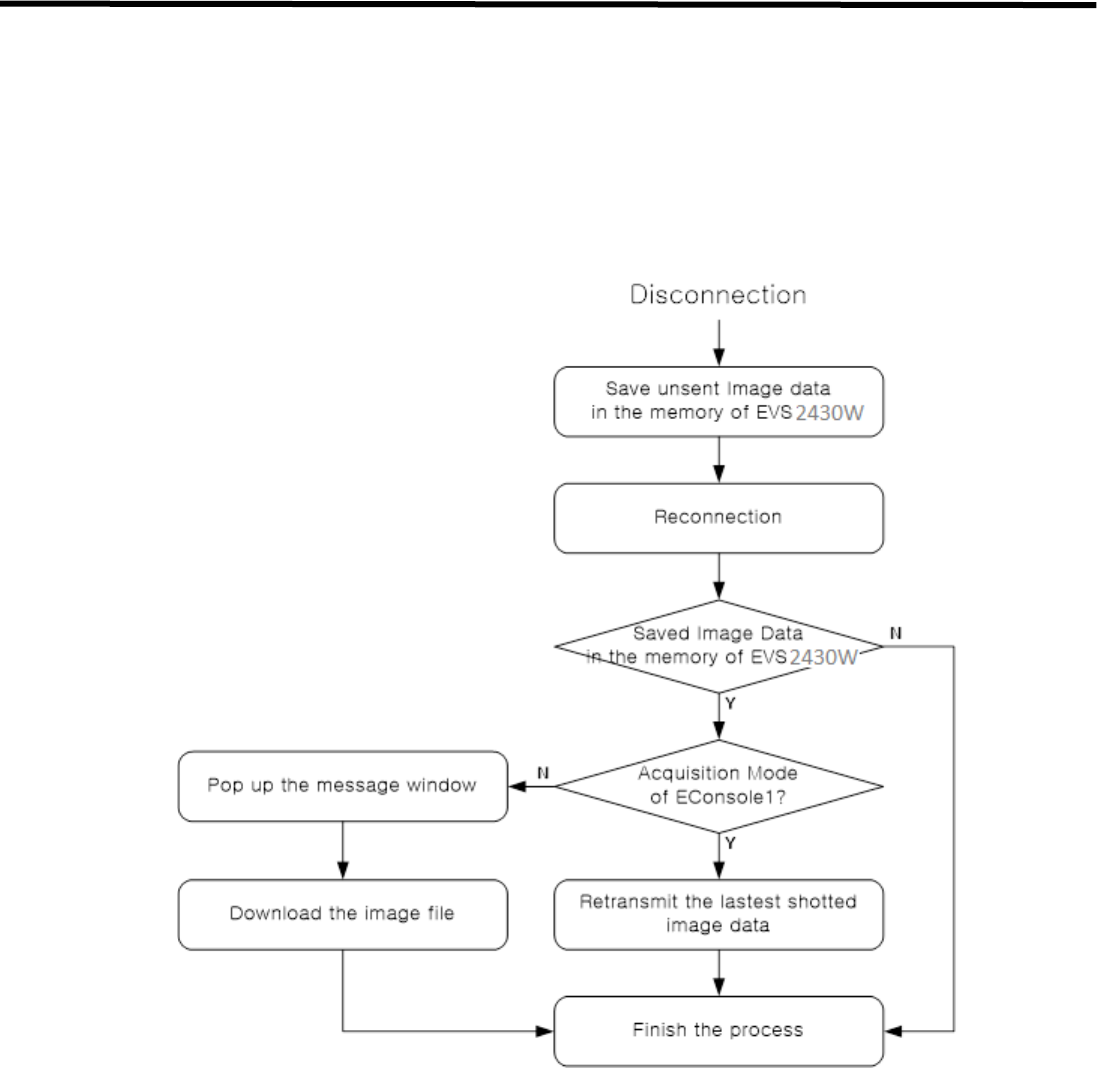
5.2.3. Image Data Retransmission
EVS 2430W can save the image data as file when detector is disconnected from AP during image data transmission.
User can download the image file or receive the lastest shotted image data by using acquisition mode of EConsole1
after reconnection.
Figure 5.2. Flow Chart
If user does not use acquisition mode after reconnection, image data is saved as file. Image file cannot be
retransmitted automatically even if acquisition mode is activated.
For details about operation, refer to the Operation Manual for the EConsole1.

EVS 2430W User’s Manual 5. Operation Procedure
DRT-MAN-091 52
5.3. Ending Use of the Detector
• Turn off the detector
Press the POWER button.
All the LED lamps should be off.
Table5.4. Detector Status List
Lamp type
Power
Lamp
Ready
Lamp
Link
Lamp
AP
Lamp
Color
■ Blue
■ Green
■ Orange
■ Green
■ Green
Power ON
○
X
X
X
X
During detector registration
○
X
X
X
X
Detector registration completed (1 Sec.)
○
X
X
○
★
Communication established
○
X
X
○
★
During exposure preparation
○
X
X
○
★
Ready status or performing an
examination (Ready)
○
☆/○
X
○
★
During image data transmission
○
○
X
○
★
Sleep Mode
○
X
☆
○
★
Deep Sleep Mode
○
X
☆
○
★
Power OFF
X
X
X
X
X
О : Light on
☆ : Blinking (On/Off status changes every second)
Х : Lights off
★ : Blinking slowly (On/Off status changes every 2 seconds)
- : Unspecified status
5.4. Detector Initialization
• Press the AP button for 20 to 25 seconds until AP LED lamp is blinking
• Detector will be connected again
• Setting the parameters of detector such as SSID, IP, etc.
Refer to "7.2.1. Detector Configuration".

EVS 2430W User’s Manual 6. Extension Facility
DRT-MAN-091 53
6. Extension Facility
6.1. X-ray Generator Interface
6.1.1. X-ray Exposure Mode
Table 6.1. Exposure Mode
Mode
Description
Auto Trigger Mode (AT)
1. The detector detects actual amount of X-rays without any connection to the X-ray
generator, and then performs image acquiring to the extent of image acquisition time
and transmits the image data.
2. No signal used (No need of connector interface cable)
• You can use AT mode without connecting the generator with USB SW Box or SSU
physically.
Sync. Trigger Mode
1. The detector receives EXP_REQ signal that X-ray generator is prepared to generate
X-rays.
2. The detector prepares image acquiring and then responds EXP_OK signal to the X-
ray generator.
3. The X-ray generator confirms EXP_OK signal and generates X-ray, then the detector
performs image acquiring, according to image acquisition time and transmits the
image data.
• EXP_REQ (Generator→ Detector), EXP_OK (Detector →Generator)
USB SW Mode
1. EXP_IN signal generates by USB SW Box then the detector receives Ready signal.
And simultaneously, X-ray generator have ready status in
2. The detector prepares image acquiring
3. EXP_IN signal generates by USB SW Box and generates X-ray, then the detector
performs image acquiring, according to image acquisition time and transmits the
image data.
• Ready_IN (USB SW Box -> PC -> Detector and X-ray Generator)
• EXP_IN (USB SW Box -> PC -> Detector and X-ray Generator)
EVS 2430W User’s Manual 6. Extension Facility
DRT-MAN-091 54
6.1.2. Auto Trigger(AT) Mode
AT Mode is available for acquiring images without any connection to X-ray generator. Generator interface cable is not
required
Figure 6.1. AT Mode Configuration
CAUTION
- Make sure to follow operating environment requirements (Temp.:10 to 35 oC)
- If you use AT Mode out of operating environmental requirements, unwanted image can be
acquired without x-ray image acquiring process.
- Do not hit or drop the equipment. Unwanted images can be acquired in the AT Mode if it
receives a strong jolt.
- If you image a thick object in the AT Mode with low X-ray tube voltage, an image may not be
acquired.
- AT performance is proportional to KV energy. Therefore, it is recommended to increase KV
as much as possible and relatively decrease mA and ms.
- When you set x-ray exposure area towards the direction of the detector, the center block of
the detector should be included in the X-ray exposure area. Otherwise, you may not acquire
an image.
- The minimum X-ray exposure area should be wider than 4cm X 8cm on the center block of
detector.
EVS 2430W User’s Manual 6. Extension Facility
DRT-MAN-091 55
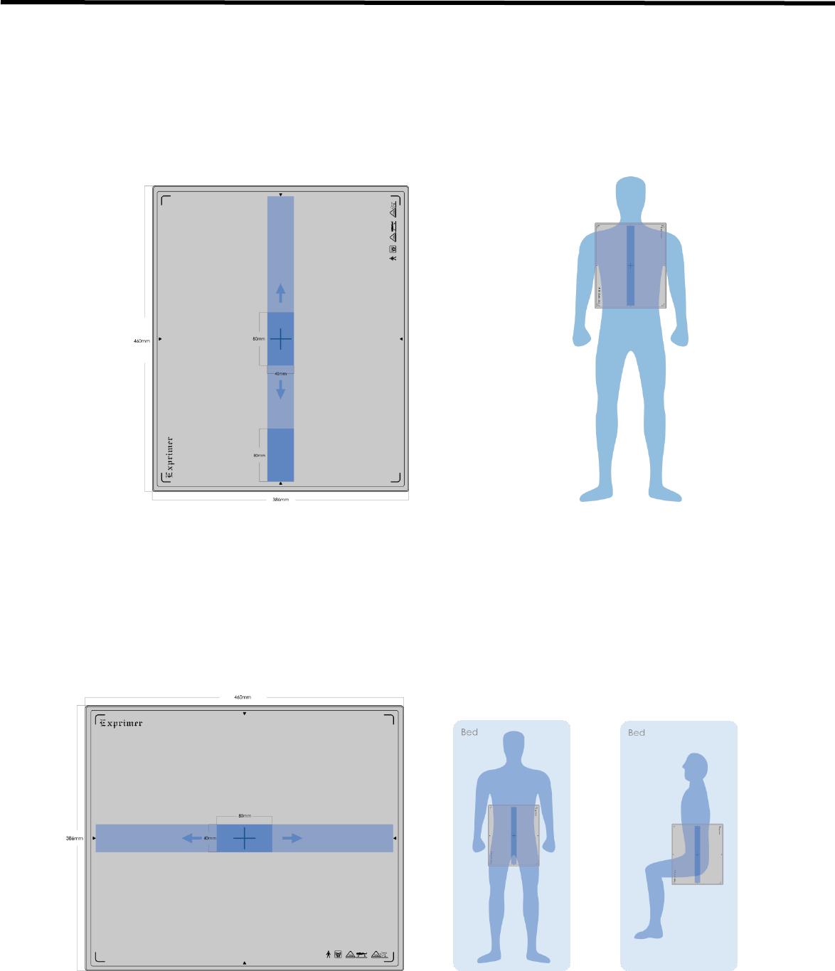
6.1.2.1. Recommendation of setting AT Sensing Area
6.1.2.1.1. Stand Environment
We suggest the collimated area on detector is wider than 4cm X 8cm, and keep along the vertical direction as shown
in figure 6.2.
Figure 6.2 Stand Environment with AT Mode
6.1.2.1.2. Table Environment
We suggest the collimated area on detector is wider than 4cm X 8cm, and keep along the horizontal direction as
shown in figure 6.3
Figure 6.3. Stand Environment with AT Mode
EVS 2430W User’s Manual 6. Extension Facility
DRT-MAN-091 56
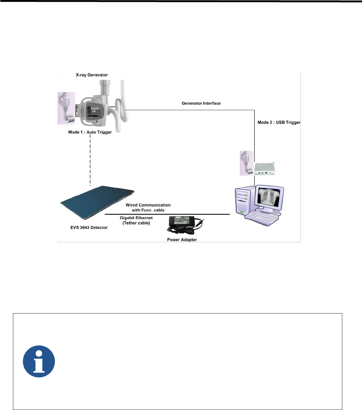
6.1.3. USB SW Mode
USB SW Mode is the most common and recommended exposure mode at a retrofit scope. User can achieve high
quality images with USB SW Mode.
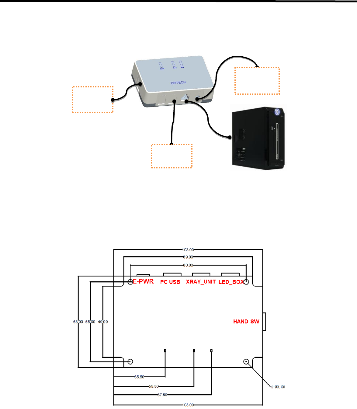
Figure 6.12. EVS 2430W USB Sw Mode Configuration
- The USB interface mode is a wired connection of wireless detector with SSU.
- PC and detector are connected by tether interface cable.
(consistent power supplying by adoptor).
- It is used in case when faster image transmission is needed, compared to a wireless connection.
- A wireless module in the detector is deactivated. (The equipped battery is not consumed)
- Connect the generator with USB SW Box physically to make an exposure in USB SW mode.
- You can use AT mode without connecting the generator with USB SW Box physically.
- Multiple detectors can be configured with one USB Box.
EVS 2430W User’s Manual 6. Extension Facility
DRT-MAN-091 57
6.1.3.1. Wiring USB SW Mode
Figure 6.13. Wiring USB Switch box
6.1.3.2. Connector Description
Figure 6.14. USB Switch box Connector
USB S/W Box
Hand
Switch
X-Ray
Consol
e
Adapter
(Optional)
1m
3m

EVS 2430W User’s Manual 6. Extension Facility
DRT-MAN-091 58
6.1.3.3. Connector Pin Assignment
Num.
Connector Name
Remark
1
PC USB
RJ45-8Pin
2
XRAY_UNIT
RJ11-4Pin
3
LED_BOX
RJ11-6Pin
4
HAND SWITCH
RJ11-4Pin
5
E-PWR
(Adapter CON) DC5V/2A
6.1.3.4. X-ray_UNIT
Pin Num.
Pin Name
Remark
1
XRAY_RDY_COM
* Dip SW Option
2
XRAY_EXP_GEN
3
XRAY_RDY_GEN
4
XRAY_EXP_COM
* Dip SW Option
* XRAY_RDY_COM and XRAY_EXP_COM can be connected using dip switch.
It depends on x-ray generator.
6.1.3.5. Hand Switch
Pin Num.
Pin Name
Remark
1
HAND_SW_RDY_COM
GND
2
HAND_SW_RDY
3
HAND_SW_EXP
4
HAND_SW_EXP_COM
GND
6.1.3.6. PC USB
Pin Num.
Pin Name
Remark
1
VCC (+5V)
-
2
RDY_IN
-
3
LED_SW_CONTROL
-
4
EXP_IN
-
5
EXP_OUT
-
6
GND
-
7
-
Not Connected
8
-
Not Connected

EVS 2430W User’s Manual 6. Extension Facility
DRT-MAN-091 59
6.2. Software Installation
This section gives information about how to install the software on the workstation (PC) and how to configure the
environment for software operation and communication.
6.2.1. Software Classification
DRTECH provides clients who purchase our detector system with software as shown below. User can choose and use
one of the software below.
Software
Description
Econsole1
Image acquisition and adjustment software developed by DRTECH.
There is no need to develop separate software.
Ecali1
A configuration and management software for the detector
Document
Econsole1 Operation Manual
EVS SDK
Software development kit for EVS 2430W detector only, provided by DRTECH
You can develop your own software dedicated to EVS 2430W by using this kit.
Document
EVS 2430W SDK Developer’s Manual
6.2.2. Software Installation
• For a client who uses Econsole1, Install Econsole1 program after reading Econsole1 Operation Manual
carefully.
• For a client who uses EVS SDK, Install the Setup program after reading EVS SDK Developer’s Manual
CAUTION
Be sure to install the software first with perusing the manual,
before configuring Windows environment.
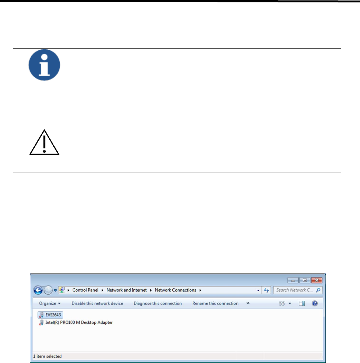
EVS 2430W User’s Manual 6. Extension Facility
DRT-MAN-091 60
6.3. Windows Environment Setting
This section gives information about configuring Windows to communicate with the detector.
The contents in this chapter are made on the basis of Windows 7.
Configuration environment can be different depending on network adaptor manufacturers or
models.
6.3.1. Network Communication
CAUTION
Communication disruption between the detector (Or SSU) and workstation occurs unless the
network adaptor is set properly. It may cause serious repercussion to the product and image
quality.
Network Adaptor Selection
1) Click Start → Control Panel → Network and Internet → Network and Sharing Center → Change
Adapter Setting.
2) Choose the networks adaptor for communicating with the detector and SSU, and then rename it.
3) Click the chosen network adaptor with the right mouse button and click Properties to display the Properties
window.
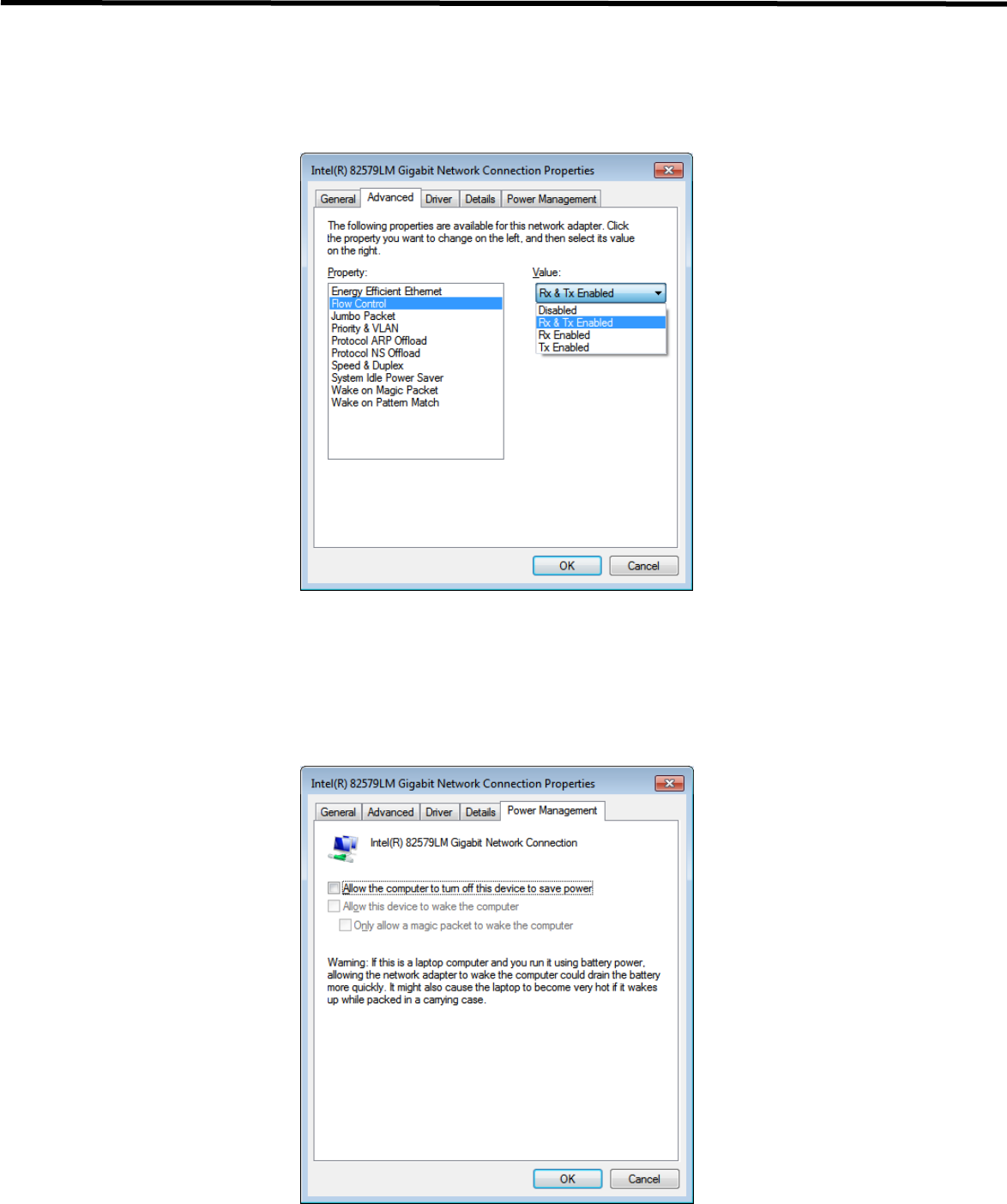
EVS 2430W User’s Manual 6. Extension Facility
DRT-MAN-091 61
Network Adaptor Configuration
1) Click Configure button to open the following dialog box, and then go to the Advanced tab.
2) Choose Flow Control in the list of Properties and click Value button on the right.
3) Power-saving Mode on Network adaptor
- Click the Power Management tab and check on Allow the computer to turn off this device to save
power.
- Click OK button
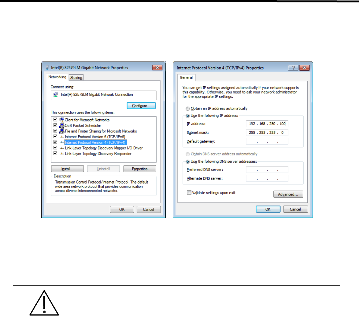
EVS 2430W User’s Manual 6. Extension Facility
DRT-MAN-091 62
4) Protocol selection and IP address setting
- Click Properties button after selecting Internet Protocol Version 4 (TCP/IPv4).
- Input the IP address and subnet mask as shown below, and then click OK button.
CAUTION
- It is recommended to set IP address and Subnet mask in the presented range of this
document.
- If you use IP address and Subnet mask out of the presented range, it would be difficult to
identify the cause or resolve in case of communication disorder.
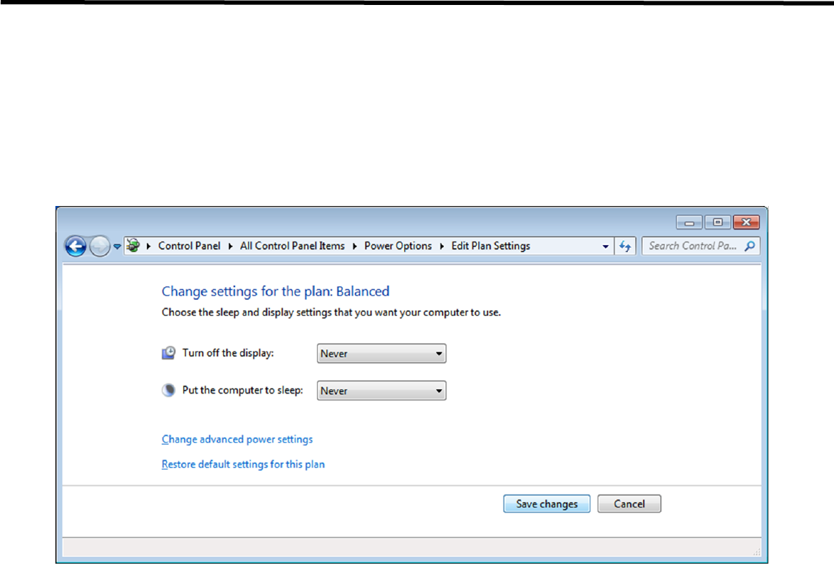
EVS 2430W User’s Manual 6. Extension Facility
DRT-MAN-091 63
6.3.2. Disabling Sleep Mode on Monitor
1) Click Start → Control Panel → Power Options and then move to the Choose when to turn off the display
tab.
2) Set Put the computer to sleep to Never to disable the sleep mode.
3) Click Save changes button.
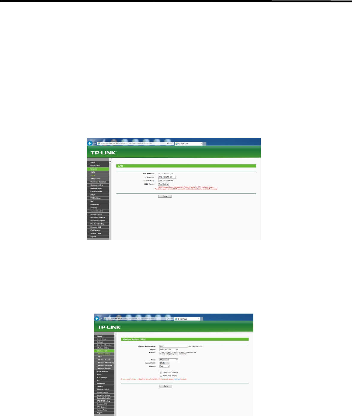
EVS 2430W User’s Manual 7. Device Setting
DRT-MAN-091 64
7. Device Setting
7.1. AP Setting
7.1.1. AP Configuration
Normally, AP setting does not need to be changed by user, because AP is set to match the use environment when the
product is inspected for shipping.
1) Check IP address of AP
- Enter the IP address of AP, as set in ECali1 (192.168.250.98).
- Choose Network tab → LAN. IP address can be seen as stored.
2) Setting wireless communication
- Choose Wireless 5GHz or 2.4GHz → Wireless Setting.
- Register wireless Network Name same with the detector, and select Region, Channel Width, Channel
depending on the use enviroment.
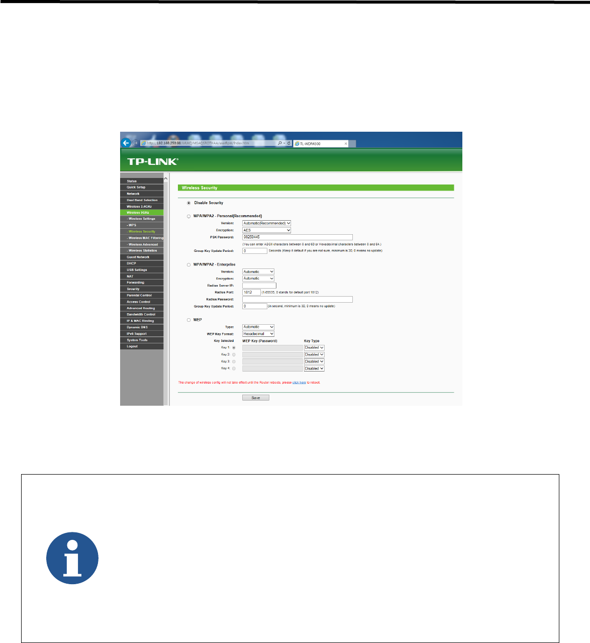
EVS 2430W User’s Manual 7. Device Setting
DRT-MAN-091 65
3) Setting wireless communication
- Choose Wireless 5GHz or 2.4GHz → Wireless Security
- Choose Disable Security and click the Save button
- Detector can not be connected to AP if security is enabled.
- Default IP Address of Detector is 192.168.250.135.
- 13 numbers of channel can be used in 2.4GHz Frequency.
- 8 numbers of channel can be used in 5GHz Frequency.
- Available channel will be limited according to country and region.
- Channel Bonding is for enhancing transmission speed. However, transmission speed may be
decreased due to channel’s interference, even if channel bonding has been done.
- Channel’s (+/-) will be activated in case of using 40MHz Frequency bandwidth.
- The configuration whether bonding with above channel or below channel can be done.
- AP's SSID should be same as Detector’s SSID, if user intends to use wireless communication.

EVS 2430W User’s Manual 7. Device Setting
DRT-MAN-091 66
7.2. Detecting Setting
7.2.1. Detector Configuration
For details about each parameter, refer to the Operation Manual for ECali1
Start up ECali1. Click Option → Configuration → Detector Tab.
Menu
Description
Path to save map files
Register each map file that corresponds to the product
Pre-processing
Value for pre-processing.
Do not change it by yourself.
Serial number
Register the serial number of product.
Router IP
IP address of AP.
The detector can not be connected to AP if router IP is changed.
Grid selection
Select type of the grid and register the path of grid filter.
Exposure mode
Choose exposure mode
Wired/Wireless
Choose communication mode
Image mode
Select image mode
Power management
Waiting time for sleep mode can be adjusted by setting parameters below.
1) Acquisition sleep time
Mode is changed from acquisition mode to sleep mode, after the set waiting time.
2) Deep sleep time
Mode is changed from sleep mode to deep sleep mode, after the set waiting time.
Hardware setting
AP button on detector is activated if Enable AP Button is checked.

EVS 2430W User’s Manual 7. Device Setting
DRT-MAN-091 67
Image TimeOut
Set the time limit to prevent re-transmission request.
Item
Description
Time
The set waiting time for image to be transmitted.
After starting image transmission, the detector ignores received information of image transmission request, if the
following conditions are all met.
- Image is being transmitted :
No interference is allowed during transmission.
- Transmission process is not completed :
After transmission, there is a slight waiting time for the transmission process to be finished.
Deep Sleep Mode
Normal
Detector can be operated and take an exposure at any time.
Sleep
Detector can be operated and take an exposure at any time within 2 seconds.
Deep Sleep
Detector can not be operated. User can take an exposure only if Deep Sleep Mode is canceled.
Power Off
Detector has been turned off. User can take an exposure after detector is rebooted.
- You can prevent unnecessary battery consumption by using the Deep Sleep function.
- When SSU power is supplied to the detector by connecting a tether interface cable, the Deep Sleep function
cannot be operated.
- When using the Deep Sleep function, be sure to check if the detector is in Deep Sleep mode before making an
exposure. You cannot acquire images when the detector is in Deep Sleep mode.
- When the Deep Sleep mode is disabled, the detector needs maximum of 10seconds to wake up. It may not be
available to acquire images during this time.

EVS 2430W User’s Manual 7. Device Setting
DRT-MAN-091 68
7.2.2. Detector Power Save Management
Meaning
Normal
Detector can be operated and take an exposure at any time.
Sleep
Detector can be operated and take an exposure at any time within 2 seconds.
Deep Sleep
Detector can not be operated. User can take an exposure only if Deep Sleep Mode is canceled.
Power Off
Detector has been turned off. User can take an exposure after detector is rebooted.
Entry Condition for Power Save Mode
Mode
Description
Normal
-
Sleep
Activates when the detector has not been used for a certain time.
Deep Sleep
Time can be set to automatically go into Deep Sleep mode, after a certain period of time passed
under sleep mode.
Power Off
Detector is turned off if detector has not been used for a set period of time (Power off) from the
entry time of Deep Sleep Mode. However, in case of not using Deep Sleep mode function,
Detector is turned off if detector has not been used for certain time (Power Off After).
Disabling Power Save Function
Mode
Description
Normal
-
Sleep
Detector is in sleep mode.
Deep Sleep
Turn off Sleep Mode After setting time.
Call the function for turning off Deep Sleep Mode at SDK.
Power Off
Reboot the detector with pressing power button on the detector.

EVS 2430W User’s Manual 7. Device Setting
DRT-MAN-091 69
Other Information
Mode
Initial Value
Turnaround Time
Normal
-
Sleep
-
Approx. 2 sec.
Deep Sleep
OFF /10 min
Approx. 10 sec.
Power Off
OFF /60 min
Approx. 40 sec.
CAUTION
- When using the Sleep function, be sure to check if the detector is in Sleep mode before
making an exposure. You cannot acquire images when the detector is in Sleep mode.
- When the Sleep mode is disabled, the detector needs max. 1 to 2 seconds to wake up. It
may not be available to acquire images during this time.

EVS 2430W User’s Manual 8. Troubleshooting
DRT-MAN-091 70
8. Troubleshooting
8.1. Failed to Turn the Detector On
Symptom
- Failed to turn on the power of the detector.
Possible Causes
- Not installing battery pack well
- Dead battery pack
- Battery pack or Detector is broken
Solutions
1) Install the battery pack.
2) Charge the battery pack.
3) Check the result after getting rid of the battery pack and connecting the tether interface cable.
4) Replace other battery packs and check the results.
5) Replace other Detectors and check the results.
6) Replace corresponding devices.
8.2. Errors in Detector LED
Symptom
- Ready LED (Orange) lamps of detector are blinking 3 times/sec.
Possible Cause
- Internal hardware errors of the detector
Solutions
1) Consult with service engineers of DRTECH

EVS 2430W User’s Manual 8. Troubleshooting
DRT-MAN-091 71
8.3. The LINK LED does Not Turn on
Symptom
- The LINK LED does not turn on when power LED is ON
Possible Cause
- Detector registeration error
Solutions
1) Check if AP is turned on.
2) Check if network cable is plugged to ethernet port of AP.
3) Check the network cable connection between workstation and AP.
4) Check the windows and network environment again such as firewall and IP address setting.
5) Check if the SSID of Detector is same as SSID of AP by using tether interface cable.
8.4. Rapid Consumption of Battery
Symptom
- Consumption of a fully charged battery pack is fast.
Possible Causes
- Performance decrease caused by usage of long time.
- Usage of battery pack in low temperature environment
Solutions
1) Replace to new battery pack if the battery pack has been used for a long time. (Battery pack is a consumable)
2) Use battery pack in normal room temperature environment. Charging capacity of battery pack in low
temperature environment will decrease the capacity.

EVS 2430W User’s Manual 8. Troubleshooting
DRT-MAN-091 72
8.5. Battery Pack or Installation Part of Battery is Getting Hot
Symptom
- Battery pack or compartment for installation of battery pack is getting hot.
Possible Causes
- Battery pack failure
- Detector Failure
Solutions
1) Do not use the battery pack
2) Consult with service engineers of DRTECH
8.6. The Power Switch of SSU or Status LED is not working
Symptom
- The power switch of SSU is not working.
- The status LED of SSU is not responding.
Possible Causes
- Power cable is broken down.
- Errors in the fuse
- Internal circuit is broken down.
Solutions
1) Check the connection between AC power cable and SSU.
2) Replace the fuse.

EVS 2430W User’s Manual 9. Maintenance and Inspection
DRT-MAN-091 73
9. Maintenance and Inspection
In order to ensure that the equipment is used safely and normally, be sure to inspect the equipment before use. If any
problem is found during the inspection and cannot be corrected, please contact your sales representative or local
DRTECH dealer.
Daily Inspection
WARNING
For safety reasons, be sure to turn OFF the power to each piece of
equipment before the following procedures. Otherwise, an electric shock
may result.
Cable
1) Ensure that cables are not damaged and cable jackets are not torn.
2) Ensure that the power cord plugs are securely connected to both the equipment AC inlet and the AC outlet.
Detector
1) Ensure that there are no loose screws or broken parts.
2) Ensure that there is no dust or foreign substance on the external connector.
3) Ensure that there are no broken parts or short-circuits in the power supply conector.
After turning on the power
Be sure to start ECali1 before performing the following inspection.
1) Perform test exposure.
Monthly Inspection
1) Ensure that there are no loose screws or broken parts.
2) Ensure that there is no dust or foreign substance on the external connector.
Yearly Inspection
1) Perform a Performance Test or Self-diagnosis using a phantom or resolution chart, etc.
Irregular Inspection
Calibration
1) Perform Calibration when exposure conditions have changed significantly.
For details, refer to the Setup Guide for ECali1.

EVS 2430W User’s Manual 10. Specification
DRT-MAN-091 74
10. Specification
10.1. Main Specifications
10.1.1. EVS 2430W / EVS 2430GW X-ray Detector
[Dimensional Diagram] (Unit mm)
Figure 10.1 Detector Dimension
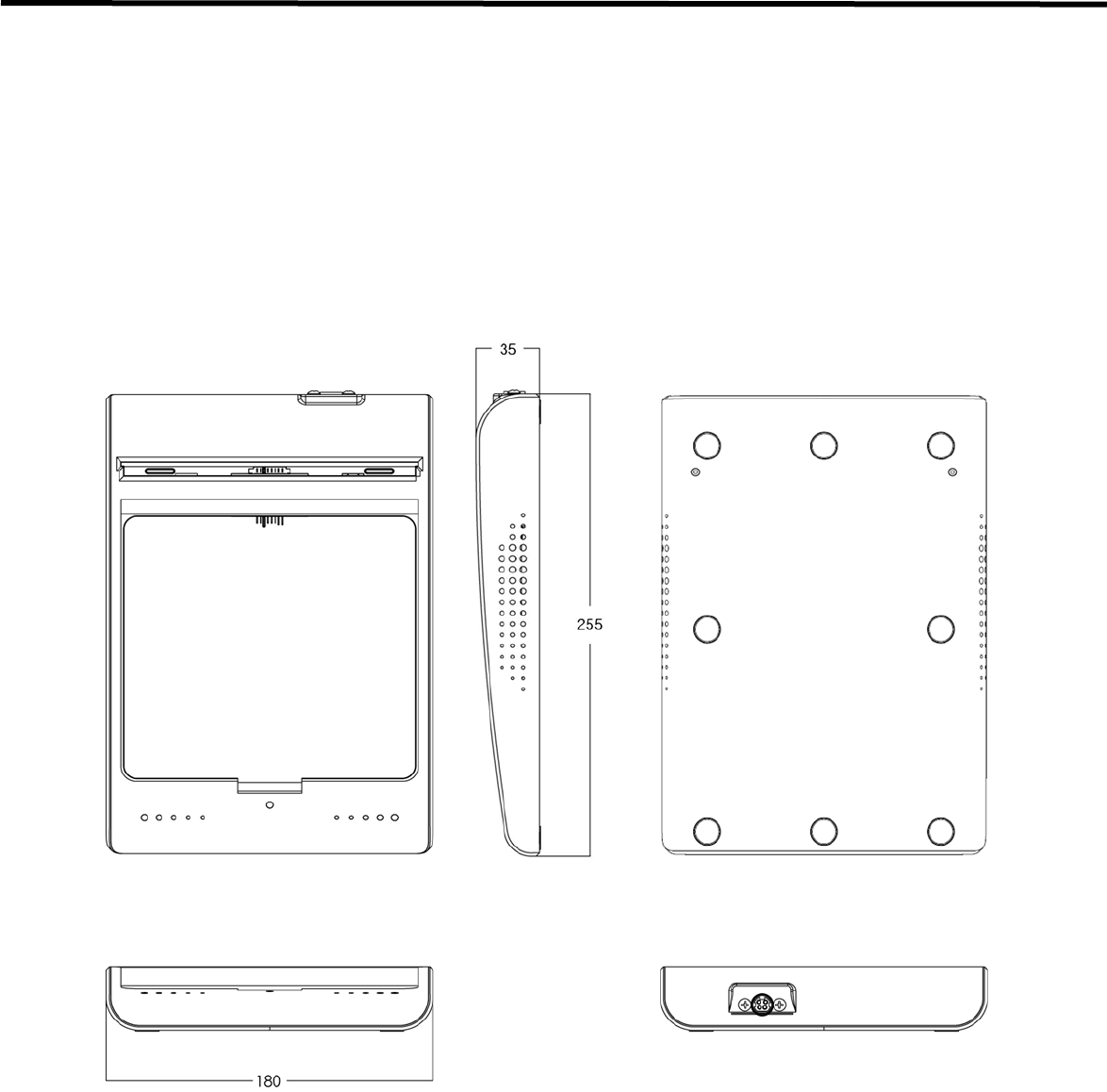
EVS 2430W User’s Manual 10. Specification
DRT-MAN-091 75
10.1.2. Battery Charger System
[Dimensional Diagram] (Unit mm)
Figure 10.2 Battery Charger System Demension
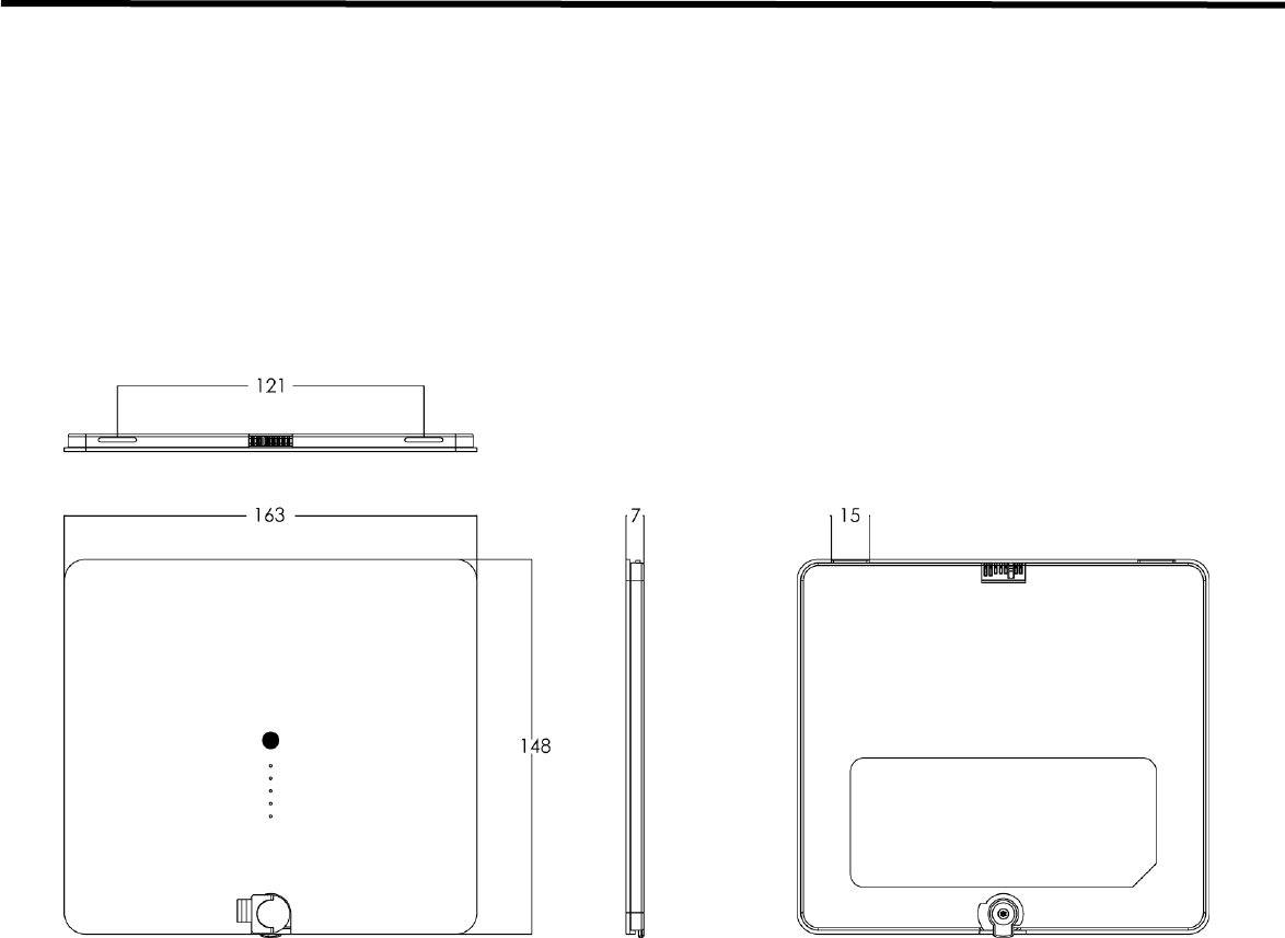
EVS 2430W User’s Manual 10. Specification
DRT-MAN-091 76
10.1.3. Battery Pack
[Dimensional Diagram] (Unit mm)
Figure 10.3 Battery Pack Demension
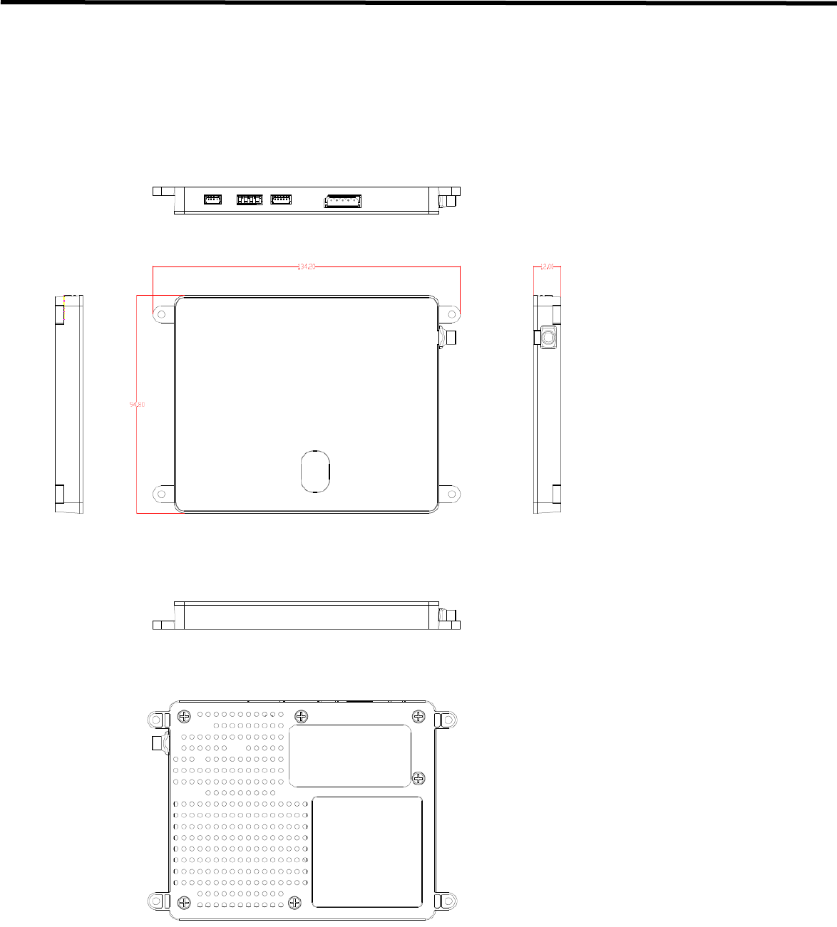
EVS 2430W User’s Manual 10. Specification
DRT-MAN-091 77
10.1.4. EVS-WPCS
[Dimensional Diagram] (Unit mm)
Figure 10.4 EVS-WPCS Demension

EVS 2430W User’s Manual 10. Specification
DRT-MAN-091 78
10.2. Charateristics
Typical Patient Doses
- Typical patient doses are equivalent to 500-1000 speed film/screen systems.
Sensitometric Characteristics and Dynamic Range
- EVS 2430W Wireless responds linearly against the exposure range for 500-1000 speed film/screen where
it can depict the clinical information. It means that EVS 2430W fully covers a dynamic range of 0.2-20 μGy
at least.
Spatial Resolution Properties
- EVS 2430W
A typical MTF value at 2 lp/mm, than 40%.
- EVS 2430GW
A typical MTF value at 2 lp/mm, than 25%.
DQE
- EVS 2430W
A typical DQE value at 1 lp/mm is 55%.
- EVS 2430GW
A typical DQE value at 1 lp/mm, than 50%.
The product safety standards that apply to the EVS 2430W, which includes the following equipments, are as
below.
• Detector
• Battery Charger
• Battery Pack
• WPCS Module
• Wiring unit (sold separately, optional unit)

EVS 2430W User’s Manual 10. Specification
DRT-MAN-091 79
10.3. Packing
Note
Figures and Illustrations in this Technical Manual are provided for reference only and may differ from the actual
product appearance.
10.3.1. Product Configuration List
Table 10.1. EVS 2430W (Wireless) Supply Part List
No.
Product Name
Q'ty
Remarks
1
TFT Detector Plate
1
2
Battery Charger
1
3
Battery Pack
2
4
Power Adaptor
1
5
AC Power Cable
1
6
Tether Cable
7
Functional Cable
8
LAN Cable
1
9
LAN Card
1
10
Access Point
1
11
Software CD
1
Table 10.2. Optional Product List
No.
Product Name
Q'ty
Remarks
1
System Synchronization Unit (SSU)
2
AC Power Cable
3
Generator Interface Cable set
4
Adaptor Cable
5
USB Switch Box Set
6
Protection Case
7
Grid for Protection Case
8
Surface Pro 3
9
DROC S/W
10
Workstation
Note
If you find any items missing from the list above upon unpacking, please contact your dealer.
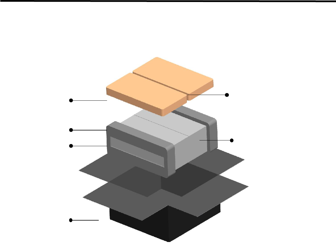
EVS 2430W User’s Manual 10. Specification
DRT-MAN-091 80
10.3.2. Assemble Package
Warning
Operational issues may occur if inappropriate force is applied to the product during unboxing. Please handle the box
containing the product with care.
Note
The packaging that came with the product should not be damaged or discarded as it is needed for after-sales service
or for exchanging the product with a new product. If the packaging or any component is missing, the damaged product
cannot be refunded or exchanged with a new product.
Accessory Box package
Cushion
Detector Panel Package
EVS 2430W Package
Accessory Box Package
Cushion
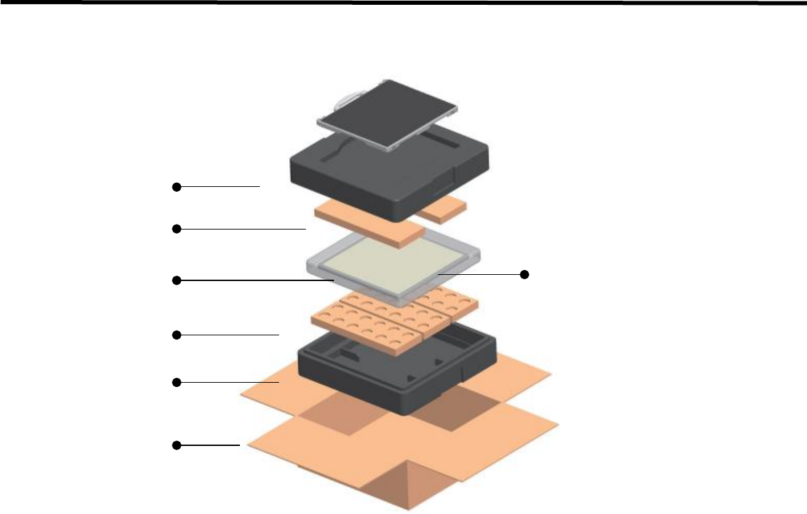
EVS 2430W User’s Manual 10. Specification
DRT-MAN-091 81
10.3.3. Detector Panel Package
Note
• The PCM pack can explode from a hard impact or a contact with a sharp object.
• It is non-toxic and may not cause serious harm. However, please take extra precaution as it is a chemical
substance, and remember to carefully follow the instructions.
• If the inner chemicals get on your body, immediately wash it off thoroughly with clean water.
• If the inner chemicals get in your eyes, wash your eyes with tap water for more than 15 minutes and consult your
doctor.
• If the contents are accidentally ingested, drink two glasses of water (500ml) and consult your doctor.
• How to discard the content: Please discard used PCM packs using one of the following methods.
• Collect a certain number of packs and send them to the manufacturer.
• Treat them in a nearby chemical waste processing facility.
Note
• PCM Pack [Phase Change Material Pack]
• The PCM pack placed in the Bottom cushion is intended to maintain mild temperature over a certain period of time
in order to protect Detector from cold weather.
• The PCM is originally a liquid, and it begins to emit heat when the box is left for a long period at low temperature
below zero Celsius. Its phase changes to a solid state gradually during the heat radiation.
• The PCM is a reusable material, which means the solid state PCM returns to its liquid state within approximately 2
hours of heating over 35 degrees Celsius. Utilizing this method, the PCM can be used repeatedly.
• The liquid PCM should be stored around room temperature, and can be reused in the same way as the original
packing when any transportation is needed.
Top cushion
PCM Pack
600 Detector
PCM Pack
Bottom cushion
Detector panel Package
Inner form

EVS 2430W User’s Manual 10. Specification
DRT-MAN-091 82
10.3.4. Component Box Assemble Package
10.3.4.1. AP Box Component
No
Product Name
Q'ty
Remarks
1
Access Point
1
Default
2
Tether Cable
1
3
Functional Cable
1
4
USB Switch Box
1
Optional
5
USB Cable
1
6
Hand Switch
1
7
X-Ray Cable
1
10.3.4.2. Battery Box Component
No
Product Name
Q'ty
Remarks
1
Battery Pack
2
Default
2
Battery Charger
1
3
Software CD
1
4
Power Adaptor
1
5
Power Code
1
6
LAN Card
1
7
LAN Cable
1
8
Adaptor Cable
1

EVS 2430W User’s Manual 11. Regulatory Information
DRT-MAN-091 83
11. Regulatory Information
11.1. Medical Equipment Safety Standards
Medical Equipment Classification
Type of protection
against electrical shock
Class I ME Equipment
Degree of protection
against electrical shock
Type B Applied Parts (Applied Part: Detector Panel)
Degree of protection
against ingress of water
IPX4
Mode of operation
Continuous Operation
Flammable anesthetics
Not suitable for use in the presence of a flammable anesthetic mixture with air or
with oxygen or nitrous oxide
Product Safety Standards
1) USA and Canada
ANSI/AAMI ES60601-
1:2005/(R)2012 and
A1:2012,, C1:2009/(R)2012
and A2:2010/(R)2012
Medical Electrical Equipment - Part 1 (IEC 60601-1:2005, Mod)
CAN/CSA-C22.2 No. 60601-
1:14 -
Medical electrical equipment - Part 1 (Adopted IEC 60601-1:2005, third edition,
2005-12, incl. Am1:2012, with Canadian deviations), Third Edition
IEC 60601-1-1 Ed.2.0:2000
Medical electrical equipment – Part 1-1 : Collateral standard: Safety requirements
for medical electrical systems
IEC 60601-1-2 Ed.2.1:2004
Medical electrical equipment – Part 1-2 : Collateral standard: Electromagnetic
compatibility-Requirements and tests
IEC 60601-1-3 Ed.1.0:1994
Medical electrical equipment – Part1 : Collateral standard: General requirements
for radiation protection in diagnostic X-ray equipment
IEC 60601-1-4 Ed.1.1:2000
Medical electrical equipment – Part 1-4 : Collateral Standard: Programmable
electrical medical systems
IEC 60601-2-32 Ed.1.0:1994
Medical electrical equipment – Part 2 : Particular requirements for the safety of
associated equipment of X-ray equipment
ISO 10993-1:2003/-5:1999/
10993-10:2002+A1:2006
Biological evaluation of medical devices
Part 1 : Evaluation and testing within a risk management process
Part 5 : Tests for in vitro cytotoxicity
Part 10 : Tests for irritation and delayed-type hypersensitivity

EVS 2430W User’s Manual 11. Regulatory Information
DRT-MAN-091 84
2) European Union
MDD(93/42/EEC)
Medical Device Directive
EN ISO 13485:2003+AC:2007
Medical devices – Quality management systems – Requirements for regulatory
purposes
EN 60601-1:1990+
A1:1993+A2:1995+A13:1996
Medical electrical equipment – Part1 : General requirements for Safety
EN 60601-1-1:2001
Medical electrical equipment – Part 1-1 : Collateral standard : Safety
requirements for medical electrical systems
EN 60601-1-2:2001
Medical electrical equipment – Part 1-2 : Collateral standard : Electromagnetic
compatibility-Requirements and tests
EN 60601-1-3(29.203):1994
Medical electrical equipment – Part 1-3 : Collateral standard : General
requirements for radiation protection in diagnostic X-ray equipment
EN 60601-1-4:1996+A1:1999
Medical electrical equipment – Part 1-4 : Collateral Standard : Programmable
electrical medical systems
EN 60601-1-6:2004
Medical electrical equipment – Part 1-6 : Collateral Standard : Usability
EN 60601-2-32:1994
Medical electrical equipment – Part 2 : Particular requirements for the safety of
associated equipment of X-ray equipment
EN 62304:2006
Medical device software – Software life cycle processes
EN 62366:2008
Medical device – Application of usability engineering to medical devices
EN ISO 14971:2007
Medical device – Application of risk management to medical devices
EN ISO 10993-1:2003/-5:1999/
10993-10:2002+A1:2006
Biological evaluation of medical devices – Part 1 : Evaluation and testing
within a risk management process

EVS 2430W User’s Manual 11. Regulatory Information
DRT-MAN-091 85
11.2. Radio Frequency(RF) Compliance Information
Declaration of Conformity
U.S.A.
FCC Part 15 Subpart B Class A and Part 15 Subpart C (RF Exposure)
Canada
RSS-210
European Union
(and EEA)
ETSI EN300 328-1,-2 (Emission)
ETSI EN301 489-1.-17 (Immunity)
Australia
AS4268
Singapore
IDA TS-14
1) For U.S.A. and Canada
• FCC/IC Compliance
This device complies with Part 15 of the FCC Rules and RSS-Gen of IC Rules.
Operation is subject to the following two conditions :
i. This device may not cause harmful interference.
ii. This device must accept any interference received, including interference that may cause undesired
operations.
• FCC ID
EVS 2430W : RNH-EVS2430W
EVS WPCS : RNH-EVSWPCS
Note :
This equipment has been tested and found to comply with the limits for a Class B digital device, pursuant to part 15 of
the FCC Rules.
These limits are designed to provide reasonable protection against harmful interference in a residential installation.
This equipment generates, uses, and can radiate radio frequency energy and, if not installed and used in accordance
with the instructions, may cause harmful interference to radio communications.
However, there is no guarantee that interference will not occur in a particular Installation.
If this equipment dose cause harmful interference to radio or television reception, which can be determined by turning
the equipment off and on, the user is encourage to try to correct the interference by one or more of the following
measures:
• Reorient or relocate the receiving antenna.
• Increase the separation between the equipment and receiver.
• Connect the equipment into an outlet of a circuit different from that to which the receiver is connected.
• Consult the dealer or an experienced radio/TV technician for assistance.

EVS 2430W User’s Manual 11. Regulatory Information
DRT-MAN-091 86
• FCC WARNING:
Changes or modifications not expressly approved by the party responsible for compliance could void the user’s
authority to operate the equipment.
This transmitter must not be co-located or operated in conjunction with any other antennas or transmitters.
.
• RF Exposure Compliance
The available scientific evidence does not show that any health problems are associated with using low power
wireless devices. There is no proof, however, that these low power wireless devices are absolutely safe. Low
power wireless devices emit low levels radio frequency energy (RF) in the microwave range while being used.
Whereas high levels of RF can produce health effects (by heating tissue), exposure of low-level RF that does
not produce heating effects causes no known adverse health effects. Many studies of low-level RF exposures
have not found any biological effects. Some studies have suggested that some biological effects might occur,
but such findings have not been confirmed by additional research. EVS 2430W Wireless has been tested and
found to comply with FCC/IC radiation exposure limits set forth for an uncontrolled equipment and meets the
FCC radio frequency (RF) Exposure Guidelines in Supplement C to OET65 and RSS-102 of the IC radio
frequency (RF) Exposure rules.
• Disposal
Disposal of this product in an unlawful manner may have negative effects on health and on the environment.
When disposing this product, therefore, be absolutely sure to follow the procedure which is in conformity with
the laws and regulations applicable in your area.
The expected life span of EVS 2430W system is about 3 years.

EVS 2430W User’s Manual 11. Regulatory Information
DRT-MAN-091 87
2) For European Union (and EEA)
English
Hereby, DRTECH Corporation, declares that this EVS 2430W and EVS 2430GW Wireless is in
compliance with the essential requirements and other relevant provisions of Directive 1999/5/EC.
Česky
DRTECH Corporation tímto prohlašuje, že tento EVS 2430W Wireless je ve shodě se základními
požadavky a dalšími příslušnými ustanoveními směrnice 1999/5/ES.
Dansk
Undertegnede DRTECH Corporation erklæ rer herved, at følgende udstyr EVS 2430W Wireless
overholder de væ sentlige krav og øvrige relevante krav i direktiv 1999/5/EF.
Deutsch
Hiermit erklärt DRTECH Corporation, dass sich das Gerät EVS 2430W Wireless in Ü bereinstimmung
mit den grundlegenden Anforderungen und den übrigen einschlägigen Bestimmungen der Richtlinie
1999/5/EG befindet.
Eesti
Käesolevaga kinnitab DRTECH Corporation seadme EVS 2430W Wireless vastavust direktiivi
1999/5/EÜ põhinõuetele ja nimetatud direktiivist tulenevatele teistele asjakohastele sätetele.
Español
Por medio de la presente DRTECH Corporation declara que el EVS 2430W Wireless cumple con los
requisitos esenciales y cualesquiera otras disposiciones aplicables o exigibles de la Directiva
1999/5/CE.
Ελληνική
ΜΕ ΤΗΝ ΠΑΡΥΣΑ DRTECH Corporation ΔΗΛΩΝΕΙ ΤΙ EVS 2430W Wireless ΣΥΜΜΡΦΩΝΕΤΑΙ
ΠΡΣ ΤΙΣ ΥΣΙΩΔΕΙΣ ΑΠΑΙΤΗΣΕΙΣ ΚΑΙ ΤΙΣ ΛΙΠΕΣ ΣΕΤΙΚΕΣ ΔΙΑΤΑΕΙΣ ΤΗΣ ΔΗΓΙΑΣ 1999/5/ΕΚ.
Français
Par la présente DRTECH Corporation déclare que l’appareil EVS 2430W Wireless est conforme aux
exigences essentielles et aux autres dispositions pertinentes de la directive 1999/5/CE.
Italiano
Con la presente DRTECH Corporation dichiara che questo EVS 2430W Wireless è conforme ai
requisiti essenziali ed alle altre disposizioni pertinenti stabilite dalla direttiva 1999/5/CE.
Latviski
Ar šo DRTECH Corporation deklare, ka EVS 2430W Wireless atbilst Direktivas 1999/5/EK
butiskajam prasibam un citiem ar to saistitajiem noteikumiem.
Lietuviu
Šiuo DRTECH Corporation deklaruoja, kad šis EVS 2430W Wireless atitinka esminius reikalavimus
ir kitas 1999/5/EB Direktyvos nuostatas.
Nederlands
Hierbij verklaart DRTECH Corporation dat het toestel EVS 2430W Wireless in overeenstemming is
met de essentiële eisen en de andere relevante bepalingen van richtlijn 1999/5/EG.
Malti
Hawnhekk, DRTECH Corporation, jiddikjara li dan EVS 2430W Wireless jikkonforma malhtigijiet
essenzjali u ma provvedimenti ohrajn relevanti li hemm fid-Dirrettiva 1999/5/EC.
Magyar
Alulírott, DRTECH Corporation nyilatkozom, hogy a EVS 2430W Wireless megfelel a vonatkozó
alapvetõ követelményeknek és az 1999/5/EC irányelv egyéb elõírásainak.
Polski
Niniejszym DRTECH Corporation oswiadcza, ze EVS 2430W Wireless jest zgodny z zasadniczymi
wymogami oraz pozostalymi stosownymi postanowieniami Dyrektywy 1999/5/EC.
Português
DRTECH Corporation declara que este EVS 2430W Wireless está conforme com os requisitos
essenciais e outras disposições da Directiva 1999/5/CE.
Slovensko
DRTECH Corporation izjavlja, da je ta EVS 2430W Wireless v skladu z bistvenimi zahtevami in
ostalimi relevantnimi dolocili direktive 1999/5/ES.
Slovensky
DRTECH Corporation týmto vyhlasuje, že [typ zariadenia] splna základné požiadavky a všetky
príslušné ustanovenia Smernice 1999/5/ES.
Suomi
DRTECH Corporation vakuuttaa täten että EVS 2430W Wireless tyyppinen laite on direktiivin
1999/5/EY oleellisten vaatimusten ja sitä koskevien direktiivin muiden ehtojen mukainen.
Svenska
Härmed intygar DRTECH Corporation att denna EVS 2430W Wireless står I överensstämmelse med
de väsentliga egenskapskrav och övriga relevant bestämmelser som framgår av direktiv 1999/5/EG.
Íslenska
Hér með lýsir DRTECH Corporation yfir því að EVS 2430W Wireless er í samræ mi við grunnkröfur
og aðrar kröfur, sem gerðar eru í tilskipun 1999/5/EC.
Norsk
DRTECH Corporation erklæ rer herved at utstyret EVS-2430W Wireless er i samsvar med de
grunnleggende krav og øvrige relevante krav i direktiv 1999/5/EF.

EVS 2430W User’s Manual 11. Regulatory Information
DRT-MAN-091 88

EVS 2430W User’s Manual 11. Regulatory Information
DRT-MAN-091 89
AT
BE
BG
CY
CZ
DK
EE
FI
FR*
DE
GR
HU
IE
IT
LV
LT
LU
MT
NL
PL
PT
RO
SK
SI
ES
SE
GB
IS
LI
NO
CH
* In France, outdoor use of this equipment is prohibited.
3) For Singapore
Complies with IDA Standards N1624-10
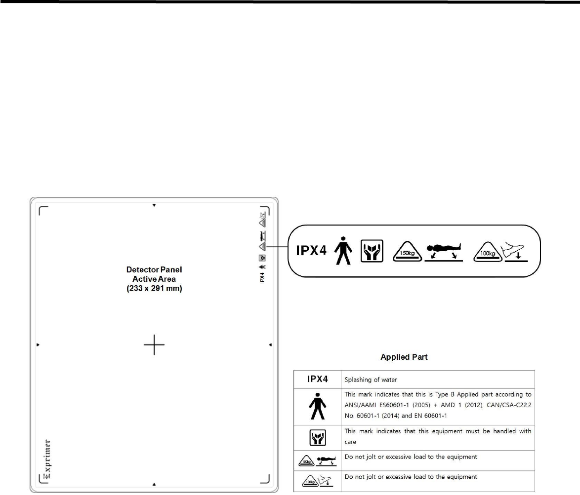
EVS 2430W User’s Manual 11. Regulatory Information
DRT-MAN-091 90
11.3. Labels and Marking on the Equipment
The EVS 2430W detector and other components have labels and markings on them.
Their contents and locations are indicated below.
11.3.1. Detector
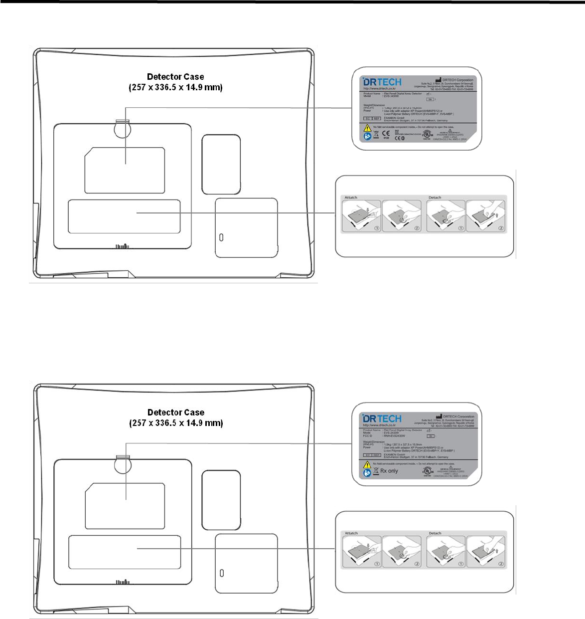
EVS 2430W User’s Manual 11. Regulatory Information
DRT-MAN-091 91
< EVS 2430W >
< EVS 2430W_Use for USA only >
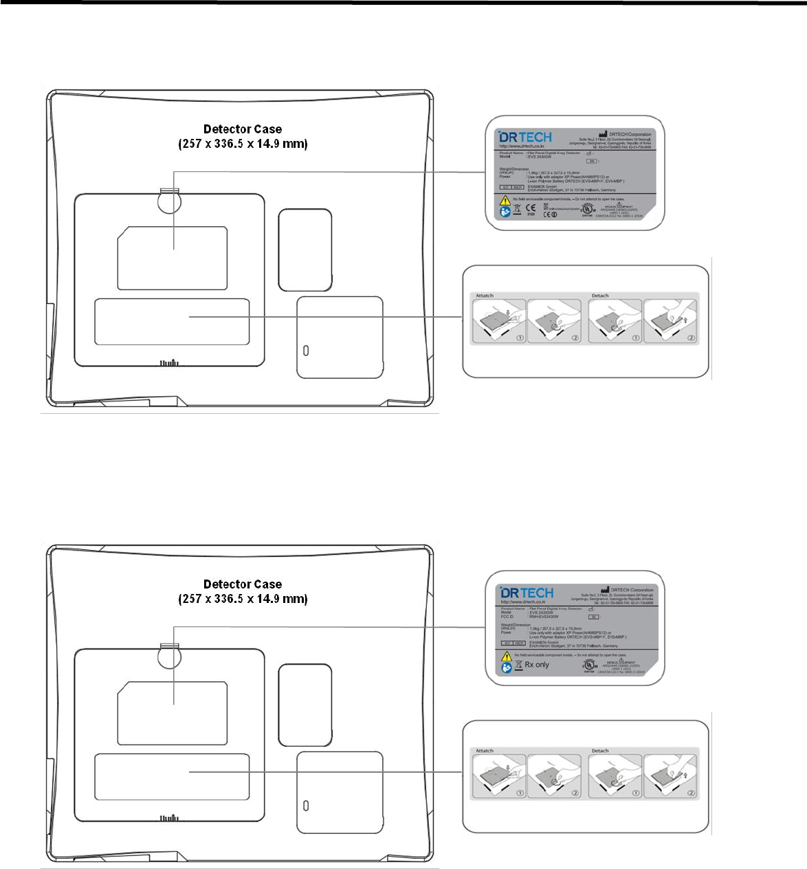
EVS 2430W User’s Manual 11. Regulatory Information
DRT-MAN-091 92
< EVS 2430W Gadox Version >
< EVS 2430W Gadox Version_Use for USA only >
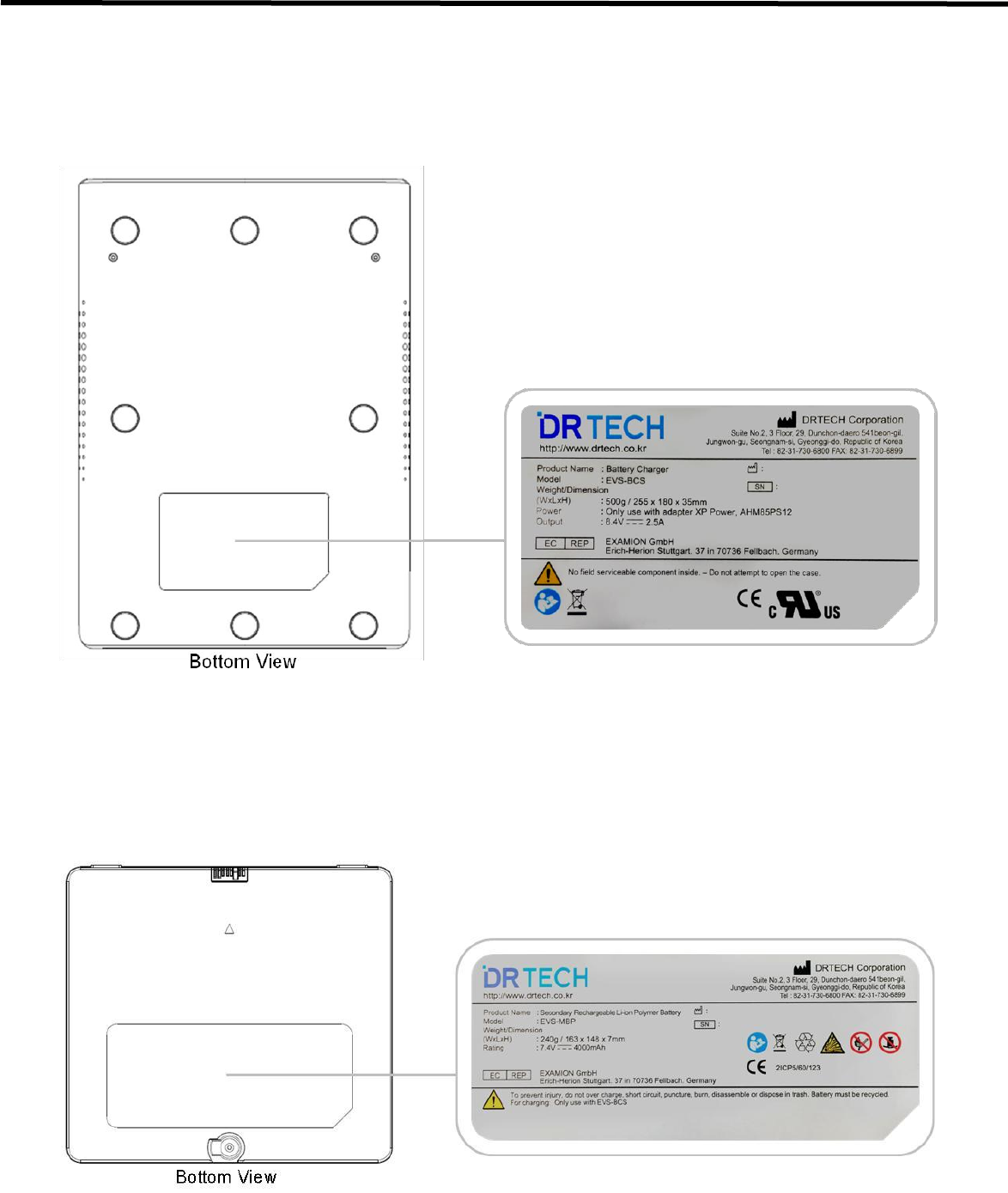
EVS 2430W User’s Manual 11. Regulatory Information
DRT-MAN-091 93
11.3.2. Battery Charger and Battery Pack
11.3.2.1. Battery Charger
11.3.2.2. Battery Pack
180 x 254.95 x 35.3 mm
160.7 x 145.6 x 7.3 mm
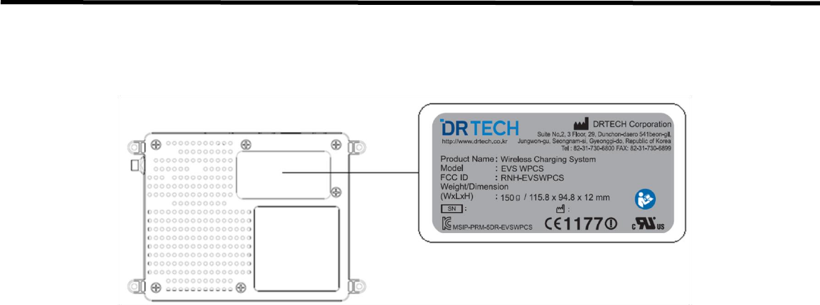
EVS 2430W User’s Manual 11. Regulatory Information
DRT-MAN-091 94
11.3.3. EVS-WPCS
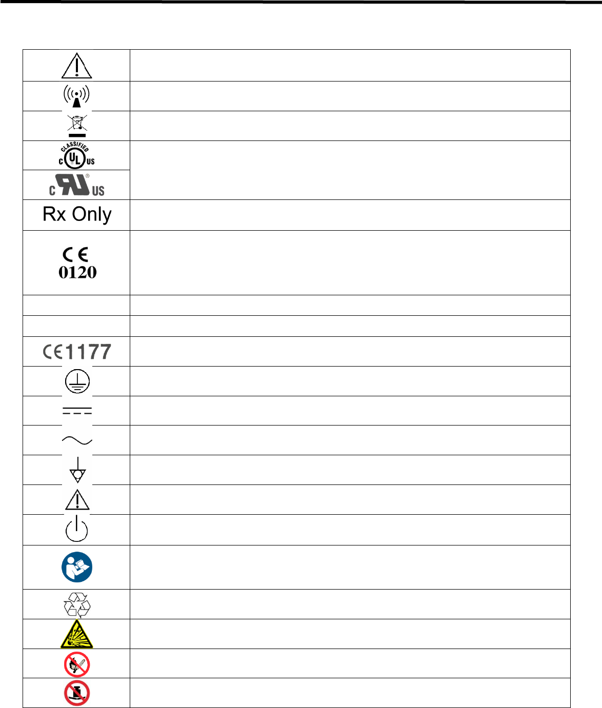
EVS 2430W User’s Manual 11. Regulatory Information
DRT-MAN-091 95
11.3.4. Symbol Description
Caution : Do not jolt or apply excessive load.
Non-ionized radiation
The Waste Electrical and Electronic Equipment Regulations indicates separate collection for
electrical and electronic equipments.
Certification mark that indicates the product complies ANSI/AAMI ES60601-1 (2005) + AMD
1 (2012), CAN/CSA-C22.2 No. 60601-1 (2014) that specifies protection against fire, electric
shock, and mechanical hazards.
For U.S.A standards
Caution : Federal law restricts this device to sale by or on the order of a licensed practitioner.
For European Union (EEC Countries)
Hereby, DRTECH Corporation, declares that this EVS-2430W Wireless is in compliance with
the essential equirements and other relevant provisions of Directive 1999/5/EC and
93/42/EEC. “0120” shows the notified body number for MDD.
MANUFACTUED
Year and Month of production
(S/N)
Serial number in six digits
This mark shows compliance with the equipment with R&TTE Directive 1999/5/EC
Protective Earth (Ground)
Direct Current
Alternating Current
Equipotentially.
Attention, refer to accompanying documents.
Stand-by
Read and understand all instructions and warning labels in the product documentation before
using the equipment.
Keep manual for future reference.
Product contains specific materials that are suitable for recycling.
Should be treated with care because if mistreated it might explode.
Keep away from fire and flames.
Heavy loading is prohibited.

EVS 2430W User’s Manual 11. Regulatory Information
DRT-MAN-091 96
11.4. Guidance and Manufacturer’s Declaration for EMC
Guidelines and Manufacturers : Electromagnetic emission
The EVS 2430W System is used in the following electromagnetic settings. Users of the EVS 2430W System should
check whether their systems are used in these settings.
Emission Test
Compliance
Electromagnetic Setting: Guidelines
RF emission
CISPR 11
Group 1
Since the EVS 2430W System only uses RF energy for internal
functions, it has very low RF emissions and normally causes no
interference to neighboring electronic devices.
RF emission
CISPR 11
Class A
The EVS 2430W System is suitable not only in non-household
facilities but can also be used by directly connecting to the
common low-power network in a building.
Harmonic wave emission
CISPR 11
Class A
Voltage changes
/flicker emission
CISPR 11
Compliance

EVS 2430W User’s Manual 11. Regulatory Information
DRT-MAN-091 97
Full Compliance to the IEC 60601-1-2:2007 and the System’s Tolerance to EM Waves
The EVS 2430W System is used in the following electromagnetic settings.
Users of the EVS 2430W System should check whether their systems are used in these settings.
Tolerance Test
IEC 60601
Test Level
Suitability Level
Electromagnetic Setting : Guidelines
Static electricity
discharge (ESD)
IEC 61000-4-2
+/- 6kV contact
+/- 8kV in the air
+/- 6kV contact
+/- 8kV in the air
The floor should be in wood, concrete or
ceramic tiles. If the floor is in a synthetic
material, the relative humidity should be at
least 30%.
Suitability in
electric over-sprays
IEC 61000-4-4
+/- 2kV power supply
unit line
+/- 1kV input/
output line
+/- 2kV power supply
unit line
+/- 1kV input/
output line
The main power’s quality should be equal to
general commercial or hospital settings.
Surge
IEC 61000-4-11
+/- 1kV line-line
+/- 2kV line-earth
+/- 1kV line-line
+/- 2kV line-earth
The main power’s quality should be equal to
general commercial or hospital settings.
Voltage loss in the
power supply, short
intermittence and
voltage changes
IEC 61000-4-11
<5% UT
(<95%Dip at the UT),
0.5 cycles
40% UT
(60% Dip at the UT),
5 cycles
70% UT
(30% Dip at the UT),
25 cycles
<5% UT
(>95% Dip at the UT),
5 seconds
<5% UT
(<95%Dip at the UT),
0.5 cycles
40% UT
(60% Dip at the UT),
5 cycles
70% UT
(30% Dip at the UT),
25 cycles
<5% UT
(>95% Dip at the UT),
5 seconds
The main power’s quality should be equal to
general commercial or hospital settings.
Note :
Most components in the EVS 2430W
System have their power supplied from the
uninterrupted power supply.
The IEC61000-4-11 only applies to the EVS
2430W System Power Box.
Magnetic field in the
source frequency
(50/60Hz)
IEC 61000-4-8
3A/m
3A/m
The magnetic field in the source frequency
should be equivalent to general commercial
or hospital settings.
Note :
The UT is the main AC voltage before the test standards have been applied.

EVS 2430W User’s Manual 11. Regulatory Information
DRT-MAN-091 98
Guidelines and Manufacturers: Electromagnetic Tolerance
EVS 2430W System is used in the following electromagnetic settings.
Users of the EVS 2430W System should check whether their systems are used in these settings.
Tolerance Test
IEC 60601
Test Level
Suitability
Level
Electromagnetic Setting: Guidelines
Conductive RF
IEC61000-4-6
Radioactive RF
IEC61000-4-3
3Vrms 150kHz-80MH
3v/m 80MHz-2.5GHz
3Vrms
3v/m
When using a portable or a mobile RF communication
equipment, the recommended intervals, which have
been calculated using the equations, should be
maintained. These calculations should be made in
accordance with all of the EVS 2430W System’s parts
(including switches) and its transmitter-receiver’s
frequency.
Recommended intervals :
d = 1.17√p
d = 1.17√p80MHz to 800MHz
d = 2.33√p800MHz to 2.5GHz,
where p is the transmitter-receiver’s maximum power
rating in watts (W) and d is the recommended interval.
The magnetic field strength in the fixed RF receiver,
which has been determined in the EM wave
walkdown1, should be lower than the compliance
standards of each frequency range2.
Interference may occur around the equipment and is
expressed as the symbol shown below.
Note 1 :
The high-frequency range is applied at 80MHz to 800MHz.
Note 2 :
This guideline does not apply in all situations. Electromagnetic waves may be affected
through absorption and reflection from structures, objects and people.

EVS 2430W User’s Manual 11. Regulatory Information
DRT-MAN-091 99
Guidelines and Manufacturers: Electromagnetic Tolerance
It is very difficult to accurately predict the magnetic field strength of wireless (mobile/wireless) telephones, land
mobile radio base stations, amateur wireless channels, AM, FM wireless and TV broadcasting systems. To assess
electromagnetic settings using fixed RF receivers, area walk-down is needed. If the magnetic field strength
measured at the point, where the EVS 2430W System is used, exceeds the applicable RF compliance level, you
should check whether the EVS 2430W System is operating normally. If any performance abnormality is observed,
additional action may be needed such as changing the EVS 2430W System’s direction or location. At the frequency
range between 150kHz and 80MHz, the magnetic field strength should be less than 3v/m.
Recommended Intervals between the EVS 2430W System and the Portable
or Mobile RF Communications Equipment
The EVS 2430W System should be used in an electromagnetic setting where RF communication interferences are
controlled. Users of the EVS 2430W System should maintain the minimum intervals between the System and the
portable or mobile RF communications equipments to prevent electromagnetic interferences more effectively.
Maximum output power rating of the
transceiver - receiver Watts
Interval depending on the transceiver-receiver’s frequency meters
150kHz to 80MHz
d = 1.17√p
80MHz to 800MHz
d = 1.17√p
800MHz to 2.5GHz
d = 2.33√p
0.01
0.117
0.117
0.233
0.1
0.37
0.37
0.737
1
1.17
1.17
2.33
10
3.7
3.7
7.36
100
11.7
11.7
23.3
For maximum power voltages of receivers are not shown in the above list, the recommended interval, d(m), can be
calculated by using the equation used for the receiver’s frequency. The p is the transmitter-receiver’s maximum
power rating in watts (W).
Note 1 :
The high-frequency range is applied at 80MHz to 800MHz.
Note 2 :
This guideline does not apply in all situations. Electromagnetic waves may be affected through absorption and
reflection from structures, objects and people.

EVS 2430W User’s Manual 12. Warranty
DRT-MAN-091 100
12. Warranty
DRTECH Corporation warrants that this product will be free from defects in materials and workmanship for a period of
twelve (12) months from the date of delivery. If any such product proves to be defective during this warranty period,
DRTECH Corporation at its options, will repair the defective product without charge for parts and labor, or will provide
a replacement in exchange for the defective product. In order to obtain service under this warranty, customer must
notify DRTECH Corporation of the defect before the expiration of the warranty period and make suitable arrangements
for the performance of service. Customer shall be responsible for packaging and shipping the defective product to the
service center designated by DRTECH Corporation with shipping charges prepaid. DRTECH Corporation shall pay for
the return of the product to customer if the shipment is to a location within the country in which the DRTECH
Corporation designated service center is located. Customer shall be responsible for paying all shipping charges,
duties, taxes, and any other charges for products returned to any other locations.
This warranty shall not apply to any defect, failure, or damage caused by improper or inadequate maintenance and
care. DRTECH Corporation shall not be obligated to furnish service under this warranty to repair damage resulting
from attempts by personnel other than DRTECH Corporation or its representatives to install, repair, or service this
product, to repair damage resulting from improper use or connection to incompatible equipment or power source; or to
service a product that has been modified or integrated with other products when the effect of such modification or
integration increases the time or difficulty of servicing the product.
THIS WARRANTY IS GIVEN BY DRTECH Corporation WITH RESPECT TO THIS PRODUCT IN LIEU OF ANY
OTHER WARRANTIES, EXPRESS OR IMPLIED. DRTECH Corporation AND ITS VENDOR DISCLAIM ANY IMPLIED
WARRANTIES OF MERCHANTABLILITY OR FITNESS FOR A PARTICULAR PURPOSE. DRTECH Corporation
RESPONSIBILITY TO REPAIR OR REPLACE DEFECTIVE PRODUCTS IS THE SOLE REMEDY PROVIDED TO
THE CUSTOMER FOR BREACH OF THIS WARRANTY. DRTECH AND ITS VENDORS WILL NOT BE LIABLE FOR
ANY INDIRECT, SPECIAL, INCIDENTAL, OR CONSEQUENTIAL DAMAGES IRRESPECTIVE OF WHETHER
DRTECH Corporation OR THE VENDOR HAS ADVANCE NOTICE OF THE POSSIBILITY OF SUCH DAMAGES.
There are no warranties which extend beyond the description mentioned in this document.

EVS 2430W User’s Manual 12. Warranty
DRT-MAN-091 101
Revision History
Revision
Date
Descriptions
00
Feb. 22. 2017
Initial Release

EVS 2430W User’s Manual 12. Warranty
DRT-MAN-091 102
DRTECH Corporation.
Suite No.2 3 Floor, 29
Dunchon-daero541beon -gil,
Jungwon-gu, Seongnam-si, Gyeonggi-do, Republic of Korea
Web Site : http://www.drtech.co.kr
Customer Support Team
E-mail : drtech@drtech.co.kr
Tel : +82 31 730 6805 / Fax : +82 31 730 6899
EXAMION GmbH
Erich-Hherion Stuttgart. 37 in 70736 Fellbach. Germany