DRTECH EVS2430WI Flat Panel Digital X-ray Detector User Manual
DRTECH Corporation Flat Panel Digital X-ray Detector
UserManual.wiki
>
DRTECH
>
EVS2430WI User Manual
User Manual
Navigation menu
Upload a User Manual
Namespaces
Wiki Guide
HTML
PDF
Info
Views
User Manual
Discussion / Help
Navigation
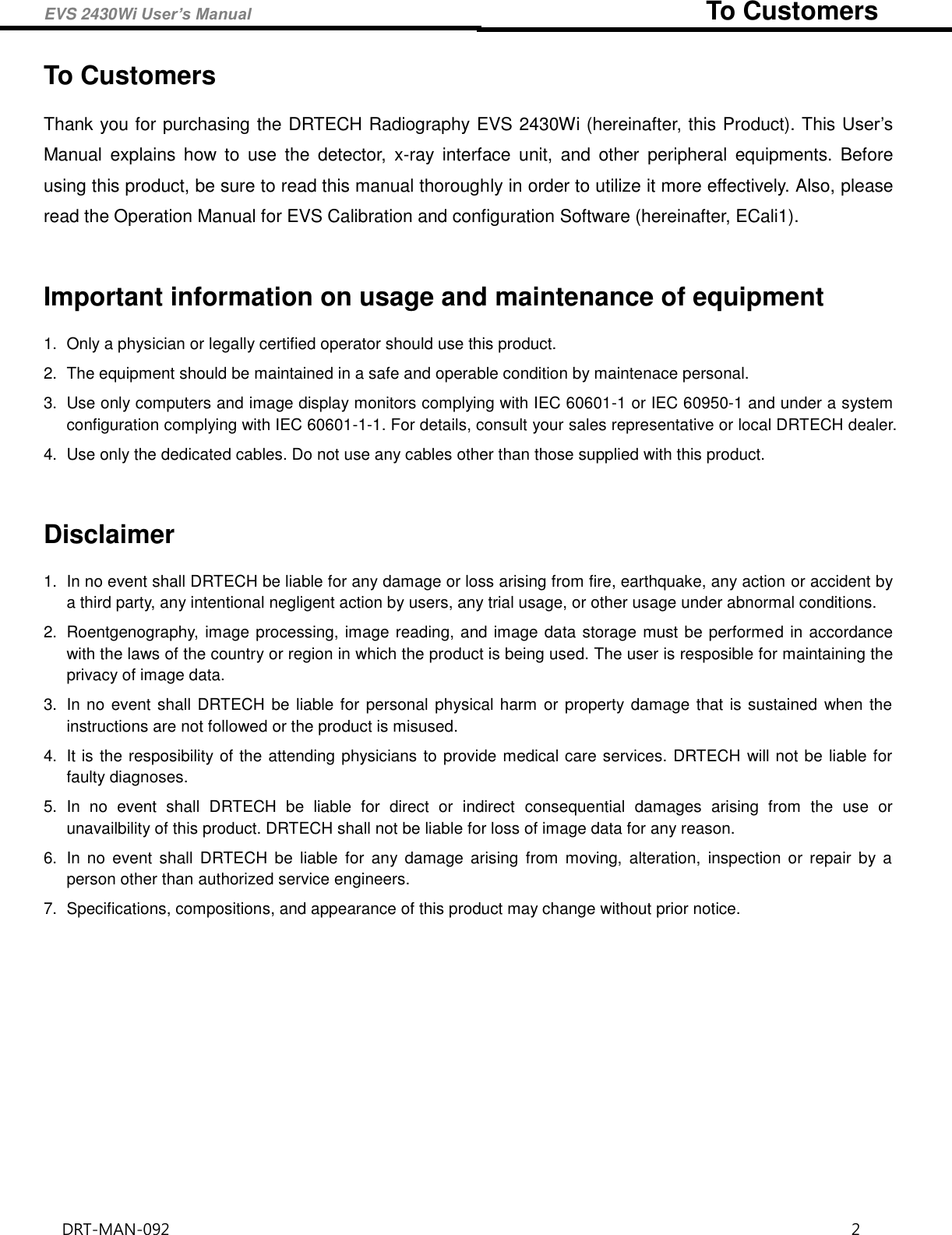

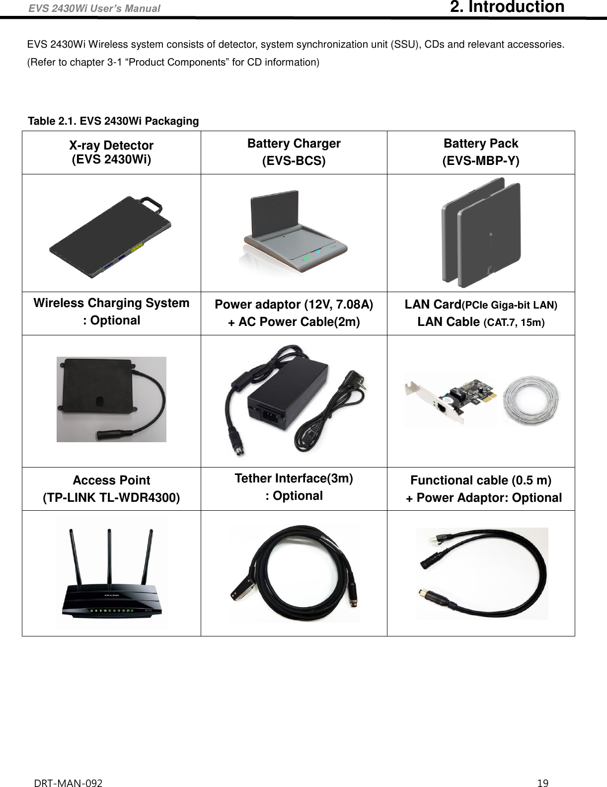
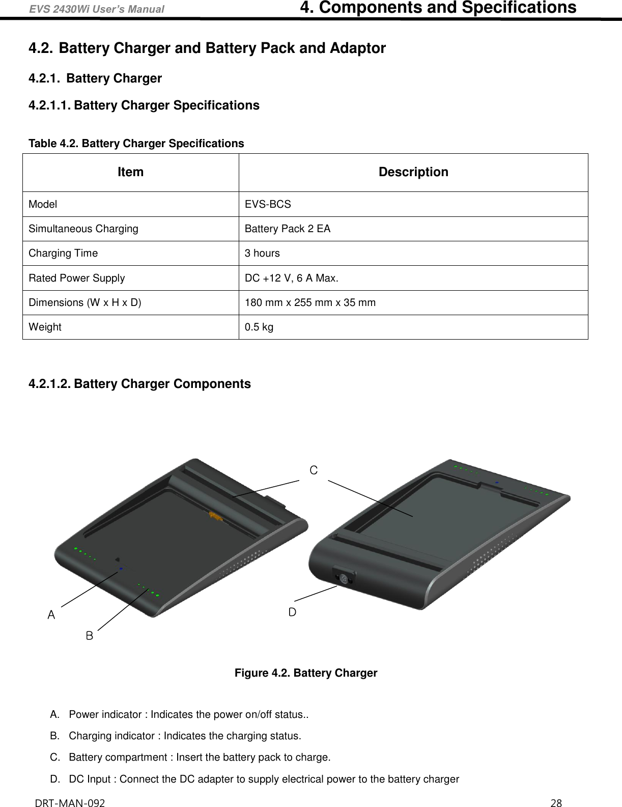
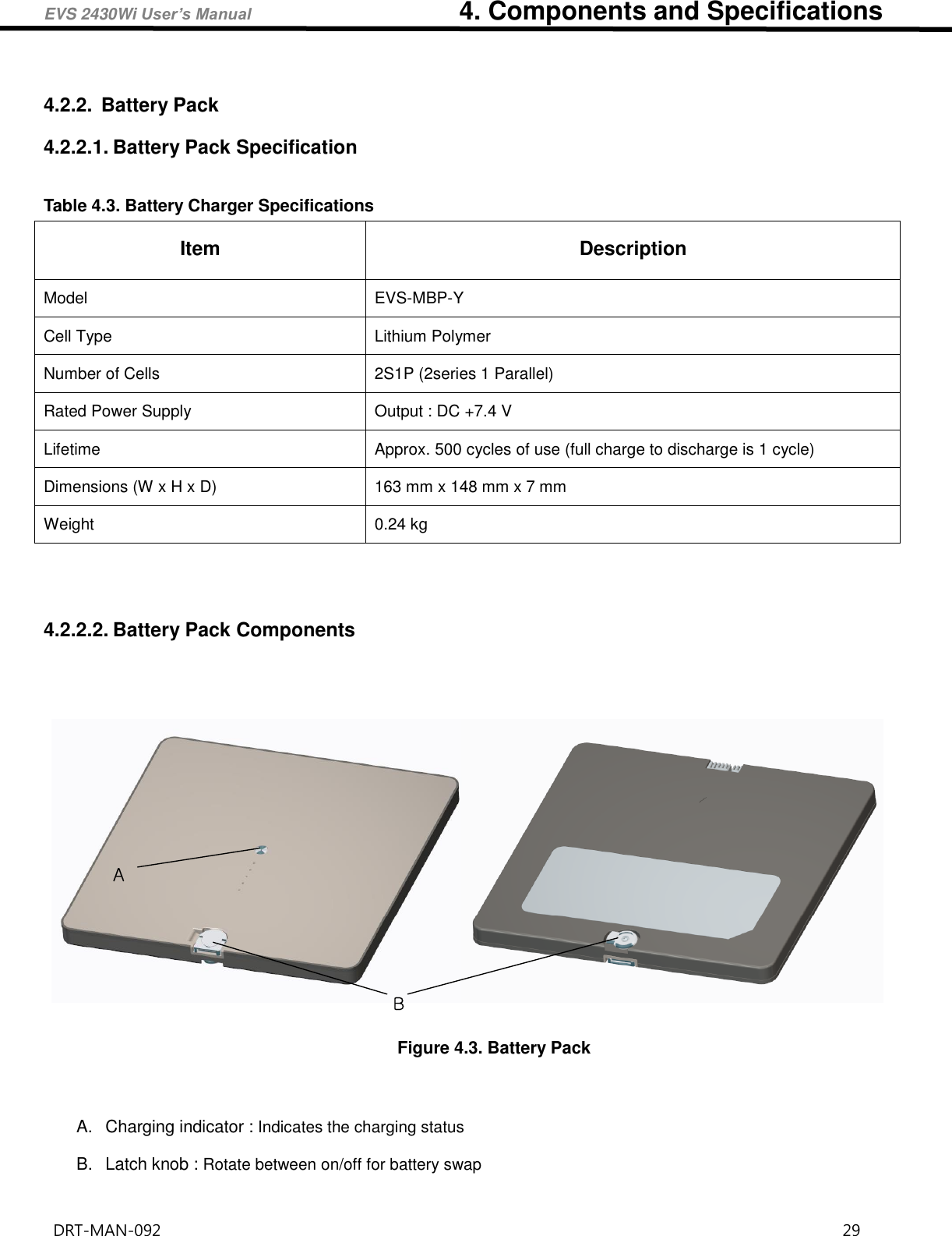
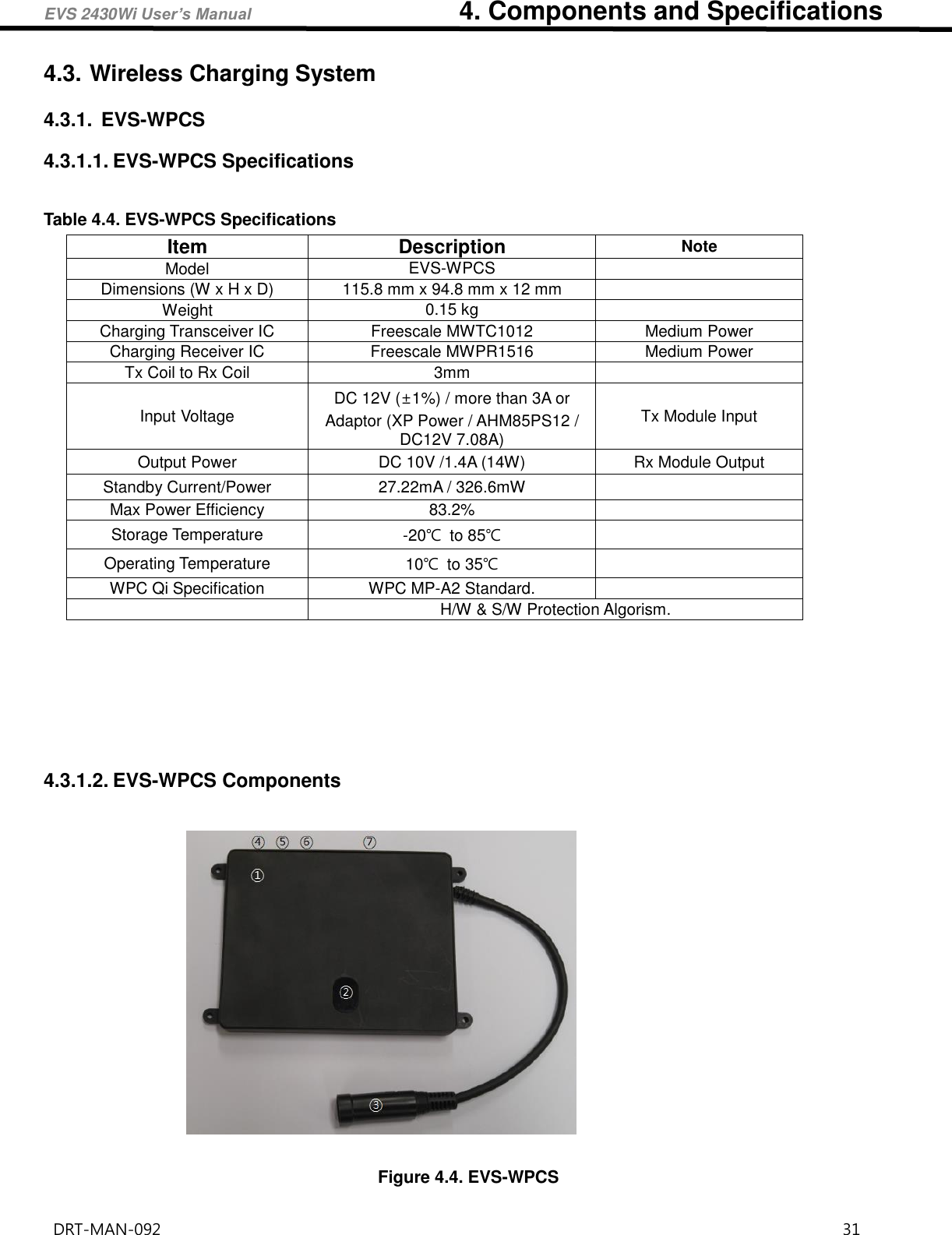
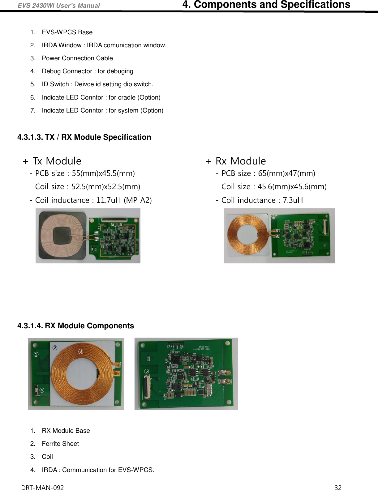
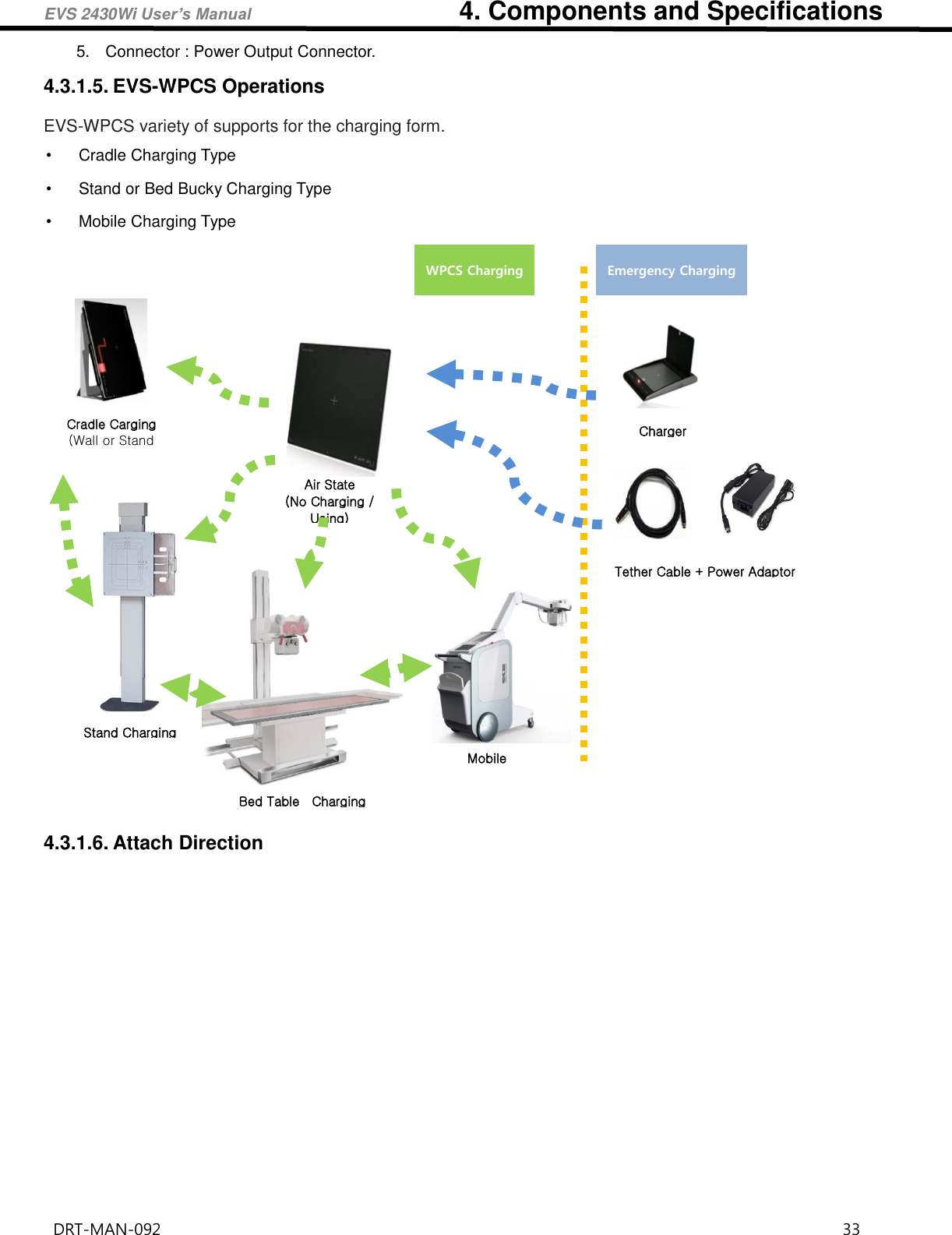
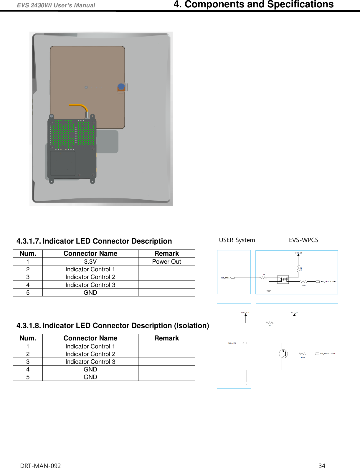
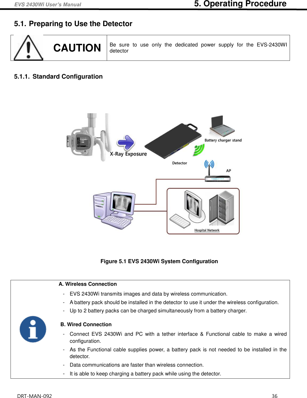
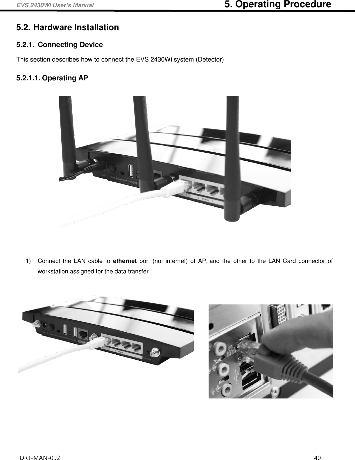
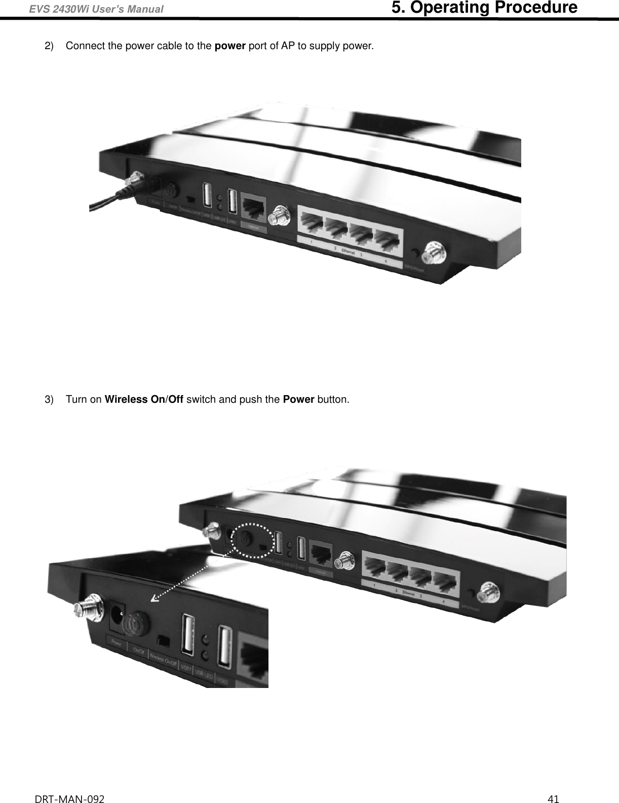
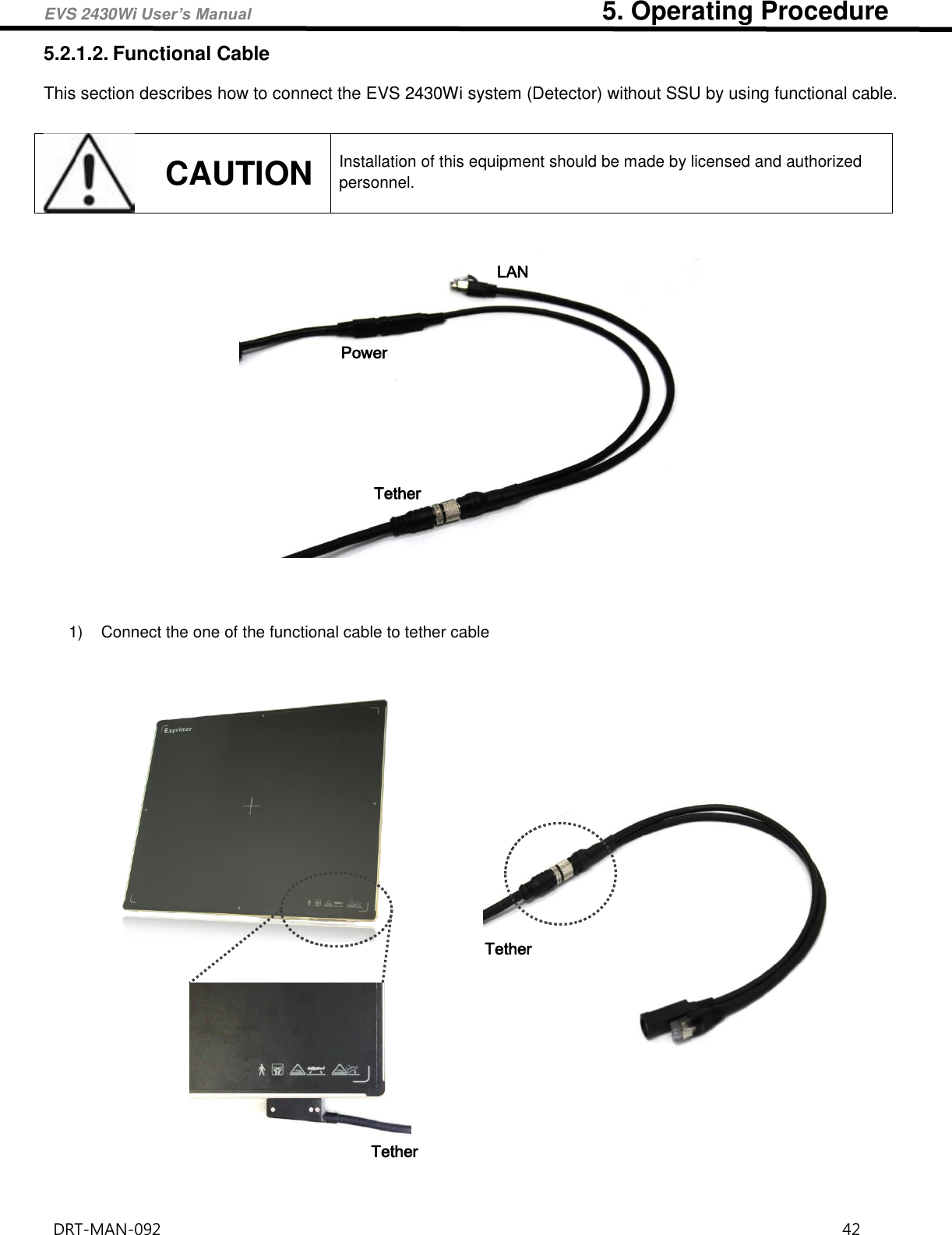
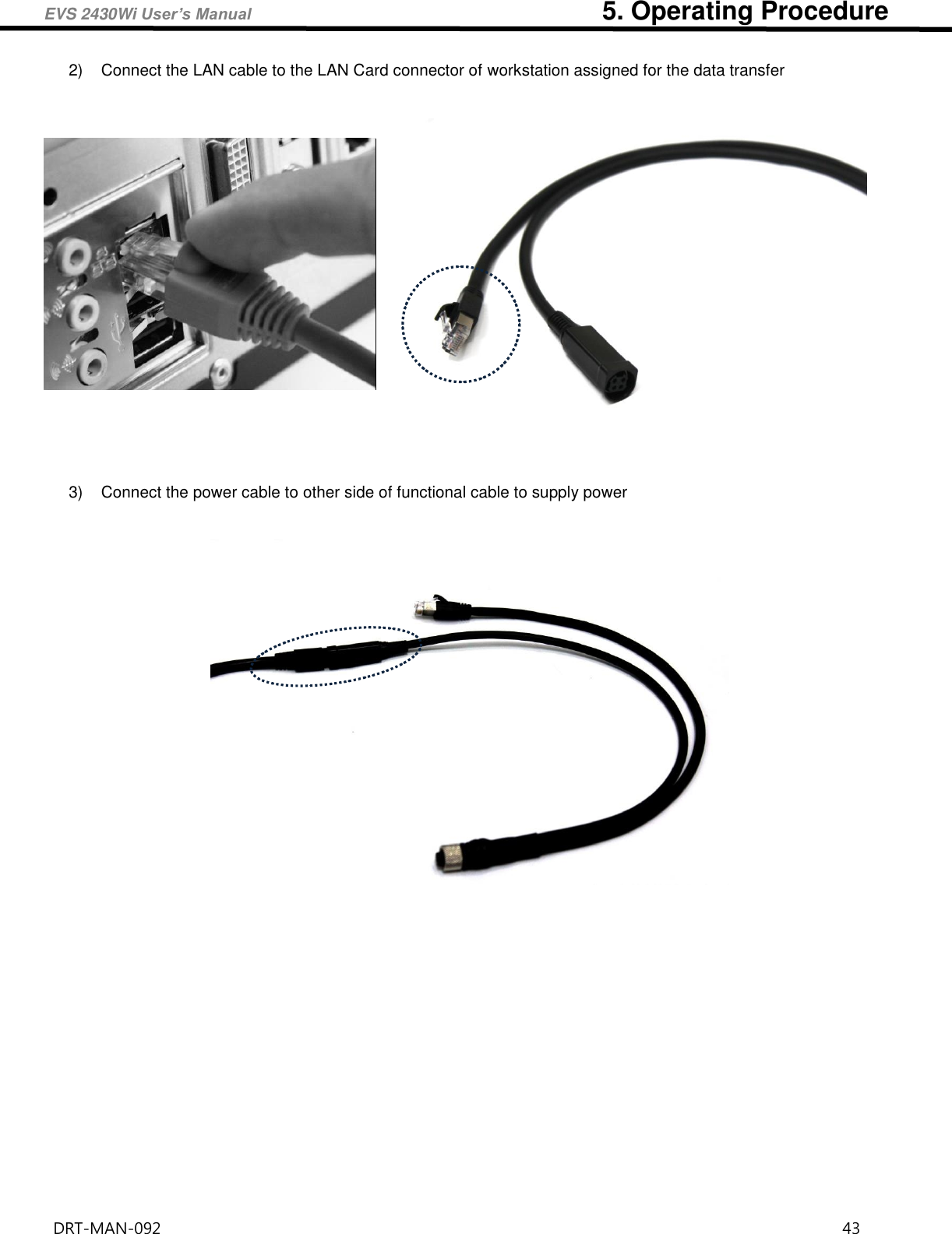
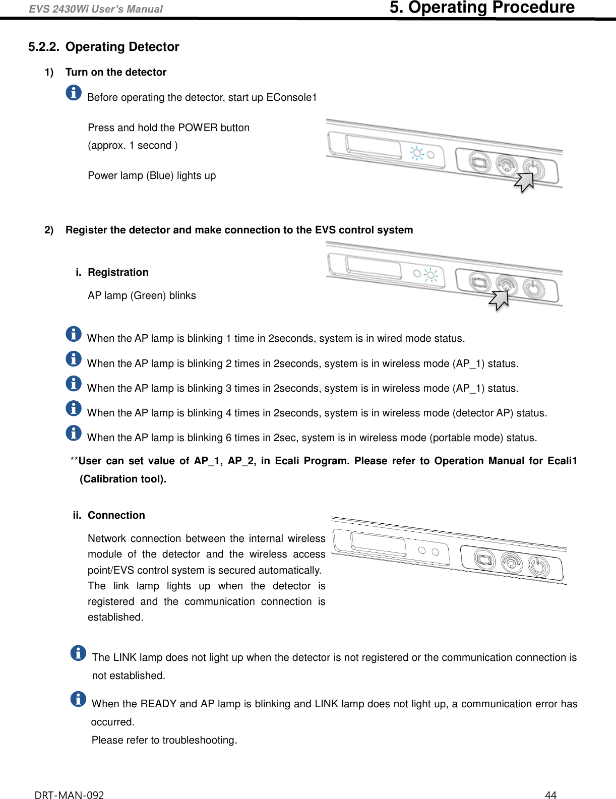
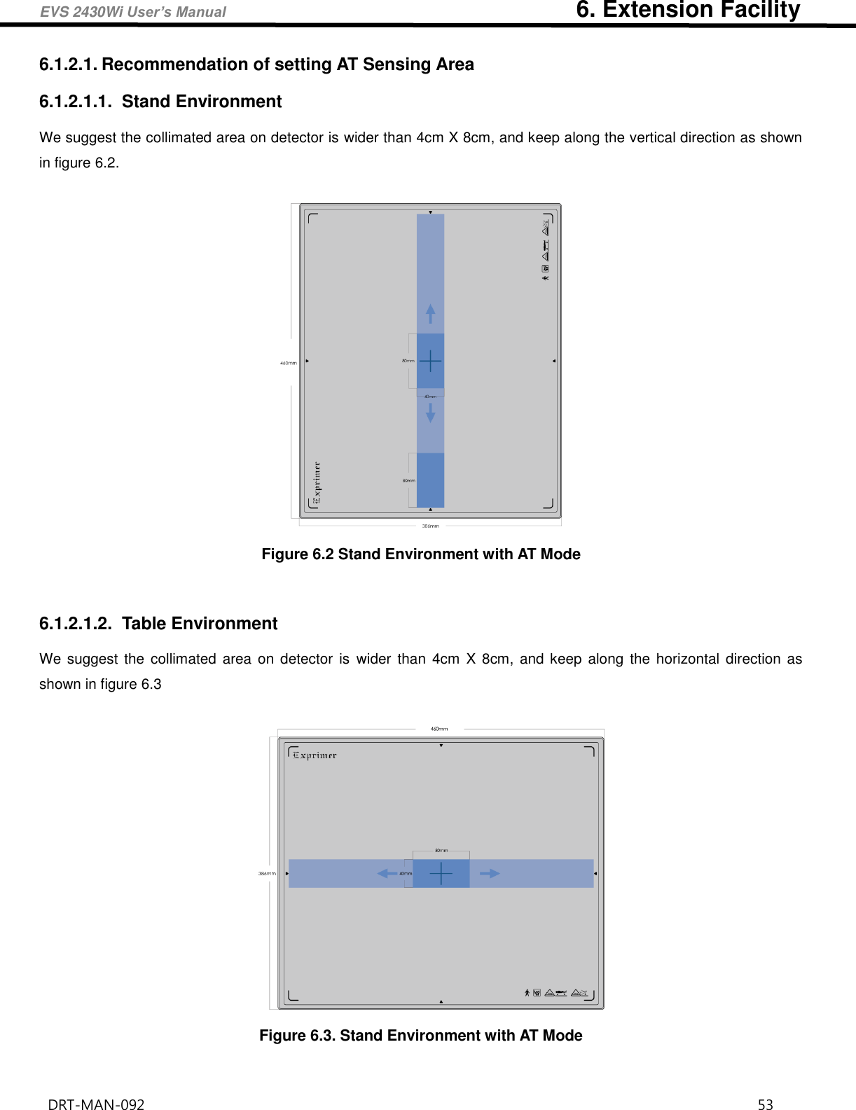
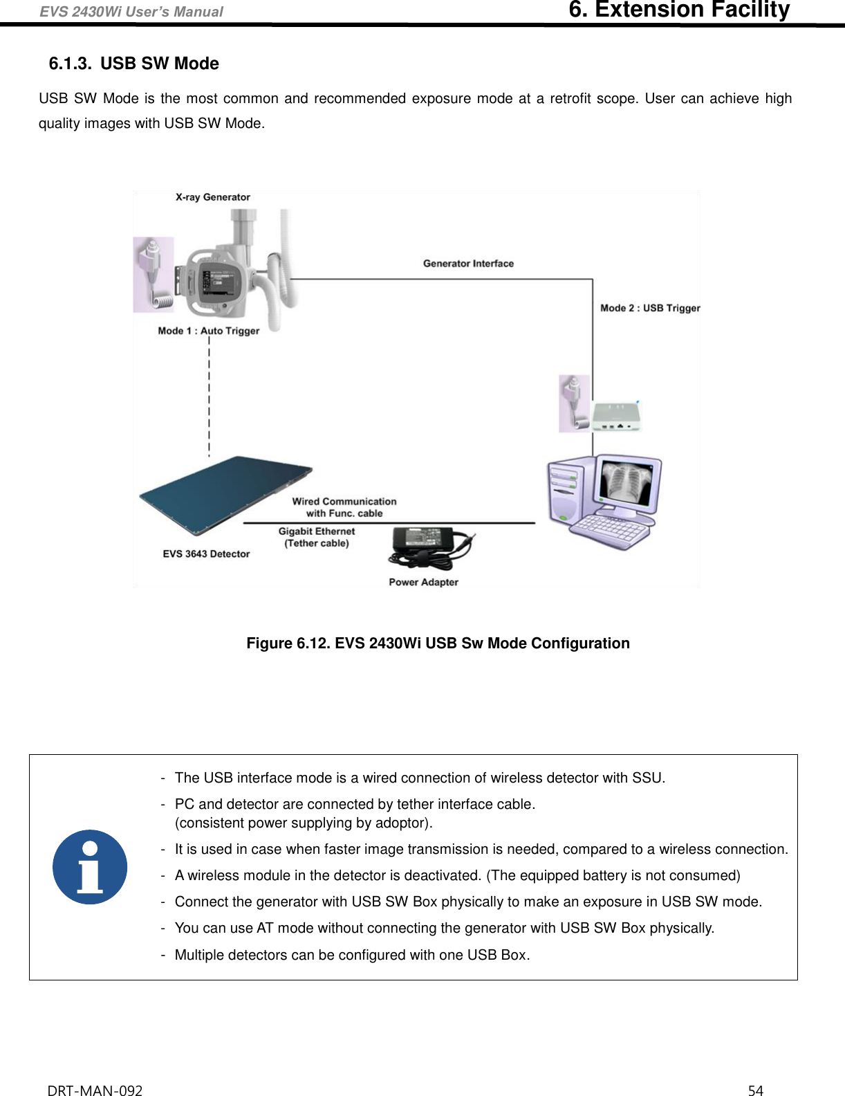
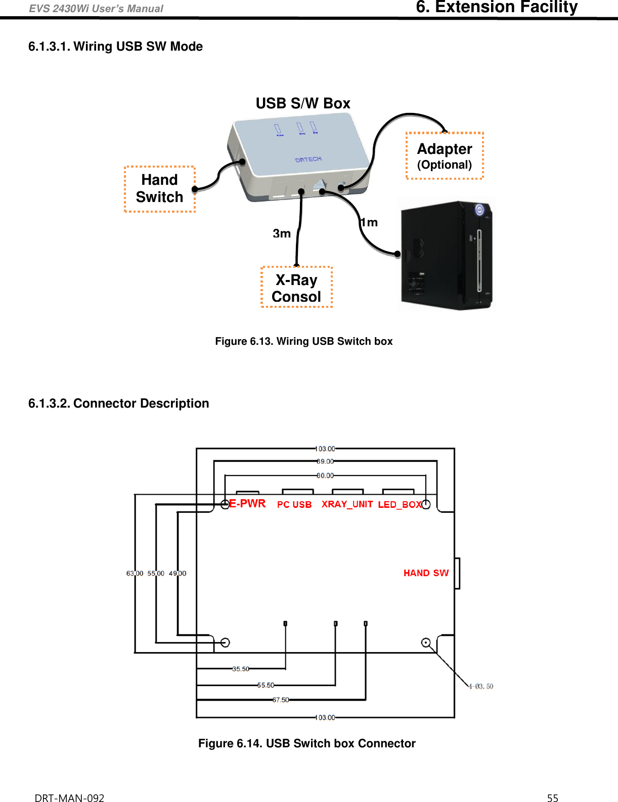
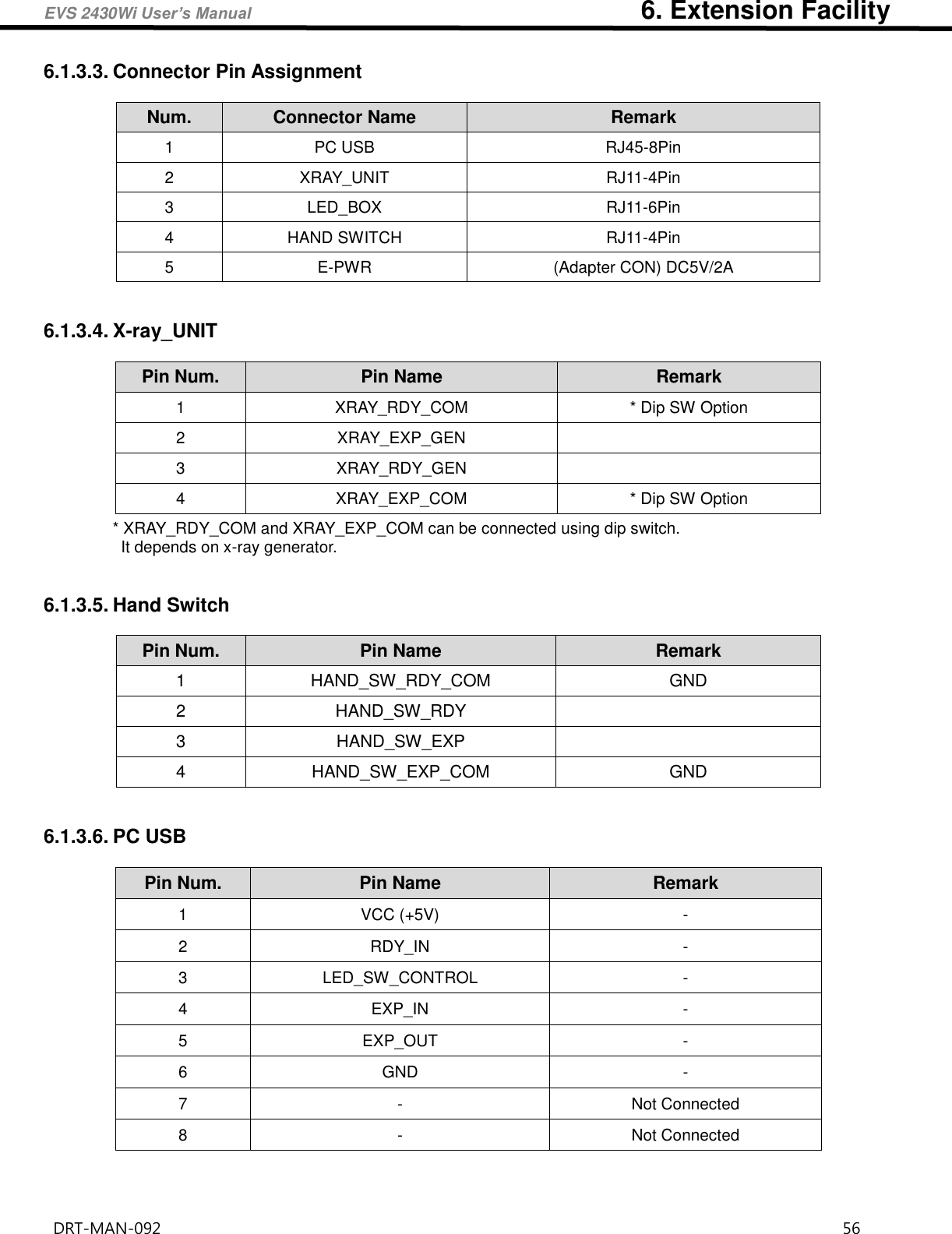
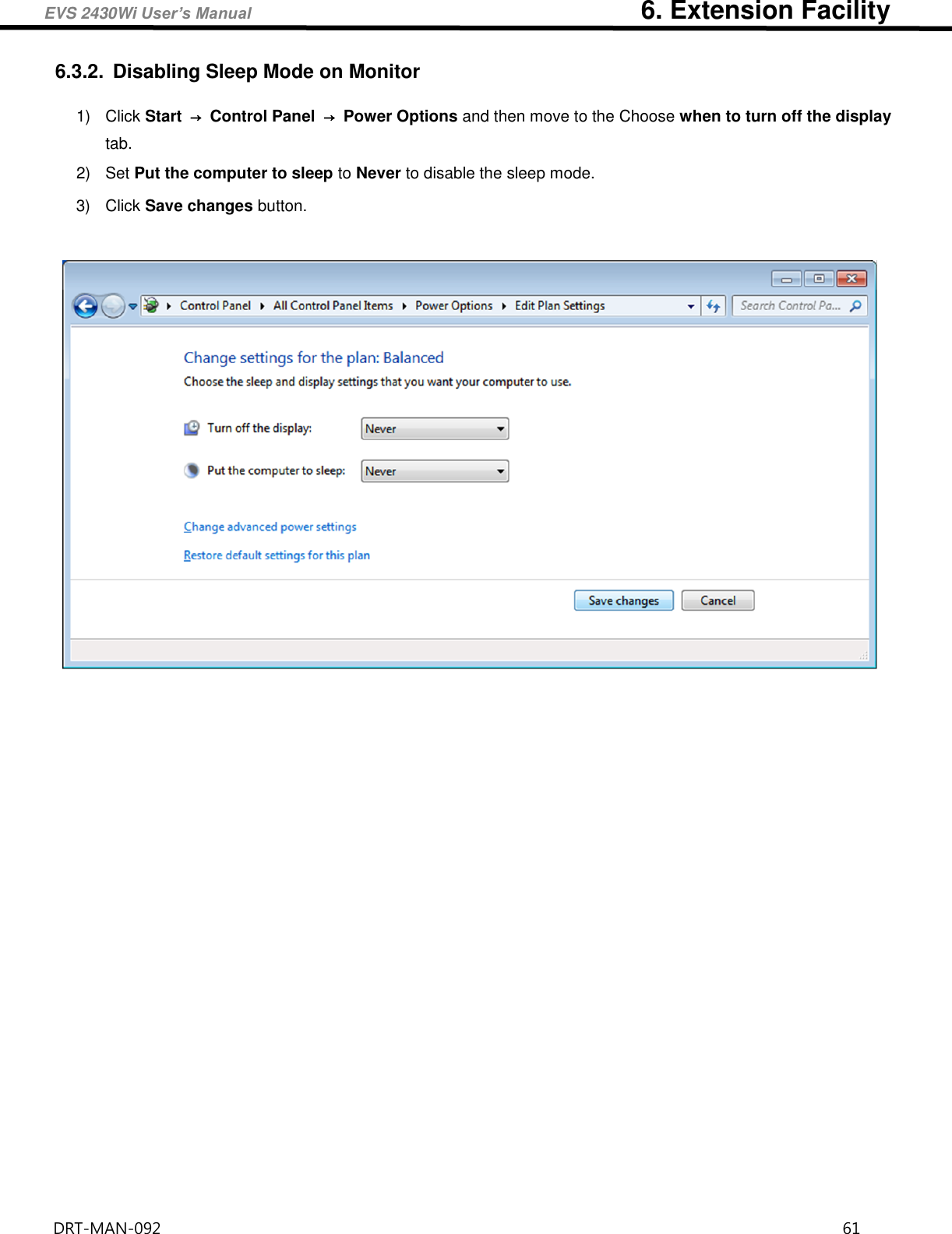
![EVS 2430Wi User’s Manual 4. Components and Specifications DRT-MAN-092 26 4. Components and Specifications 4.1. Detector 4.1.1. Detector Specification Table 4.1. Detector Specifications Item Description Model EVS 2430Wi / EVS 2430GWI Purpose General Radiography Pixel Pitch 76 ɥm Scintillator CsI (Cesium Iodide) / Gadox (Gadolinium Oxysulfide) Image Matrix Size 3072 × 3840 pixels Effective Imaging Area (H x V) 233 x 291 mm Image Acquisition and Transfer Time < 5 sec. Spatial Resolution Min. 6.5 line pair/㎜ Rated Power Supply Wireless (Maker/Mode name/Rating) Wired (Maker/Model name/Rating) Powered by the battery pack (DRTECH Corporation(Powerlinx) / EVS-MBP-Y /7.4V, 4000 mAh) Powered by Power adopter using tether interface (XP Power / AHM85PS12 / DC12V 7.08A) Power Consumption Max. 24 W Network Interface Gigabit Dimensions (㎜) [±0.5 mm] 267.5 (H) × 327.5 (V) × 14.9 (D) Weight 1.8 kg Environmental Requirements Operational Temperature: +10 to +35℃ Humidity: 30 to 85% RH (Without Condensing) Atmospheric pressure: 700 to 1060 hPa Storage and Transportation(unpacked) Temperature: 0 to +40℃ Humidity: 10 to 90% (Without Condensing) Atmospheric pressure: 500 to 1060 hPa †Tether Interface: Allows the detector to communicate with SSU via Ethernet cabling when wireless communications is not available or when higher speed data transfer is necessary](https://usermanual.wiki/DRTECH/EVS2430WI/User-Guide-3403621-Page-26.png)
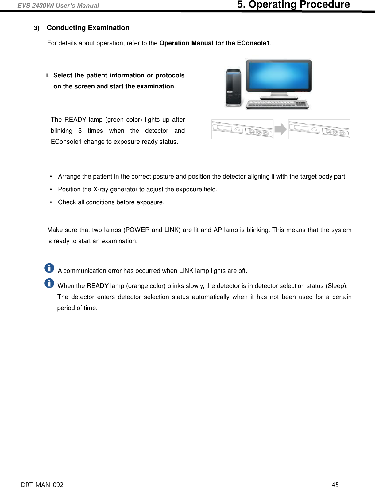

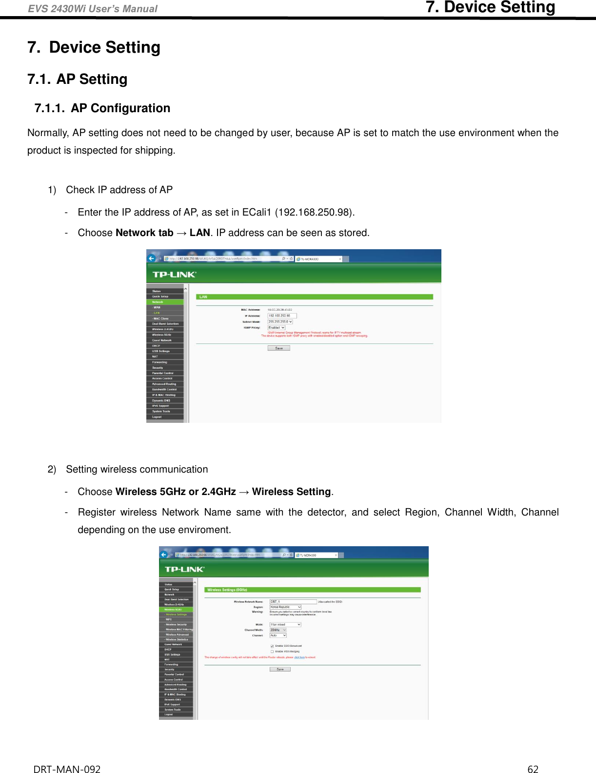
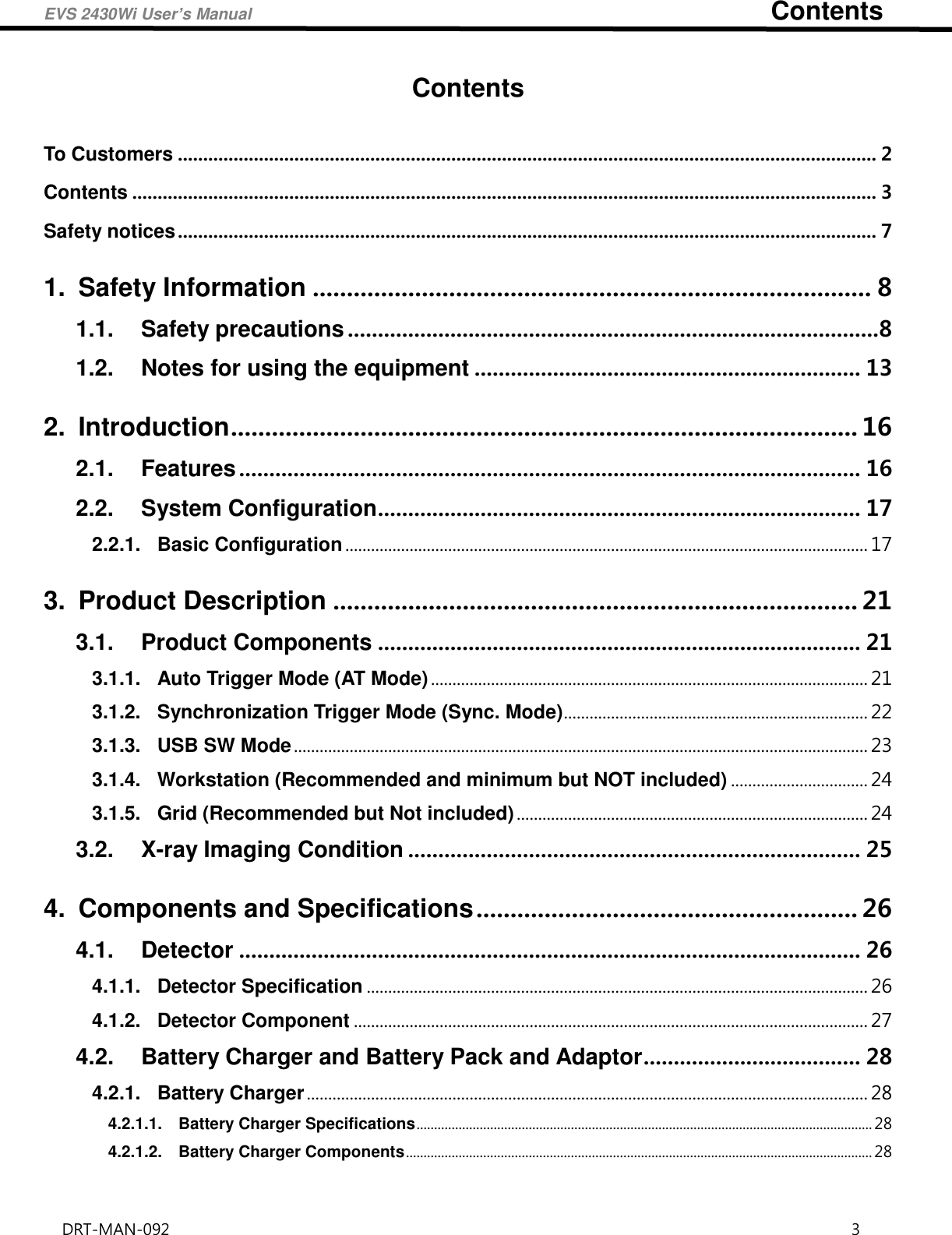
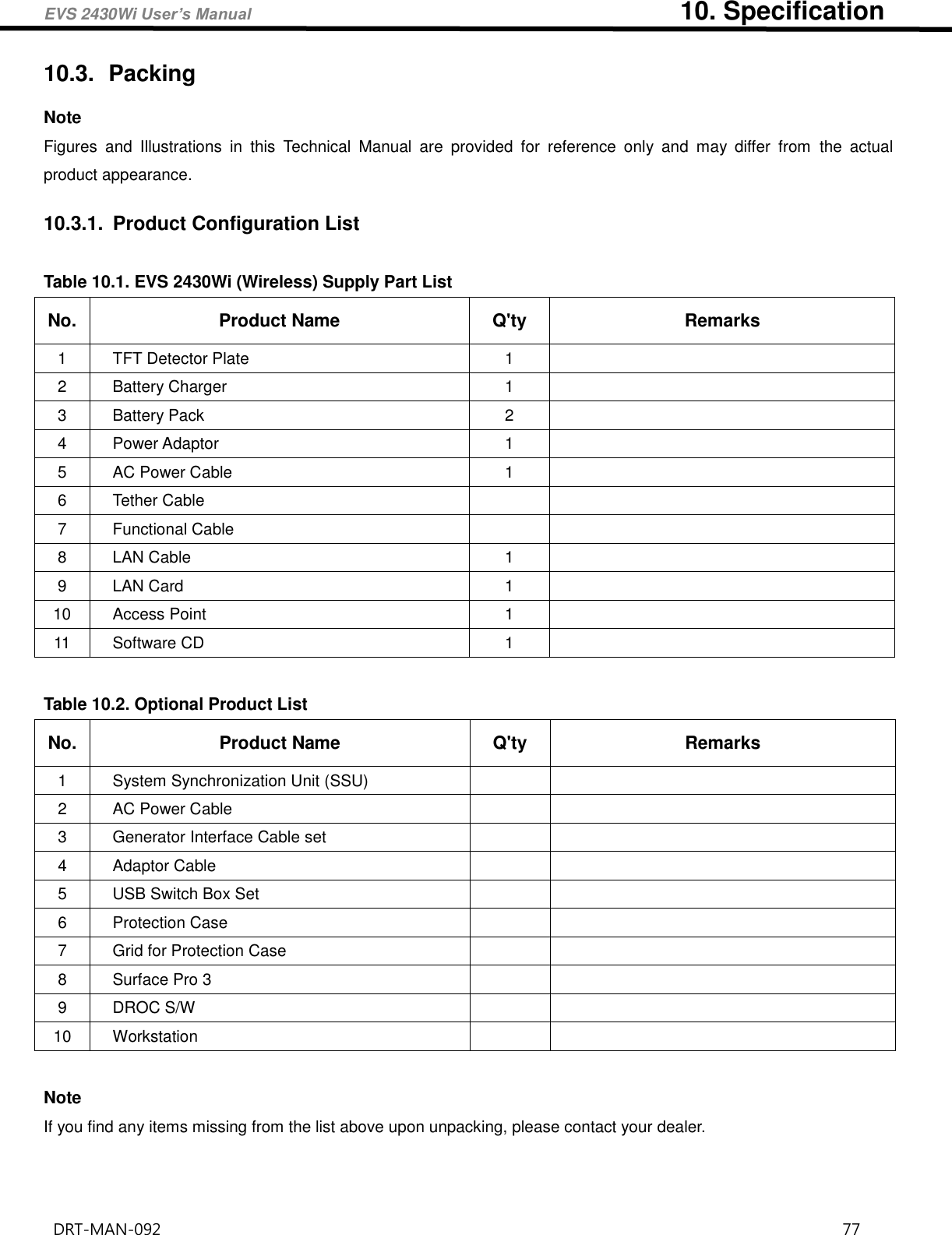
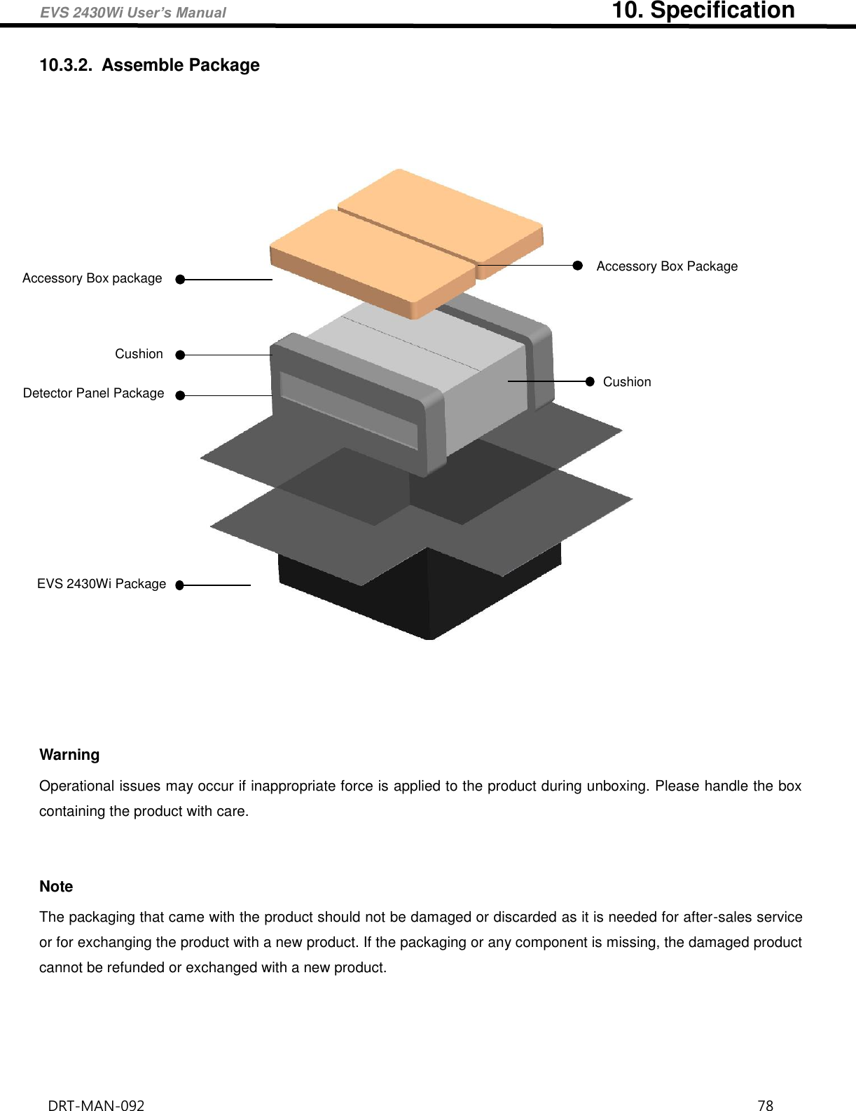
![EVS 2430Wi User’s Manual 10. Specification DRT-MAN-092 72 10. Specification 10.1. Main Specifications 10.1.1. EVS 2430Wi / EVS 2430GWi X-ray Detector [Dimensional Diagram] (Unit mm) Figure 10.1 Detector Dimension](https://usermanual.wiki/DRTECH/EVS2430WI/User-Guide-3403621-Page-72.png)
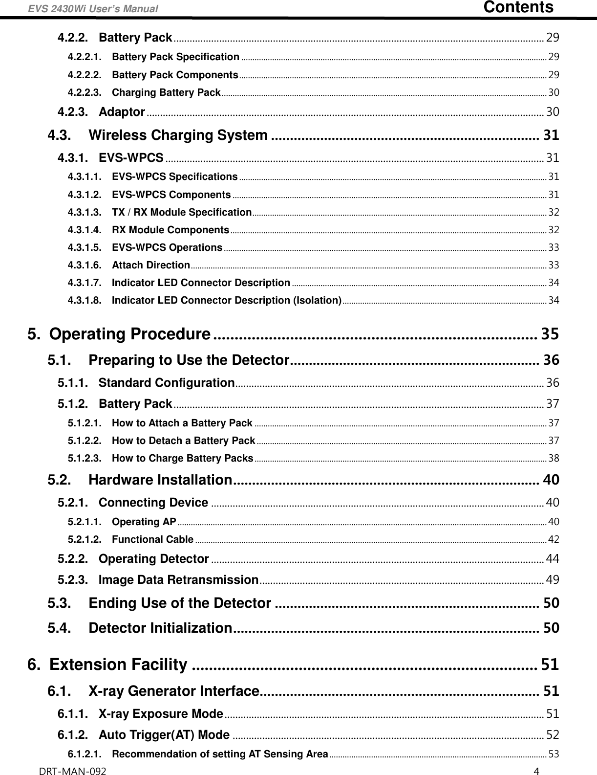
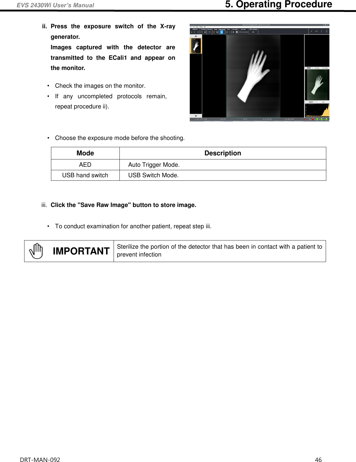
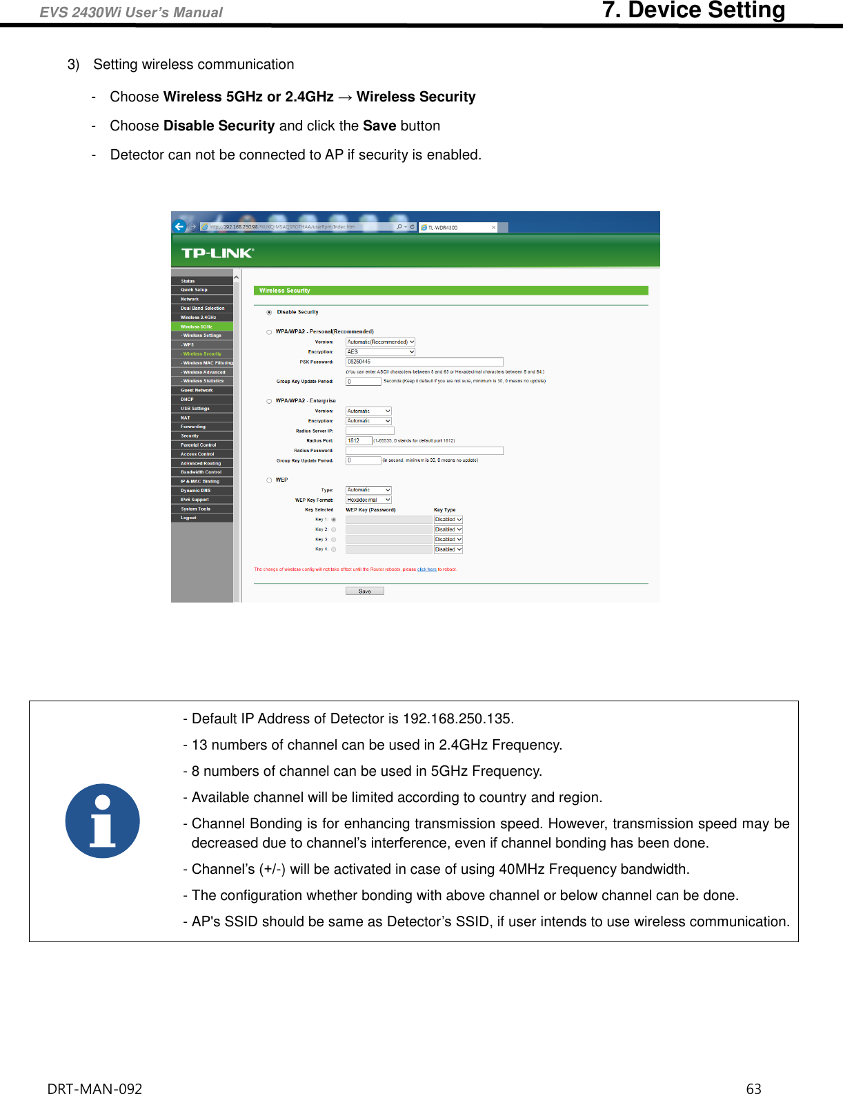
![EVS 2430Wi User’s Manual 10. Specification DRT-MAN-092 73 10.1.2. Battery Charger System [Dimensional Diagram] (Unit mm) Figure 10.2 Battery Charger System Demension](https://usermanual.wiki/DRTECH/EVS2430WI/User-Guide-3403621-Page-73.png)
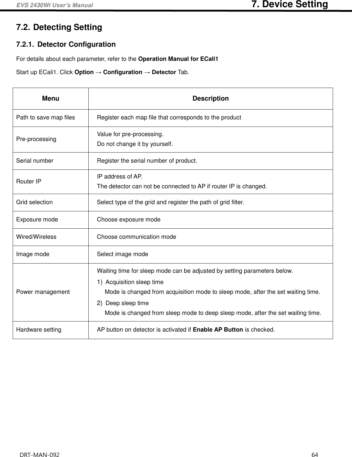
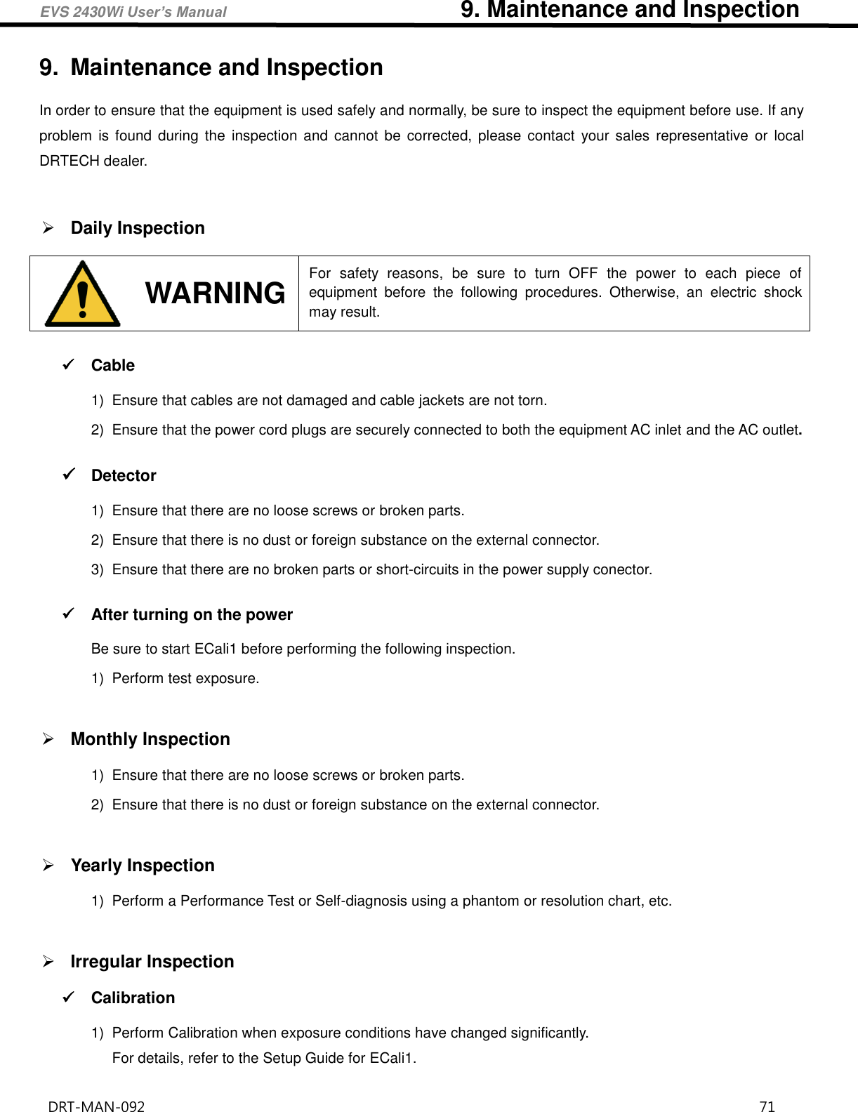
![EVS 2430Wi User’s Manual 10. Specification DRT-MAN-092 74 10.1.3. Battery Pack [Dimensional Diagram] (Unit mm) Figure 10.3 Battery Pack Demension](https://usermanual.wiki/DRTECH/EVS2430WI/User-Guide-3403621-Page-74.png)
![EVS 2430Wi User’s Manual 10. Specification DRT-MAN-092 75 10.1.4. EVS-WPCS [Dimensional Diagram] (Unit mm) Figure 10.4 EVS-WPCS Demension](https://usermanual.wiki/DRTECH/EVS2430WI/User-Guide-3403621-Page-75.png)
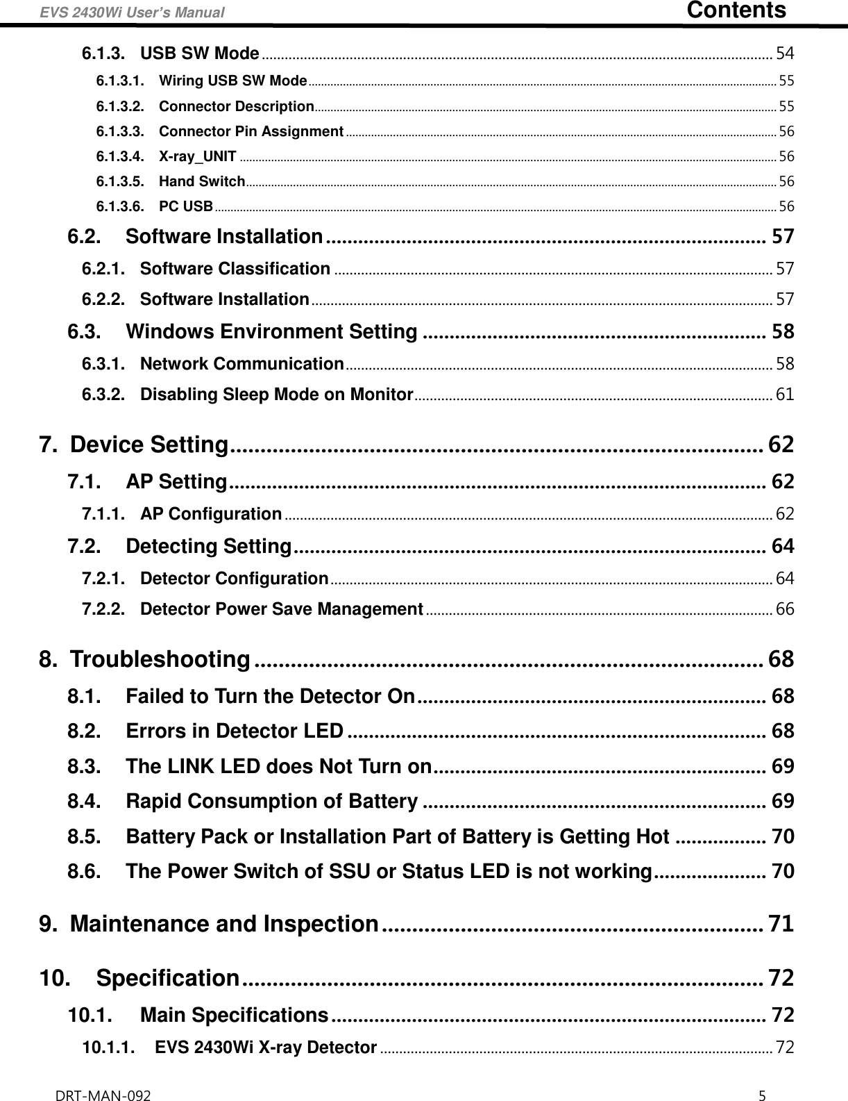
![EVS 2430Wi User’s Manual 10. Specification DRT-MAN-092 79 10.3.3. Detector Panel Package Note • The PCM pack can explode from a hard impact or a contact with a sharp object. • It is non-toxic and may not cause serious harm. However, please take extra precaution as it is a chemical substance, and remember to carefully follow the instructions. • If the inner chemicals get on your body, immediately wash it off thoroughly with clean water. • If the inner chemicals get in your eyes, wash your eyes with tap water for more than 15 minutes and consult your doctor. • If the contents are accidentally ingested, drink two glasses of water (500ml) and consult your doctor. • How to discard the content: Please discard used PCM packs using one of the following methods. • Collect a certain number of packs and send them to the manufacturer. • Treat them in a nearby chemical waste processing facility. Note • PCM Pack [Phase Change Material Pack] • The PCM pack placed in the Bottom cushion is intended to maintain mild temperature over a certain period of time in order to protect Detector from cold weather. • The PCM is originally a liquid, and it begins to emit heat when the box is left for a long period at low temperature below zero Celsius. Its phase changes to a solid state gradually during the heat radiation. • The PCM is a reusable material, which means the solid state PCM returns to its liquid state within approximately 2 hours of heating over 35 degrees Celsius. Utilizing this method, the PCM can be used repeatedly. • The liquid PCM should be stored around room temperature, and can be reused in the same way as the original packing when any transportation is needed. Top cushion PCM Pack 600 Detector PCM Pack Bottom cushion Detector panel Package Inner form](https://usermanual.wiki/DRTECH/EVS2430WI/User-Guide-3403621-Page-79.png)