DRTECH EVS3643 Flat Panel Digital X-ray Detector User Manual EVS 3643
DRTECH Corporation Flat Panel Digital X-ray Detector EVS 3643
DRTECH >
User Manual

DRTECH EVS 3643 System
Safety and Regulatory Information
with User’s Manual

EVS 3643 User’s Manual To Customers
10-EVS1MADB002 2
Thank you for purchasing the DRTECH Radiography EVS 3643 (hereinafter this Product). This User’s Manual
explains how to use the detector, x-ray interface unit, and other periperal equipment. Before using this product,
be sure to read this manual thoroughly in order to utilize it more effectively. Also, read the Operation Manual for
EVS Calibration and configuration Software (hereinafter ECali1).
Important information on usage and management of equipment
1. Only a physician or legally certified operator should use this product.
2. The equipment should be maintained in a safe and operable condition by maintenace personal.
3. Use only computers ans image display monitors complying with IEC 60601-1 or IEC 60950-1 and under
asystem configuration complying with IEC 60601-1-1. For details, consult your sales representative or local
DRTECH dealer.
4. Use only the dedicated cables. Do not use any cables other than those supplied with this product.
Disclaimer
1. In no event shall DRTECH be liable for any damage or loss arising from fire, earthquake, any action or
accident by a third party, any intentional negligent action by users, any trial usage, or other usage under
abnormal conditions.
2. Roentgenography, image processing, image reading, and image data storage must be performe in
accordance with the laws of the country or region in which the product is being used. The user is resposible
for manufacturing the privacy of image data.
3. In no event shall DRTECH be liable for personal physical harm or property damage that is sustained when
the instructions are not followed or the product is misused.
4. It is the resposibility of the attending physicians to provide medical care services. DRTECH will not be liable
for faulty diagnoses.
5. In no event shall DRTECH be liable for direct or indirect cosequential damages arising from the use or
unavailbility of this product. DRTECH shall not be liable for loss of image data for any reason.
6. In no event shall DRTECH be liable for any damage arising from moving, alteration, inspection or repair by a
person other than authorized service engineers.
7. Specifications, composition, and appearance of this product may change without prior notice.

EVS 3643 User’s Manual Contents
10-EVS1MADB001 5
To Customers…………………………………………………………….……………………………… 2
Contents……………………………………………………………………………………………..…… 3
Conventions………………………………………………………………….……………………..…… 5
1. Safety nformation……………….…………………………………………….…….6
1-1. Safety precautions……………………………………………………………………………..6
1-2. Notes for using the equipment……………………………………………………..……..….10
2. Introduction…………………………………………………………………...……..12
2-1. Features……………………………………………………………….……………………….12
2-2. Intended use…………………………………………………………. ………..…………..….12
2-3. System configuration………………………………………………………………..………..13
3. Product description………………………………………………………………..14
3-1. Product components………………………………………….…………..….…….…..……..15
3-2. X-ray imaging condition…….………………….……………………………..…..…………16
4. Parts name and functions………………………………………………………..17
4-1. Detector specification………………….……………………………………….…..17
4-2. Detector component………………….……………………………………….…..18
4-3. Detector dimension………………….……………………………………….…..19
4-4. SSU (System syncronization unit)……………………………………..………….………20
4-5. Wireless acess point………………………………………………………………………..20
5. Operating pocedure…….………………………………………………………..22
5-1. Preparing to use the detector……………………….…………………………………….…..23
5-2. Operating the detector…….………………………………………………..………….………23
5-3. Ending use of the detector…………………………………………………………………….27
5-4. Detector status list………………………………………………………………………………27

EVS 3643User’s Manual 5. Operating procedure
10-EVS1MADB001 4
6. Extension facility….…….………………………………………………………..28
6-1. Using the wirless detector with other EXPRIMER series detectors in a same system …28
6-2. Sharing the wireless detector among different systems………………..………….………29
6-3. AED mode……………………………………….………………………………………………30
6-4. Wiring connections……………………………………….………………………………….31
7. How to Install………………………..…….….…….………………………………32
8. Troubleshooting….……….….…….………………………………………………89
9. Maintenace ………….….…….……………………………………………………..90
10. Specification…………………………………………………………………………91
10-1.Main specifications……………………………………………………………………………91
EVS 3643 Detector…………………………………………………………………………….91
SSU(system syncronization unit)…………………………………………………………….92
10-2. Chrateristicss………………………………………………………………………………….93
11. Regulatory information………….….….…………………………………………94
11-1. Medical equipment safety standards……………………………………………………….94
■ Medical equipment classification………………………………………………………….94
■ Product safety standards…………………………………………………………………..94
11-2. Radio frequency (RF) compliance information………………………………………………95
Declaration comforty………………………………………………………………………….95
11-3. Labels and markings on the equipment………………………………………………………99
■ Detector………………………………………………………………………………………99
■ Other components of the EVS 3643 system……………………………………..101
11-4. Guidance and manufacturer’s declaration for EMC………………………………………103
Electromagnetic emissions……………………………………………………………………103
Electromagnetic immunity…………………………………………………………………103
Electromagnetic separation distances………………………………………………………103
12. Warranty ………….….…….………………………………………………………..106
EVS 3643 User’s Manual
Contents
10-EVS1MADB001 5
Safety notices
The following safety notices are used to emphasize certain safety instructions. Follow the safety instructions in
this user’s maual along with warning and cautions sysbols. Ignoring such warnings or cautions while handling
the product may results in serious injury or accient. It is important for you to read and understand the contents of
this users manual before attemting to use the product.
WARNING This notice used to idendifiy conditions under which improper use
of the product may cause death or serious personal injury.
CAUTION This notice used to idendifi\y conditions under which improper
use of the product may cause minor personal injury.
CAUTION This notice used to idendifiy conditions under which improper use
of the product may cause property damage.
Prohibited
This is used to indicate a prohibited operation.
This is used to indicate an action that must be performed.
IMPORTANT
This is used to indicate important operations and restrictions.
Be sure to read this notice to prevent property damage or malfunction.
This is used to indicate operations for reference and complementary
information.
User are recommended to read this notice
EVS 3643 User’s Manual 1. Safety information
10-EVS1MADB001 6
1-1. Safety precautions
Follow these safeguards and properly use the equipment to prevent injury and damage to any equipment/data.
WARNING
Installation and environment of use
Prohibited
- Do not use or stroe the equipment near flammable chemical such as alcohol, thinner,
benzine, etc.
If chemicals are spilled or evaporate, it may result in fire or electric shock through contact
with electric parts inside the equipment. Also, somedisinfectants are flammable. Be sure to
take care when using them.
- Do not connect the equipment with anything other than specified.
Doing so may result in fire or electric shock.
Power supply
Prohibited
- Do not use operate the equipment using any type of power supply other than the one
indicated on the rating label.
Otherwise, it may result in fire or electric shock.
- Do not handle the equipment with wet hands.
You may experience an electric shock that could result in death or serious injury.
- Do not place heavy object such as medical equipment on cables and cords, or do not
pull, bend, bundle, or step on them to prevent their sheath from being damaged, and
do not alter them neither.
Doing so may damage the cords which could result in fire or electric shock.
- Do not supply power to more than one of equipment using the same AC outlet.
Doing so may result in fire or electric shock.
- Do not turn on the system power when condensation has formed on the equipment.
Doing so may result in fire or electric shock.
- Do not connect a multiple portable socket-outlet or extension cord to the system.
Doing so may result in fire or electric shock.
- Securely plug the power cord into the AC outlet.
If contact failure occurs, or if dust or metal objects come into contact with the exposed metal
prong of the plug, fire or electric shock may result.
- Be sure to turn OFF the power to each of equipment before connecting or
disconnecting the cords.
Otherwise, you may get an electric sock that could result in death or serious injury.
- Be sure to hold the plug or connector to disconnect the cord.
If you pull the cord, the core wire may be damaged, resulting in fire or electric shock.
EVS 3643 User’s Manual
1. Safety information
10-EVS1MADB001 7
WARNING
Handling
The system, in whole or in part, cannot be modified in any way without written approval from DRTECH.
Prohibited
- No modification of this equipment is allowed
- Never disassemble or modify the equipment.
Doing so may result in fire or electric shock. Also, since the equipment incorporates parts
that may cause electric shcok as well as other hazardous parts, touching them may cause
death or serious injury.
- Do not place anything on top of the equipment.
The object may fall and cause an injury. Also if metal objects such as needles or clips fall
into he equipment, or if liquid isspilled, if may result in fire or electric shock.
- Do not hit or drop the equipment.
The may be damaged if it recieves a strong jolt, which may result in fire or electric shock if
the equipment is used without geing repaired.
- Have the patient take a sixed posture and do not let patient touch parts unnecessarily.
If the patient touched connectors or switches, it may result in electric shock or malfunction of
the equipment.
When a problem occurs
- Should any of the following occur, immediately turn OFF the power to each piece of
equipment, unplug the power cord from the AC outlet, and contact your sales
representative or local DRTECH dealer:
When there is smoke, an odd smell or abnormal sound
When liquid has been spilled into equipment or metal object has entered through an
opening.
When the equipment has been droppen and is damaged.
Maintenance and inspection
Prohibited
- When the equipment is going to be cleaned, be sure to turn OFF the power of each
equipment, and unpulg the power cord from the AC outlet. Never use alcohol,
benzine, thinner or any other flammable cleaning agent.
Othewise, it may result in fire or electric shock
- Clean the plug of the power cord periodically by unplugging it from the AC outlet and
removing dust or dirt from the plug, its periphery and AC oulet with a dry cloth.
If the cord is kept plugged in for a long time in a dusty, humid or sootyplace, dust around the
plug will attract moisture, and this could cause insulation failure that could result in a fire.
- For safety reasons, be sure to turn OFF the power to each piece of equipment when
the insections indicated in this manual are going to be performed..
Otherwise, electric shocks may occur.
EVS 3643 User’s Manual
1. Safety information
10-EVS1MADB001 8
WARNING
Installation and environment of use
- Do not install the equipment in any of the locations listed below. Doing so may result
in failure or malfuction, equipment faillng, or fire or injury.
ㆍClose to facilities where water is used
ㆍwhere it may be exposed to direct sunlight
ㆍClose to the air outlet of an air-conditioner or ventilation equipment
ㆍClose to a eat source such as a heater
ㆍwhere the power supply is unstable
ㆍIn a saline or sulfurous environment
ㆍwhere temperature or humidity is high
ㆍwhere there is freezing or condensation
ㆍIn area prone to vibration
ㆍOn an incline or in an unstable area
- Because the equipment cable is long, take care that cables do not become tangled
during use. Also, be careful not to get your feet caught in the cable.
Otherwise, it may cause a malfunction of the equipment or the injury of the user due to
tripping over the cable.
- Non-medical equipment such as the battery charger, and access point unit cannot be
used in patient’s vicinity.
Patient Vicinity
Power supply
- Always connectthe three-core power cord plug to a grounded AC power outlet.
- To avoid the risk of electric shock, this equipment must only be connected to a
supply mains with protective earth”.
- To make it easy to disconnect the plug at any time, avoid putting any obstacles near
the outlet. Otherwise, it may not be possible to disconnect the plug in an emergency.
- Be sure to ground the equipment to an indoor grounded connector. Also, be sure to
connect all the grounded for the system to a common ground.
- Do not use any power source other than the one provided with this equipment.
Otherwise, fire or electric shock may be caused due to leakage
Handling
- Do not spill liquid or chemicals onto the equipment or, in cases where the patient is
injured, allow it to come in contact with blood or body fluids.
Doing so may result in fire or electric shock.
In such a situation, protect the equipment with a disposable covering as necessary.
- Turn OFF the power to each piece of equipment for safety when not belong used.
EVS 3643 User’s Manual
1. Safety information
10-EVS1MADB001 9
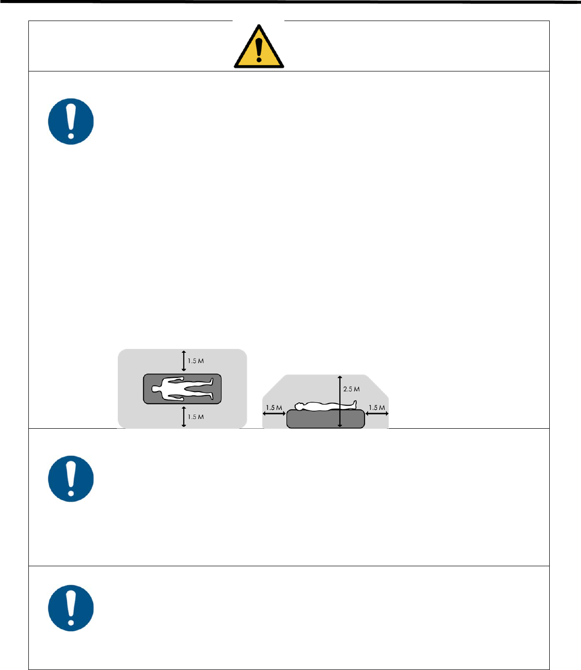
CAUTION
Handling the equipment
The Equipment must be handled with care to avoid personal injury or damage to the internal image sensor.
- Handle the equipment carefully.
- Do not submerge the equipment in water
- The internal image sensor may be damaged if something hits against it, or if it is
dropped, or recieves a strong jolt.
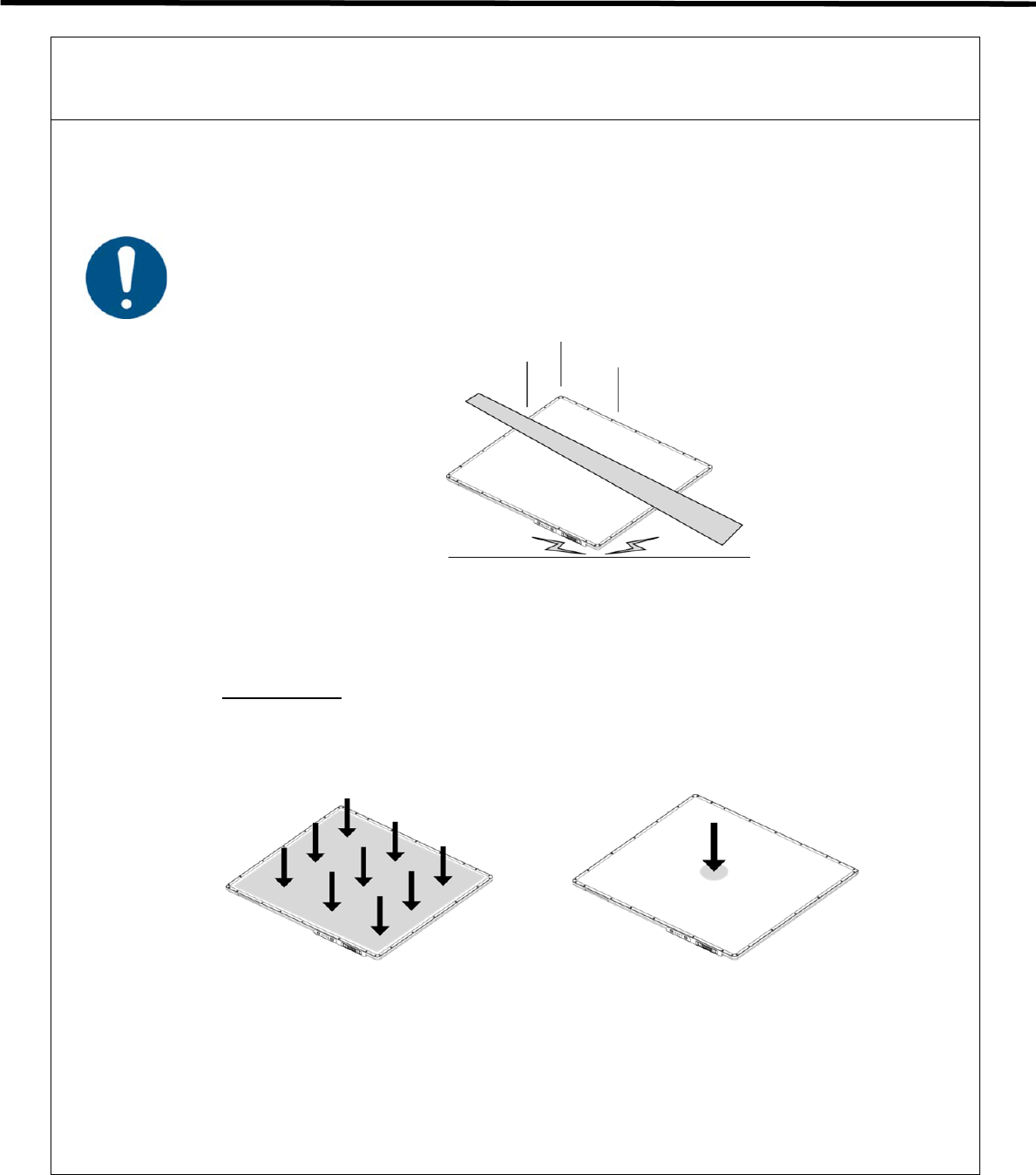
- Do not place excessive weight on the detector.
Otherwise, the internal image sensor may be damaged.
<Load Limit>
- Be sure to use the detector on a flat surface do it will not bend. Otherwise, the
internal image sensor may be damaged. Be sure to securely hold the detector while
using it in upright positions. Otherwise, the detector may fall over, resulting in injury
to the user or patient, or may flip over, resulting in damage to the inner device.
Uniform load: 150 kg over the whole area
of the detector
Local load: 100 kg on an area 40 mm
in dimeter

EVS 3643 User’s Manual
1. Safety information
10-EVS1MADB001 10
1-2. Notes for using the equipment
When using the equipment, take the following precautions. Otherwise, problems may occur and the equipment
may not function correctly
System Diagnostic
The Ecali1 software runs a system diagnostic.
Run Ecali1 software after installing the system and at least once a year. If an error occurs, report the detailed
error information to DRTECH local dealer or distributor
Calibration
To ensure optimal performance of the system, it is important to verify that the system is calibrated.
Before exposure
- Be sure to check the equipment daily and confirm that it works properly.
- Sudden heating the room in clod area will cause condensation to form on the equipment. In this case, wait
until the condensation evaproates before performing an exposure. If the equipment is used while the
condensation formed on it, problems may occur in the quality of captureed image. When an air-conditioner
is used, be sure to raise/lower the temperature gradually so that a difference in temperature in the room and
in the equipment does not occur, to prevent condensation.
During exposure
- Do not use the selected frequency chanel for other wireless device. Mutual interference may affect the
image data transmission rate.
- Do not use the detector near devices generating a strong magnetic field. Doing so may produce image
noise or artifacts.
CAUTION
The owner is responsible for ensuring that the system diagnostic is
performed every year.
Do not try to use the system if the system diagnostic is failed.
CAUTION
The owner is responsible for ensuring that the system calibration is
performed after the system installation is completed or the system is
repaired. Do not try to use the system if system calibration is not performed.

EVS 3643 User’s Manual 1. Safety information
11
Electric Shock Hazards
- To reduce the electric shock hazard, the system must be connected to an electrical ground.
- A three onductor AC power cable is supplied with this system to provide the proper electrical grounding. The
power cable must be plugged into an UL-approved three-contact electrical outlet.
- Do not disassemble or modify the product as it may result in fire or electric shock. There are no operator
serviceable parts or adjustments inside the systems. Only trained and qualified personnel should be
permitted access to the internal parts of the system.
- If an APPLIANCE COUPLER or Mains Plug or other separable plug is used as the isolation means to safety
Disinfection and cleaning
- Wipe it with a dry cloth slightly damed with a neutral detergent.
- Do not use solvents such as alcohol, thinner or benzene. Doing so may damge the surface of the equipment
- Do not clean the system with turning the power on.
Operating/storage environment
- Be sure to use and store this equipment under the conditions described below:.
Temperature Humidity Atmospheric pressure
Operating environment 10 to 35 ℃ 30 to 85 % RH 700 to 1060 hPa
Transport & Storage
environment -15 to 55 ℃ 10 to 90 % RH 500 to 1060 hPa
- Do not expose this equipment to high temperatures and/or high humidity. Malfunction is occur.
- When not in use, keep the detector, handle unit, and grid in a designated location or in a location where
they are safe and cannot fall down.
Notes on disposal
- Disposal of this product in an unlawful manner may have a negative impact on health and on the
environment. When disposing of this product, therefore, be absolutely sure to follow the procedure which is
in conformity with the laws and regulations applicable in your area.
- The expected life span of EVS 3643 system is about 3 years
Handling the equipment
-The equipment must be handle with care to avoid personel injury or damage to the internal image sensor.

EVS 3643 User’s Manual 2. Introduction
12
The EVS 3643 Wireless is advanced wireless digital radiographic equipment in the DRTECH Exprimer series.
This equipment is designed to provide the highest resolution and sensitivity in the series. In addition, the
wireless LAN (IEEE 802.11n*) communication feature improves the operability, and high-speed processing.
2-1. Features
- Wireless LAN communication (IEEE 802.11n*) includes a lightweight and thin detector that is easy to handle.
- The shape of the detector, which is identical to that of a conventional film cassette complying with ISO4090,
enables digital radiography in the existing analog radiography configuration
- The new sensor with 140 μm of pixel pitch and CsI (Cesium Iodide) used for the scintillator produces high
resolution (approx. 7.86 Mega pixels) digital images within the effective imaging area (358 x 430 mm) with
low doses of X-rays
- Depending on the operating conditions at each site, the wiring unit (optional) enables the equipment to be
used through expansion to a wired connection
- At the time of installation, set a specific channel in the frequency band of 5.0 GHz before using the LAN.
Note that the available frequency band for this standard varies, depending on the local radio laws,
regulations and system requirements.
2-2. Intended use
- The EVS 3643 Digital X-ray detector is indicated for digital imaging solution designed for providing general
radiographic diagnosis of human anatomy. This device is intended to replace film or screen based
radiographic systems in all general purpose diagnostic procedures. This device is not intended for
mammography applications
EVS 3643 User’s Manual 2. Introduction
13
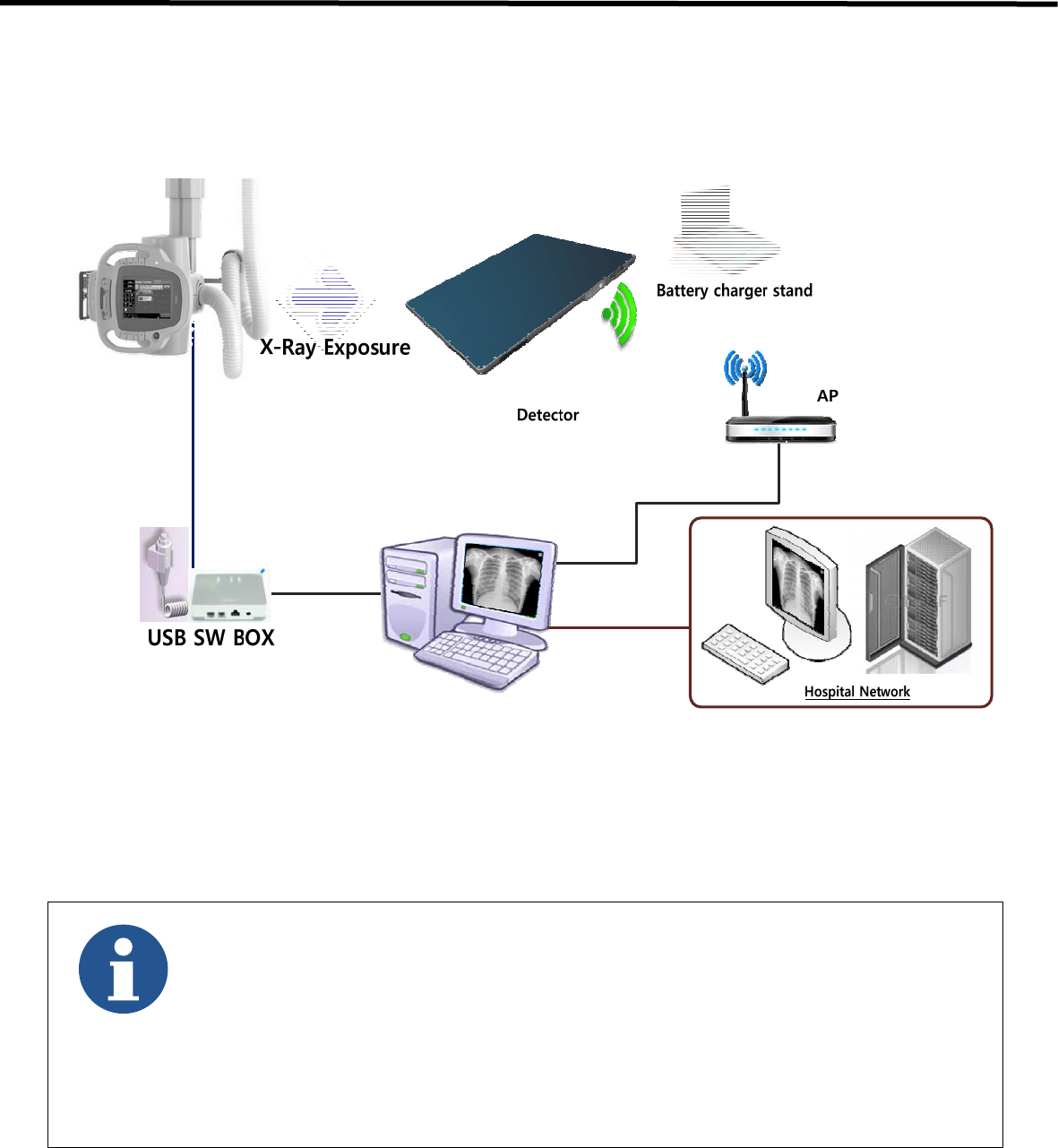
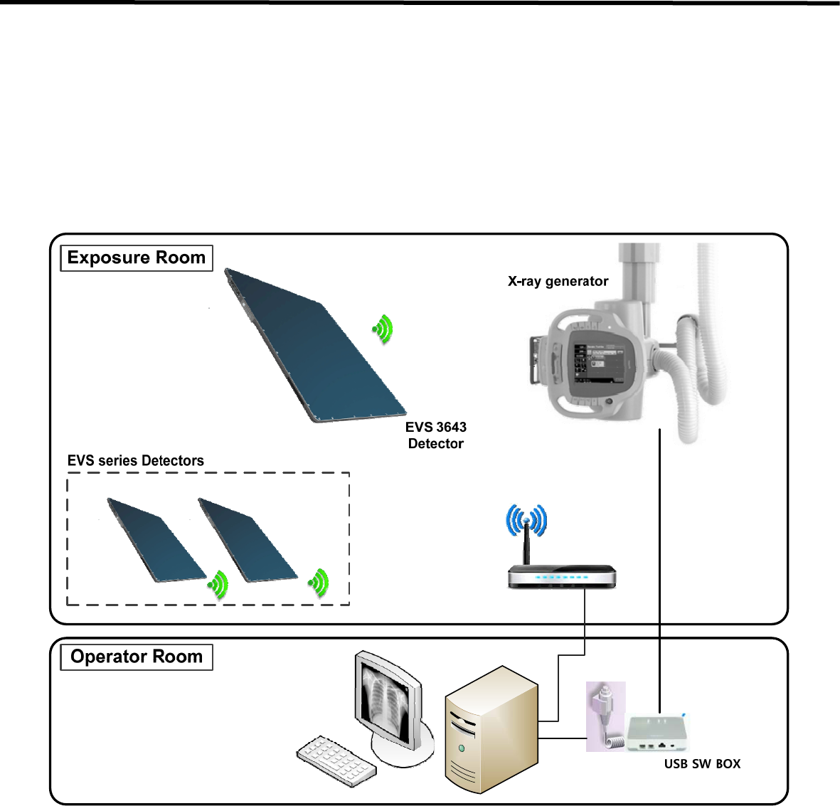
2-3. System Configuration
Generally, the EVS 3643 detector is used in system configuration as illustrated below:
Figure 2.1 EVS 3643 system configuration
Wireless communication is established between the EVS 3643 Wireless detector and System Control Unit. The
EVS-3643 system is compliant with IEEE 802.11a/b/g/n (2.4 ㎓ / 5 ㎓). The available frequency band may vary
depending on local radio laws and system requirements. Consult your local dealer for the frequency available in
your area.
- Use of multiple WLAN devices within the same frequency band may interference with
each wireless communication and cause a decline in transmission speed
- Do not cover or block the wireless module of the detector. Otherwise, the
transmission speed or operable distance may be reduced.
- Recommended maximum operating distance of wireless communication between the
detector and system synchronization unit is 8 meters.
EVS 3643 User’s Manual 3. Product description
14
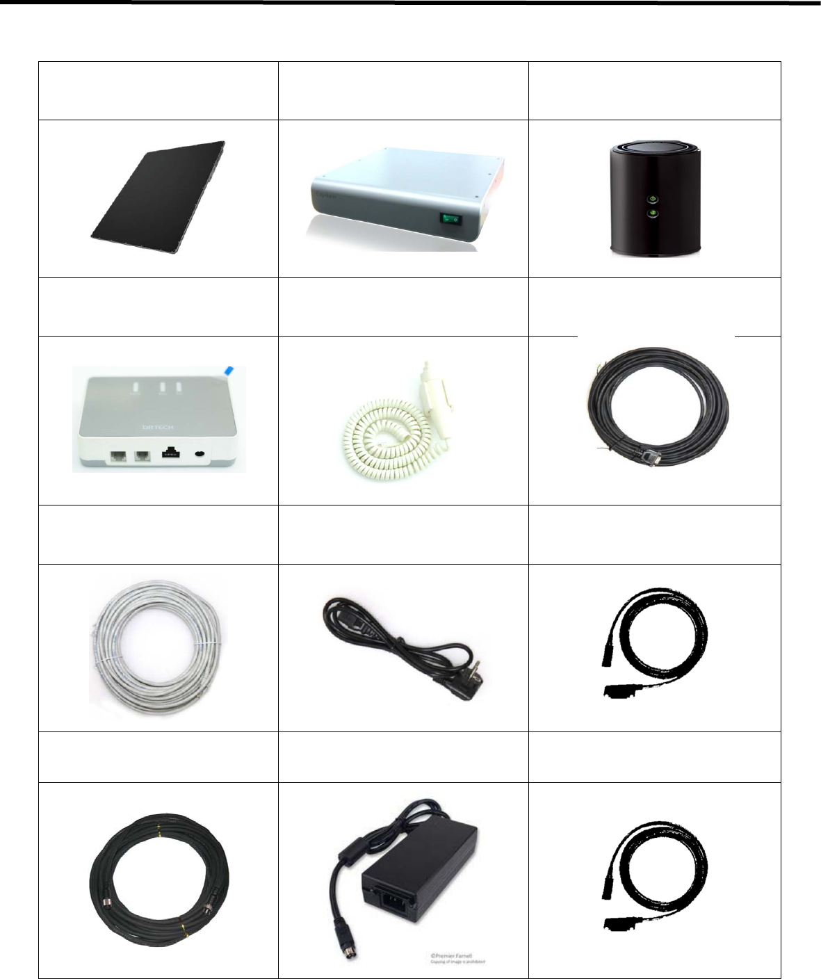
EVS 3643 Wireless system consists of detector, system synchronization unit (SSU), CDs and relevant
accessories. (Refer to chapter 3-1 “Product Components” for CD information)
X-ray Detector (EVS 3643) System Syncronize Unit
(EVS-SSU01) Option
Access Point
(D-Link DIR-850L)
USB Switch Box Hand Switch
Generator Interface Cable
(15m) Option
LAN Cable
(Gigabit LAN 10 m)
AC Power Cable (2m) Option Tether Interface (3 m)
Interface Cable(7 m), Option Power adaptor (12V, 7.08A) Adaptor cable (3 m) Option
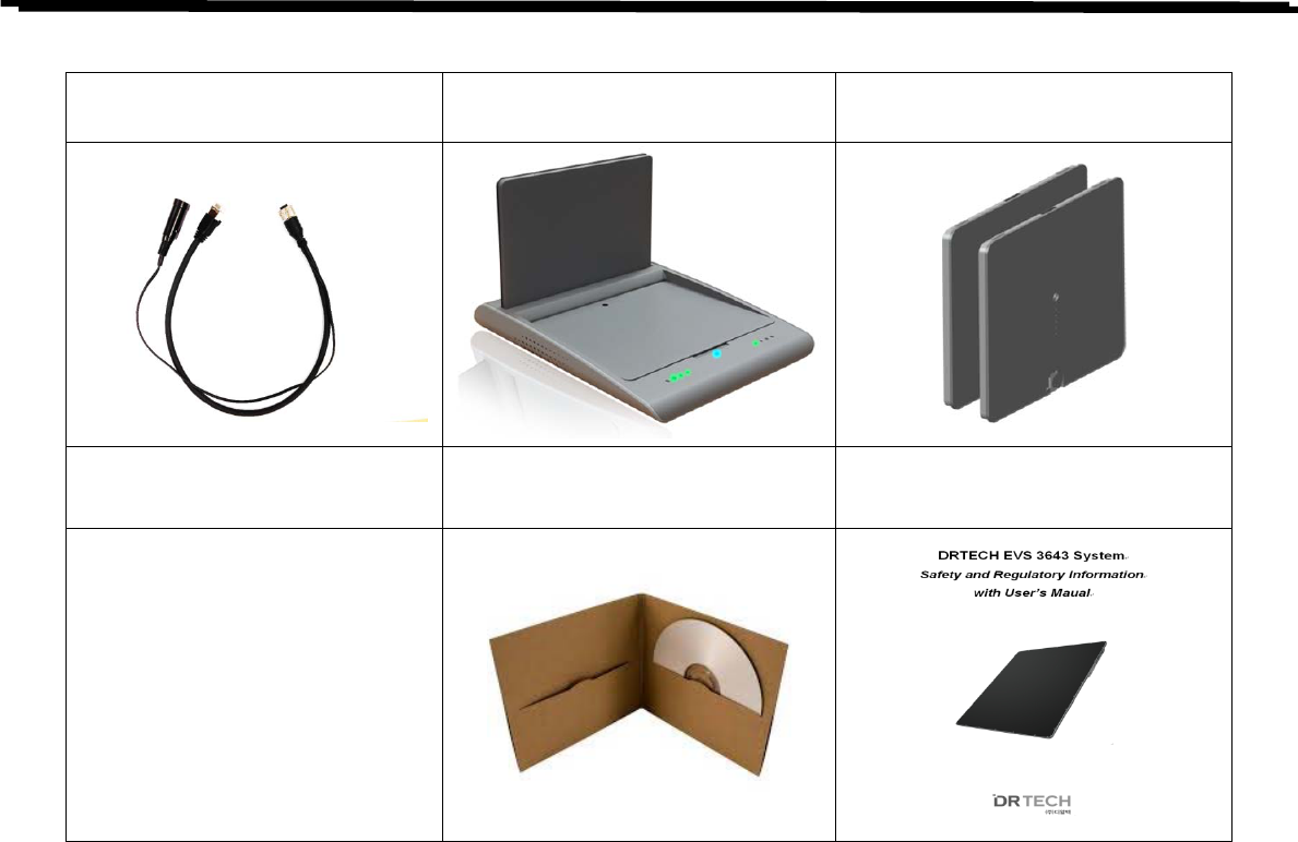
EVS 3643 User’s Manual
3. Product description
10-EVS1MADB001 15
Functional cable (0.5 m) Battery charger
(EVS-BCS)
Battery pack
(EVS-MBP)
CD(Software / Calibration) Maual (Hard Copy)
Table 3.1 EVS 3643 packaging

EVS 3643 User’s Manual
3. Product description
16
3-1. Product component
Item Product name
Flat panel detector EVS 3643(Scintillator: CsI : Tl) 2.98 kg
System syncronization unit (SSU) EVS-SSU01 : 2.2 kg Optional
Battery chaarger and Battery pack EVS-BCS (charger): 0.5 kg
EVS-MBP (battery pack): 0.24 kg
CD (Software / Calibration)
Document: User ‘s Manual (PDF)
Calibration Data: Defect Map, Gain, Post Offset, Pre Offset
Calibration & Configuration S/W: ECali1
User’s Maual Hard Copy
Accessories
AC Power Cable (2m)
Generator Interface Cable (15m, Optional)
USB Switch Box
Hand switch
LAN Cable (10m, Direct, 1000BASE-T)
Tether Cable (3m, Optional)
Adaptor cable (3m, Optional)
Functional cable (0.5 m)
Power adapter
Interface Cable (7m, Optional)
License Dongle Key (USB)
Table 3.2 Product componets
WARNING
The use of accessories and cables other than those specified, with the exception of EVS 3643 Wireless
accessories and cables sold by DRTECH Co., LTD. as replacement parts for internal components, may result in
increased emissions or decreased immunity of the equipment. Accessory equipment connected to the analog
and digital interfaces must be certified according to the respective IEC standards. All combinations of equipment
must be in compliance with IEC 60601-1-1 system requirements. Any person who connects additional
equipment to the signal input or signal output ports configures a medical system, and is therefore responsible for
ensuring that the system complies with the requirements of the system standard IEC 60601-1. If in doubt,
consult DRTECH technical support representative.

EVS 3643 User’s Manual 3. Product description
17
Workstation (Recommended and minimum but NOT included)
Item Specification
Operating system Windows 7 64 bit SP1 (Professional Edition or higher)
CPU Intel Core i5 2600 or higher (or compatible CPU)
Memory 4GB or higher
Hard disk 1TB or higher
LAN card
Gigabit (Detector only)
Intel® PRO 1000 Series (Gigabit LAN Card for network interface)
Min. Requirements: 1Gbps,
Jumbo Frames: 9K
Receive Descriptors: 2K (higher than 1024)
This is not dedicated to DICOM
Monitor 1024 x 768 or higher
Optional disc drive CD or DVD R/W
Table 3.3 Workstation
Grid (Recommended but Not included)
Item Description
SID 100 / 130 / 150 / 180 cm
Ratio 8 : 1
Frequency 215 Line/inch
Inter spacer Al
Table 3.4 Grid specifications
3-2. X-ray Imaging condition
X-ray Energy Range
40kVp ~ 150kVp
Reliability (Lifetime Dose)
More than 74Gy (35uGy x 365days x 24hours x 60minutes x 60seconds/15sec)

EVS 3643 User’s Manual 4. Part name and function
18
4-1. Detector specification
Item Description
Model EVS 3643
Purpose General Radiography
Pixel Pitch 140 um
Scintillator CsI (Cesium Iodide)
Image Matrix Size 2560 × 3072 pixels
Effective Imaging Area (H x V) 358 x 430 mm
Image Acquisition and Transfer Time < 3 sec.
Spatial Resolution Min. 3.5 line pair/㎜
Rated Power Supply
Wireless
Wired
DC +12V 2 A
Powered by the battery pack (4,000 mA h)
Powered by SSU using tether interface
Powered by Power adopter using tether interface
Power Consumption Max. 24 W
Network Interface 14 bit Digital Output Ethernet (1000BASE-T)
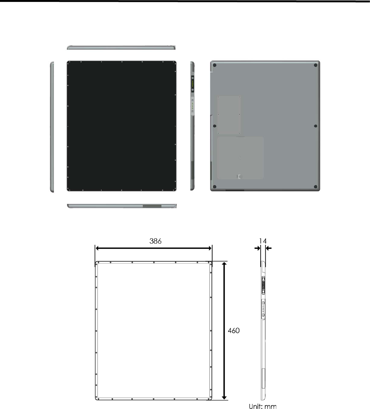
Dimensions (㎜) 386 (H) × 460 (V) × 14 (D)
Weight 2.98 kg
Environmental Requirements
Operation
Temperature: +10 ~ +35℃
Humidity: 30 ∼ 85% RH(Without Condensing)
Atmospheric pressure: 700 ∼ 1060 hPa
Storage and Transportation(unpacked)
Temperature: -15 ~ +55℃
Humidity: 10 ∼ 90% (Without Condensing)
Atmospheric pressure: 500 ∼ 1060 hPa
Table 4.1 Detector specifications
†Tether Interface: Allows the detector to communicate with SSU via Ethernet cabling when wireless
communications is not available or higher speed data transfer is necessary
EVS 3643 User’s Manual
4. Part name and function
19
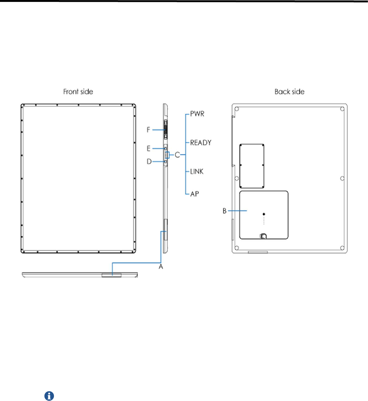
4-2. Detector component
The detector is designed to capture radiographic images.
Captured images are transmitted to the EVS 3643 image-capture computer using the wireless/wired data
transfer
Figure 4.1 Detector components
A. Wireless antena :Transmits image data with wireless comunication (IEEE802.11n).
B. Battery Pack : Supplies electricla power to the detector while communication wirelessly
C. Sataus indicators
AP: Alter button for Wireled/Wireless(2.4 GHz / 5 Hz)
Link: Shows detector registraion and connection status.
Ready:shows data comunication status
Power: Shows power on/off status of the detector.
Simultaneous blinking of two or more LED lamps indicates a system error.
D. AP Button: registration detector.
E. Power Button: Detector power on / off
F. Connecter: Data communication and power supplying thought tether cable
EVS 3643 User’s Manual
4. Part name and function
20
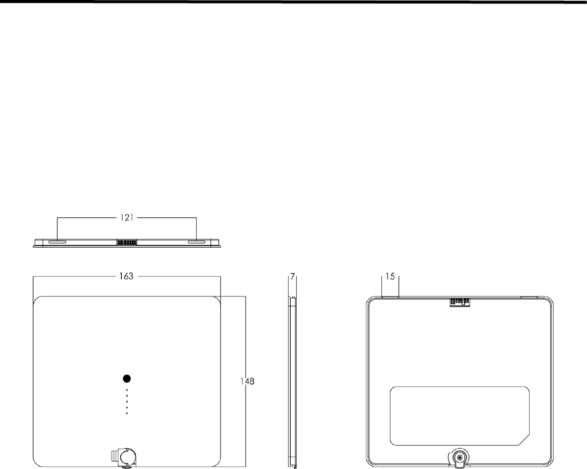
4-3. Detector dimension
Figure 4.2 Detector dimension

EVS 3643 User’s Manual 4. Part name and function
21
4-4. Power supply and SSU (System syncronization unit)
4-4-1 SSU Specifications
Item
Description
SSU
(System synchronization unit)
Model EVS-SSU01
Power Supply Input: AC100 to 240V, 50/60㎐ Output: DC +12V 8.3A, 75W
Dimensions (W x H x D) 260 mm x 248 mm x 49 mm
Weight 2.2 kg
Environmental Requirements
Operation
Temperature: +10 ~ +35℃
Humidity: 30 ∼ 85% RH(Without Condensing)
Atmospheric pressure: 700 ∼ 1060 hPa
Altitude: Max. 2 km
Storage and
Transportation(unpacked)
Temperature: -15 ~ +55℃
Humidity: 10 ∼ 90% (Without Condensing)
Atmospheric pressure: 500 ∼ 1060 hPa
Altitude: Max. 2 km
Table 4.2 System syncronization unit specifications
EVS3643 User’s Manual 4. Part name and function
4-5. Battery Charger and Battery Pack
4-5-1 Battery Charger
Item Description
Model EVS-BCS
Simultaneous Charging Battery Pack 2 EA
Charging Time 3 hours
Rated Power Supply DC +12 V, 6 A Max.
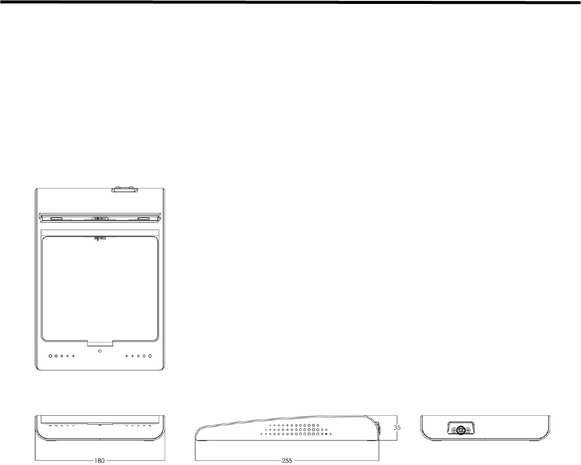
Dimensions (W x H x D) 180 mm x 255 mm x 35 mm
Weight 0.5 kg
Table 4.3 Battery charger specifications
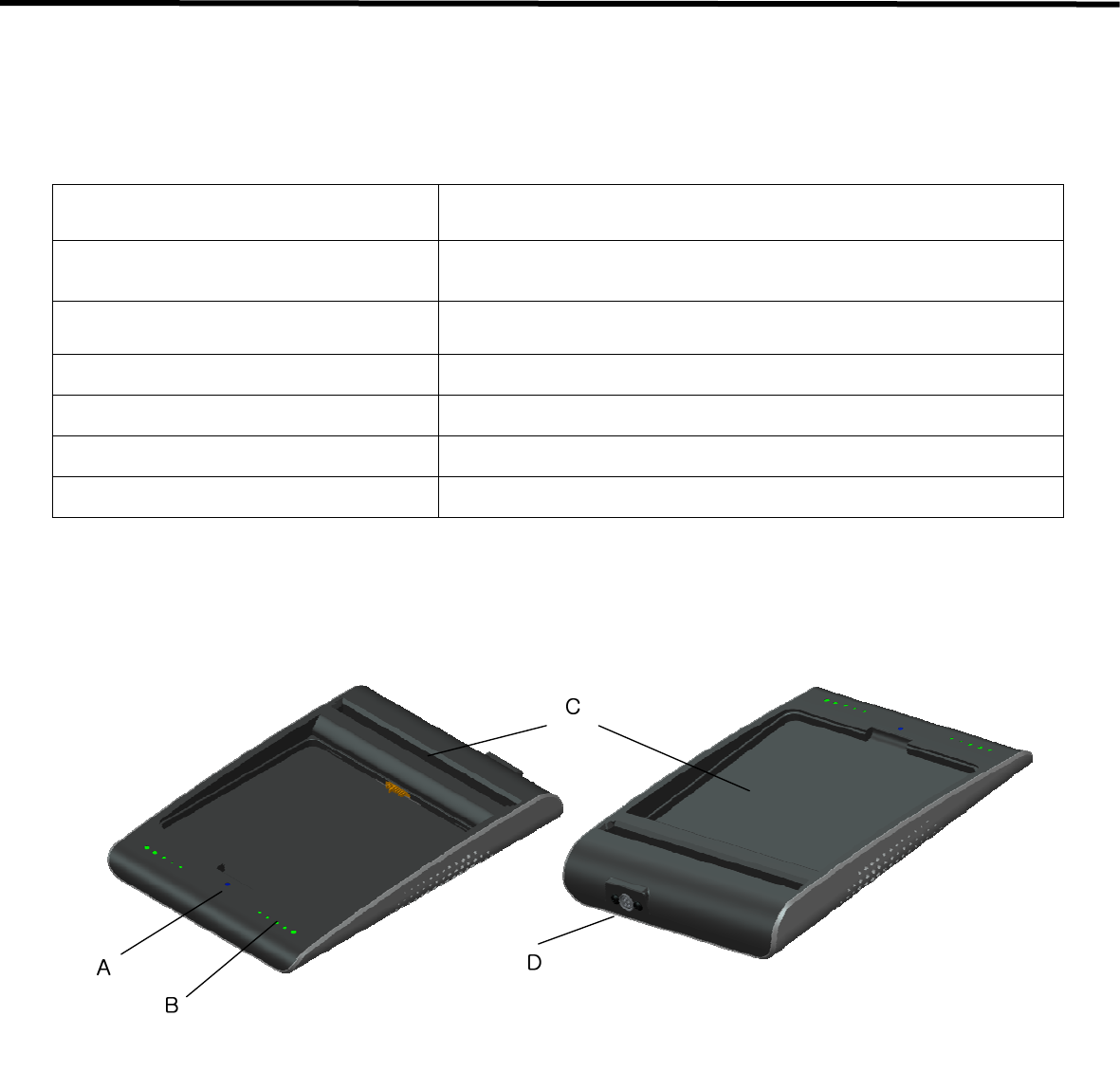
4-5-1-1 Battery charger components
Figure 4.4 Battery charger
A. Power indicator : indicates the power on/off status..
B. Charging indicator : Indicates the charging status.
C. Battery compartment:
Insert the battery pack to charge.
D. DC Input : Connect the DC adapter to supply electrical power to the battery charger
EVS 3643User’s Manual
5. Operating procedure
4-5-1-2 Battery charger dimension
Unit : mm
Figure 4.4 Battery charger system

EVS 3643 User’s Manual 4. Part name and function
RA-EVS-UM-100
4-5-2 Battery Pack specification
Item Description
Model EVS-MBP
Cell Type Lithium Polymer
Number of Cell 2S1P (2series 1 Parallel)
Rated Power Supply Output : DC +7.4 V
Life Approx. 500 times (charge / discharge 1 cycle)
Dimensions (W x H x D) 163 mm x 148 mm x 7 mm
Weight 0.24 kg
Table 4.5 Battery charger specifications
4-5-2-1 Battery charger components
Figure 4.5 Battery pack
A. Charging indicator : Indicates the charging status
B. Latch knob : rotating on /off for battery swap
EVS3643 User’s Manual
4. Part name and function
4-5-1-2 Battery pack dimension
Unit : mm
Figure 4.6 Battery pack dimension

EVS 3643User’s Manual
5. Operating procedure
4-5-3 Charging Battery Pack
The battery pack supplies power to the detector during wireless connection.
Be sure to use only the dedicated battery pack and fully charge it before use.
Connect the power adapter to the DC Input port of the battery charger. the power LED lights in blue indicating
the presence of direct current (DC) power.
Insert the battery pack into the battery charger. Charging starts automatically. The charge LED lights green
when the battery pack is being charged. After the battery pack is charged completely, all level of the charge
LED will going to luminance
Gently pull the charged battery pack to remove from the battery charger
WARNING
Securely plug the power cord into the power source. If contact failure
occurs, or if dust or metal objects come into contact with the exposed
metal prongs of the plug, fire or electrical shock may occur
CAUTION Be sure to stop charging the battery pack when the charge LED lights in
green beyond the specified charging time. Not doing so may result in
battery pack overheating or smoking or in explosion or fire.
CAUTION You must use the power adaptor that is certified with IEC 60950 or IEC
60601-1.
Two batteries can be charged at the same time.
It takes approximately two hours to fully charge a battery pack. The
required charging time may vary depending on the temperature and
remaining battery level.

EVS 3643 User’s Manual
4. Part name and function
RA-EVS-UM-100
4-6 Wireless access point(Optional)
This antenna equipment relays captured images from the detector to the control system. No operation is
required for this equipment while using the EVS Digital Radiography system.
4-5-1 Access point Specifications
Item
Description
Access Point
(AP)
Model D-Link DIR-850L
Power DC 12V/2A
Communications IEEE 802. 11n/g(2.4 GHz), IEEE 802.11ac/n/a (5GHz)
Dimensions (W x H x D) 85.73 x 111.13 x 145.28 mm
Weight 0.28 kg
Environmental Requirements
Operation
Temperature: 0 ~ +40 ℃
Humidity: 10 ∼ 90% RH(Without Condensing)
CAUTION Do not use the wireless access point within the patient’s vicinity

EVS 3643User’s Manual 5. Operating procedure
The EVS 3643 Detector is properly adjusted at installation by the service engineer. If you encounter any
problems during normal operation or daily inspections, consult your sales representative or local DRTECH
dealer.
General workflow
The following workflow indicates the procedures after startup of the EConsole1 and other system
equipment
5-1. Preparing to use the detector
5-2. Operating the detector
Attach a fully-charged battery pack to the detector.
2. Resister1) the detector and make connection2) to the
EConsole1 power supply to the detector
1) : A procedure in order to register the detector
to a specific digital radiography system
2) : Network connection between the EVS 3643
wireless detector and the EConsole1
3. Conduct Examination
3) :Selection of EVS 3643 wireless
from the Exprimer series detector
Selection of wireless/wired
data transfer
Select or resister the patient information
Select the protocol (selection3) of the detector)
- Arrange the patient in the correct posture
- Position the X-ray generator to adjust the
exposure field
- Check all the conditions
Check the captured images
List the images
Transmit the images
Sterilize the portion of the detector that
has been in contact with a patient
5-3. Ending use of the detector
1. Turn off the detector
Conduct the next examination
Loop back procedure
for each body part
Loop back procedure
for each patient
For details, refer to the
operation manual or
setup guide of the
EConsole1
2. Remove the battery pack
1. Turn on the detector
EVS3643 User’s Manual
5. Operating procedure
10-EVS1MADB001 2924
5-1. Preparing to use the detector
CAUTION Be sure to use only the dedicated power supply for the EVS-3643 detector
Standard Configuration
Configuring with SSU (power supply) to the detector
Make sure that the cable is placed to the connector (detector side)
Figure 5.1 EVS 3643 System Configuration
5-2. Operating detector
1
Turn on the detector
Before operating the detector, start up the EConsole1
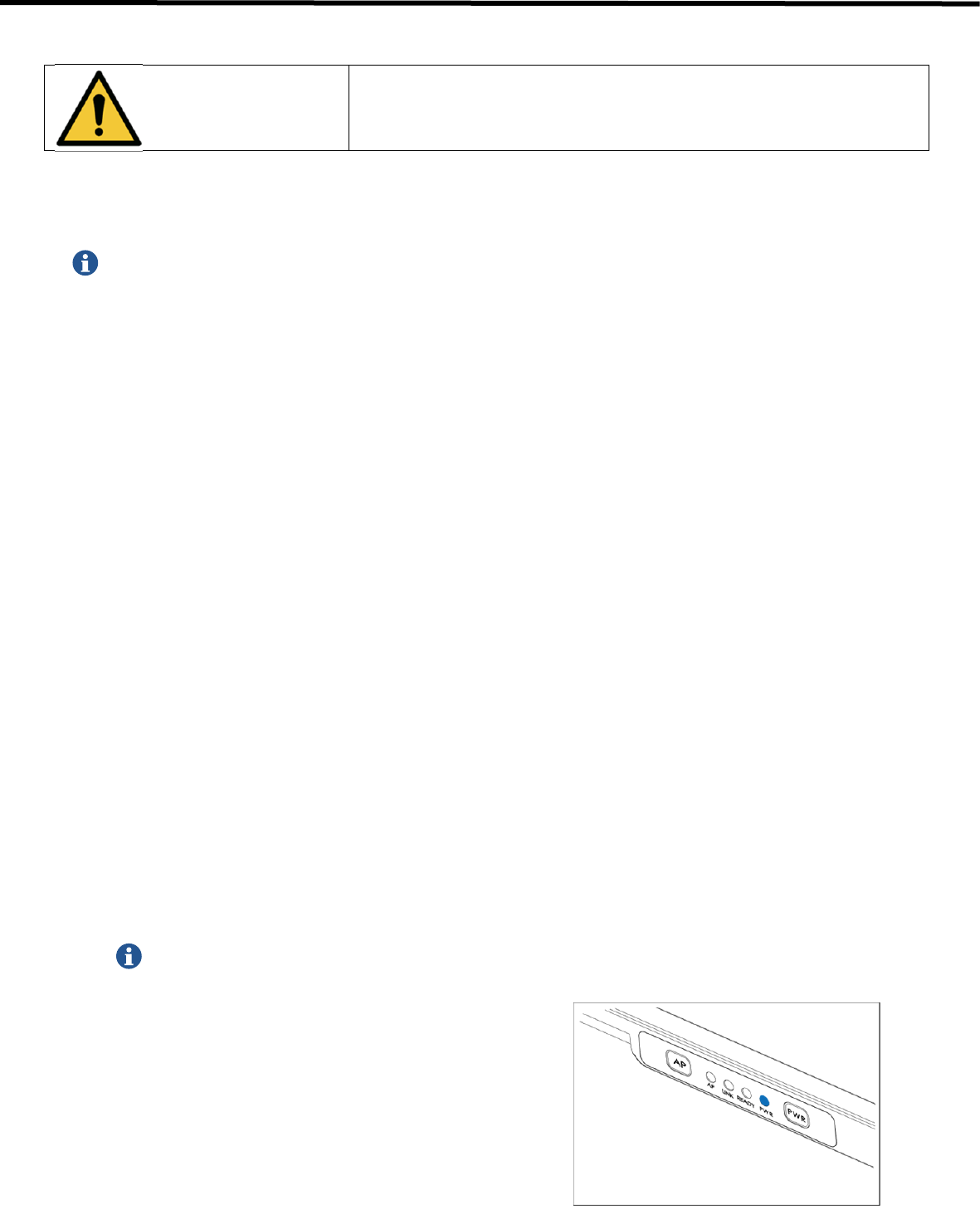
Press and hold the POWER button
(approx. 1 second)
Power lamp(Blue) light up
EVS 3643User’s Manual
5. Operating procedure
2
Register the detector and make connection to the EVS control system
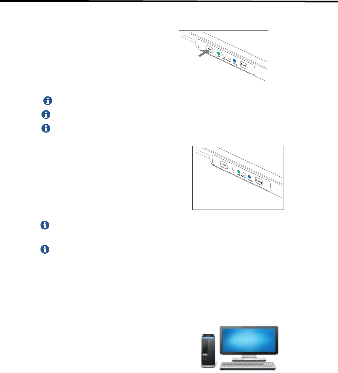
Registration
Press and realease the AP button
Link lamp flashes.
When the AP Lamp flashes 1 time in 2sec, wired mode status has showing.
When the AP Lamp flashes 2 times in 2sec, wireless (2.4 GHz) mode status has showing.
When the AP Lamp flashes 3 times in 2sec, wireless (5 GHz) mode status has showing.
Connection
Network connection between the internal
wireless module of the detector and the
wireless access point/EVS control
system is secured automatically
The link lamp lights up when the detector
is resistered and the communication
connection is established
The LINK lamp does not light up when the detector is not registered or the communication
connection is not established.
When the Ready and LINK Lamp flash, a communication error has occurred.
See Troubleshooting.
3
Conduct examination
For details about operation, refer to the Operation Manual for the ECali1.
i) Select the patient information or protocols on the
screen and start the examination.
EVS 3643 User’s Manual
5. Operating procedure
10-EVS1MADB001 25
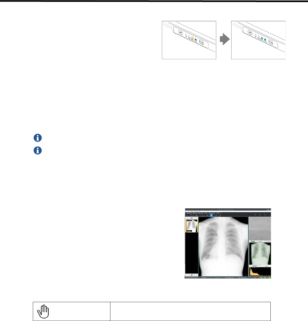
The READY lamp flashes during preparation
for examinations.
The READY lamp lights up when the
detector and EConsole1 change to
exposure ready status.
• Arrange the patient in the correct posture and position the detector aligning it with the target body part.
• Position the X-ray generator to adjust the exposure field.
• Check all conditions before exposure.
Make sure that four LED lamps (POWER, READY, LINK, AP) are lit. This means that the system is
ready to start an examination
A communication error has occurred when two or more lamps flash.
When the READY lamp (green color) flashes slowly, the detector is in detector selection status
(Sleep).
The detector enters detector selection status automatically when it has not been used for a certain
period of time.
ii) Press the exposure switch of the X-ray generator.
Images captured with the detector are transmitted to
the EConsole1 and appear on the monitor.
• Check the images on the monitor.
• If any uncompleted protocols remain, repeat the
procedure ii).
ii) Click the button for ending the examination
images are stored automatically
• To conduct examination for another patient, repeat the step 3.
IMPORTANT
Sterilize the portion of the detector that has been in contact
with a patient to prevent infection

EVS 3643 User’s Manual
5. Operating procedure
10-EVS1MADB001 26
A signal strength indicator appears on the screen of the ECali1 computer. It shows the wireless
communication level between the detector and the ECali1.
Keep the wireless communication level stable on capturing or transmitting images.
Display Signal strengt
(comunication stability) Status Required actions
Very high (Stable) Normal -
High (Stable) Normal -
Low
(Unstable)
Unstable
comunication.
Comunication
speed is
lowered
Check whether there is any obtacle
(e.q., your hands)between the wireless module and
the wireless acess point.
If there is any obtacle, remove it.
If the problem cannot be resolved.
Consult your sales representative or local DRTECH
dealer
No signal
(Comunication failed)
Cannot
comuncations
Confirm that detector and the
access point are turned on.
If the problem cannot be resolved.
Conult your sales representative or local DRTECH
dealer

EVS 3643 User’s Manual 5. Operating procedure
10-EVS1MADB001 27
5-3. Ending use of the detector
Turn off the detector
Press the SSU POWER button.
All the LED lamps are off.
Detector status list
Lamp type Power
Lamp
Ready
Lamp
Link
Lamp
AP
Lamp
Color ■ Blue ■ Green ■ Orange ■ Green ■ Green
Power ON ○ х х х х
During detector registration ○ х ☆ ☆ ☆
Detector registration completed (1 Sec,) ○ ○ ☆○ ☆
Communication established ○ х ○ ☆
During exposure preparation ○ х ☆○ ☆
Ready status or performing an
examination (Ready) ○ ○ - ○ ☆
Detector selection status (Sleep) ○ ★ - ○ -
During image data transmission ○ ○ / ★ - ★ -
Power OFF х х - х -
○ : Light on ☆ : Flashes (On/Off status changes every second)
х : Lights off ★ : Flashes slowly (On/Off status changes every 2 seconds)
- : Unspecified status
EVS 3643 User’s Manual 6. Extension facility
10-EVS1MADB001 28
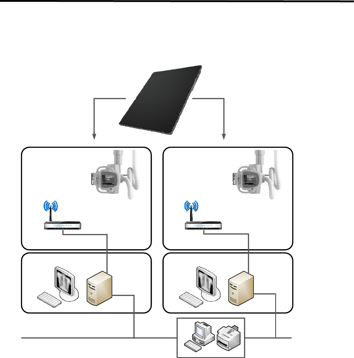
6-1. Using the wireless detector with other EVS series detectors in a
same system
The ECali1 with the EVS 3643 detector enables connection with EXPRIMER series detectors other than
that EVS 3643 detector, according to preset settings. Select a detector when conducting an examination.
For details, consult your sales representative or local DRTECH dealer.
Figure 6.1 Detector dimension
EVS 3643 User’s Manual 6. Extension facility
10-EVS1MADB001 29
6-2. Sharing the detector among different systems
The EVS 3643 detector can be used in two or more systems in which protocols for the detector have
already been preset. For details, consult your sales representative or local DRTECH dealer
EVS 3643 Detector
Hospital Network
X-ray
generator
X-ray
generator
Figure 6.2 Sharing the detector among different systems
EVS 3643 User’s Manual 6. Extension facility
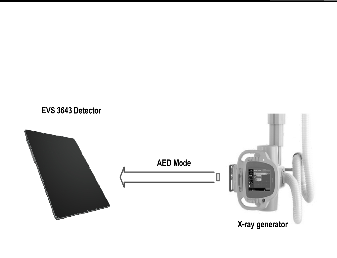
10-EVS1MADB001 30
6-3. AED mode
• AED mode can make exposure as using internal storage in the detector with out a wireless connection
• The images can be transmitted to a PC and used by connecting the detector to Viewer. The transmitting
images in the detector are removed automatically.
• Image processing and correction are available after connecting the detector to Viewer
Figure 6.3 AED mode
EVS 3643 User’s 6. Extension facility
10-EVS1MADB001 31
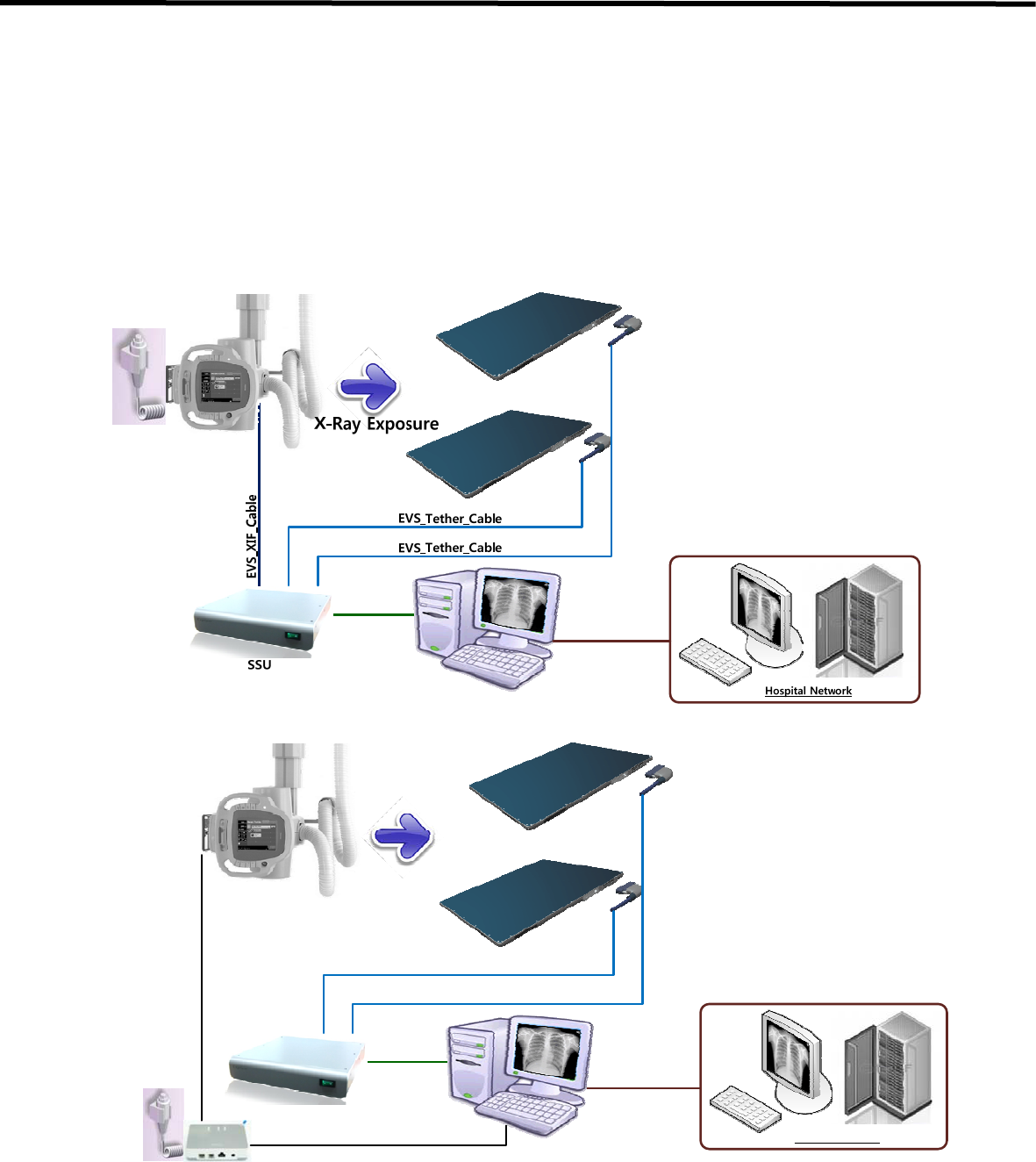
6-4. Wiring connections
The EVS 3643 detector has a cable connector. With the wiring unit (optional), it is possible to expand from
a wireless configuration to a wired configuration (see the figure below). Wired configuration is suitable for
use where the detector is set in a Bucky stand and table in place of a film cassette. In this configuration, for
the reason that data communication and power supply are made via a cable, users do not have to be
concerned about power and wireless communication failure. This reduces the time and labor involved in
charging and replacing.
Figure 6.4 Wiring connection with SSU
SSU
Hospital Network
EVS_Tether_Cable
EVS_Tether_Cable
X-Ray Exposure
USB SW BOX
X-ray Generator
Figure 6.5 Wiring connection with USB S/W BOX
For details about wired configuration, consult your sales representative or local DRTECH dealer.
EVS 3643User’s Manual
5. Operating procedure
10-EVS1MADB001 32
7-1. Hardware Installation
This section describes how to connect the EVS 3643 system (Detector)
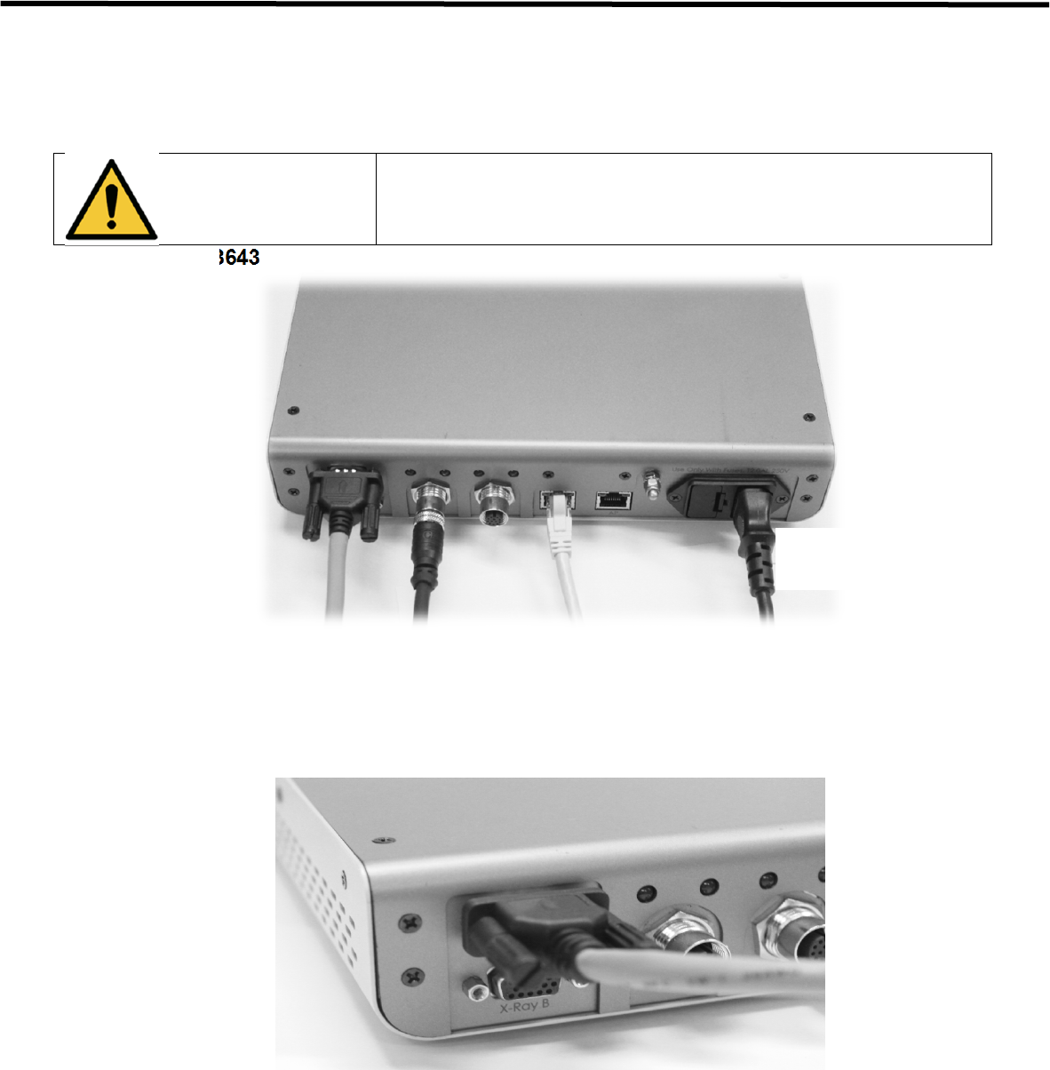
7-1-1 EVS 3643
1 Connect the one end of the generator interface cable to the X-ray port of SSU, and the other to the port of
the x-ray generator.
CAUTION Installation of this equipment should be made by licensed and authorized
personnel.
wiring
connection
EVS 3643 User’s
7. How to Install
10-EVS1MADB001 33
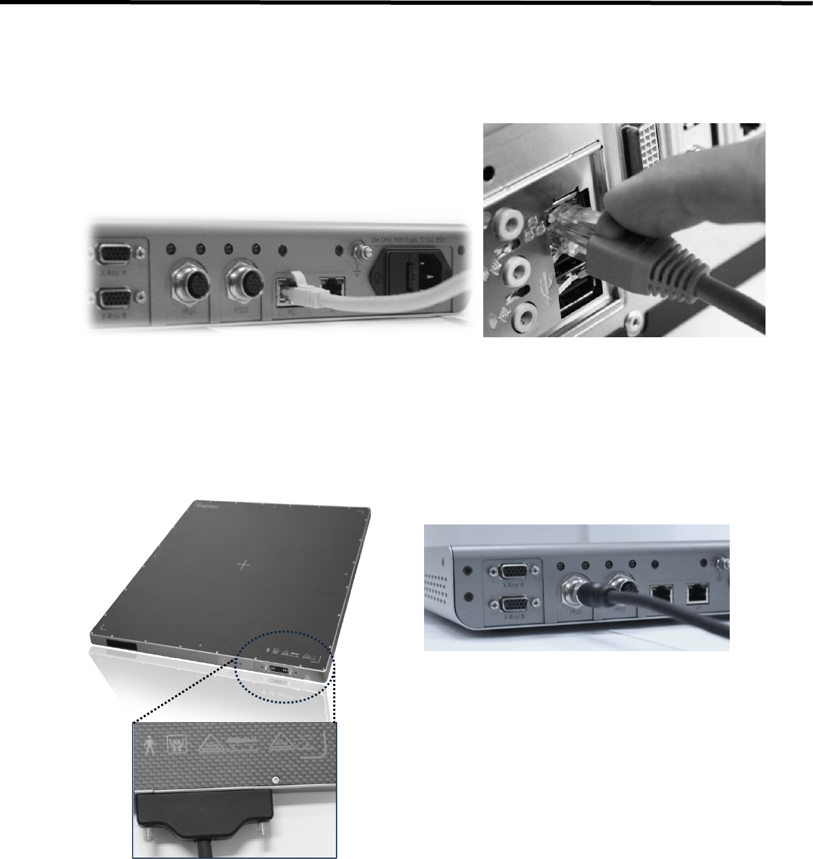
2 Connect the LAN cable to PC port of SSU, and the other to the LAN Card connector of workstation
assigned for the data transfer
3 To transmit image data and connect power with Tether Interface, connect the Tether interface cable to FPD
1 or FPD 2 of SSU
Tether
EVS 3643 User’s
7. How to Install
10-EVS1MADB001 34
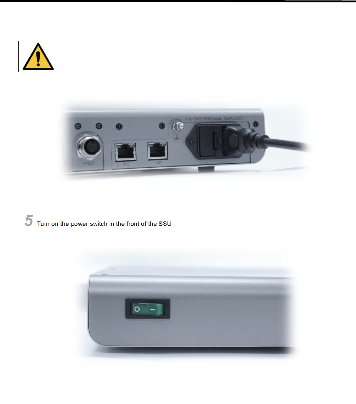
4 Connect the power cable to the AC pport of the SSU to supply power
5 Turn on the power switch in the front of the SSU
CAUTION This equipment must only be connected to a main power with protective
earth

EVS 3643 User’s
7. How to Install
10-EVS1MADB001 35
7-2. ECali1 Installation
7-2-1 System Requirements
Table 7.1. System requirement
Items Minimum Recommended
CPU Intel i3-2100 Intel i5-3470
RAM 2 GB 4 GB
HDD 100 GB 500 GB
VGA Intel HD GRAPHIC 2000
NVIDIA GeForce
GT630 1GB
ODD CD-ROM DVD Recorder
OS Windows XP Pro SP2 Windows 7 Pro
32 / 64bit
Display Size 17 inch 23 inch
Display Resolution 1024 x 768 1920 x 1080
√ Efficient operation is not guaranteed for PCs that do not comply with the recommended specification.
7-2-2 Installation & Removal
Installation prerequisites
Windows 7
Windows 7 users must set the User Account Control (herein after ‘UAC’) permission and disable the
firewall.
1) UAC Setting
① Click the start icon
② Click ‘Control Panel’
③ Select ‘User Accounts’
④ In the User Accounts window, click ‘User Accounts’
⑤ In the User Accounts task window, click ‘Change User Account Control Setting’
⑥ Adjust the slider to the ‘Never notify,’ and then click ‘OK’.

EVS 3643 User’s Manual
7. How to Install
10-EVS1MADB001 36
2) Disabling the Firewall
① Click the Start icon
② Click ‘Control Panel’
③ Click ‘Security’
④ Click ‘Windows Firewall’
⑤ Click ‘Turns Windows Firewall on or off’ on the left
⑥ Click ‘Off (not recommended),‘ and then click ‘OK’
Windows 8
Windows 8 users must set the User Account Control (herein after ‘UAC’) permission,
Disable the firewall and run the program as the system administrator.
3) UAC Setting
① Click ‘Setting’ on the right hand menu
② Click ‘Control Panel’
③ Select ‘User Accounts’
④ In the User Accounts window, click ‘User Accounts’
⑤ In the User Accounts task window, click ‘Change User Account Control Setting’
⑥ Adjust the slider to the ‘Never notify,’ and then click ‘OK’
4) Disabling the Firewall
① Click ‘Setting’ on the right hand menu
② Click ‘Control Panel’
③ Click ‘Security’
④ Click ‘Windows Firewall’
⑤ Click ‘Turns Windows Firewall on or off’ on the left
⑥ Click ‘Off (not recommended),‘ and then click ‘OK’
5) Run as Administrator
Windows 8 users must run the Installation File and Program as the Administrator
Install the program by right clicking (press and hold, if touch screen) and
selecting ‘Run as Administrator’
After completing the installation, set the icon, so that it always runs as administrator
EVS 3643 User’s Manual 7. How to Install
10-EVS1MADB001 37
① Right click (press and hold, if touch screen) the shortcut icon
② Click ‘Properties’
③ Click the ‘Advanced’ icon in the ‘Shortcut’ tab‘
④ Check the ‘Run as administrator’ box, click on ‘OK’
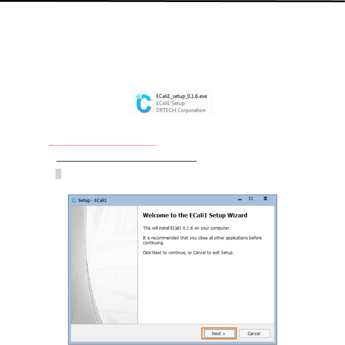
7-1-3. Installation
Run the provided setup file.
Figure7.1. ECali1 Setup File
√ At least 2GB of available HDD space is required for the proper installation of ECali1!
√ Windows 8 users must run the file as ‘administrator’.
→Right-click the file, select ‘Run as administrator’ in the menu.
Figure 7.2. Setup Wizard Window
EVS 3643 User’s Manual 7. How to Install
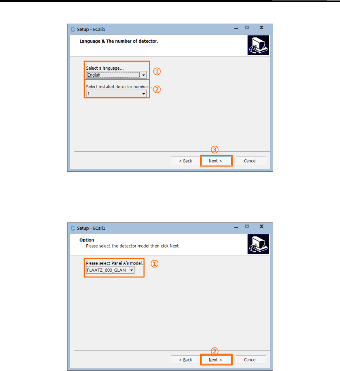
10-EVS1MADB001 38
Figure7.3. ① Language & ② Number of Detector Setting
Figure7.4. Setting of the Model of the First Detector
EVS 3643 User’s Manual 7. How to Install
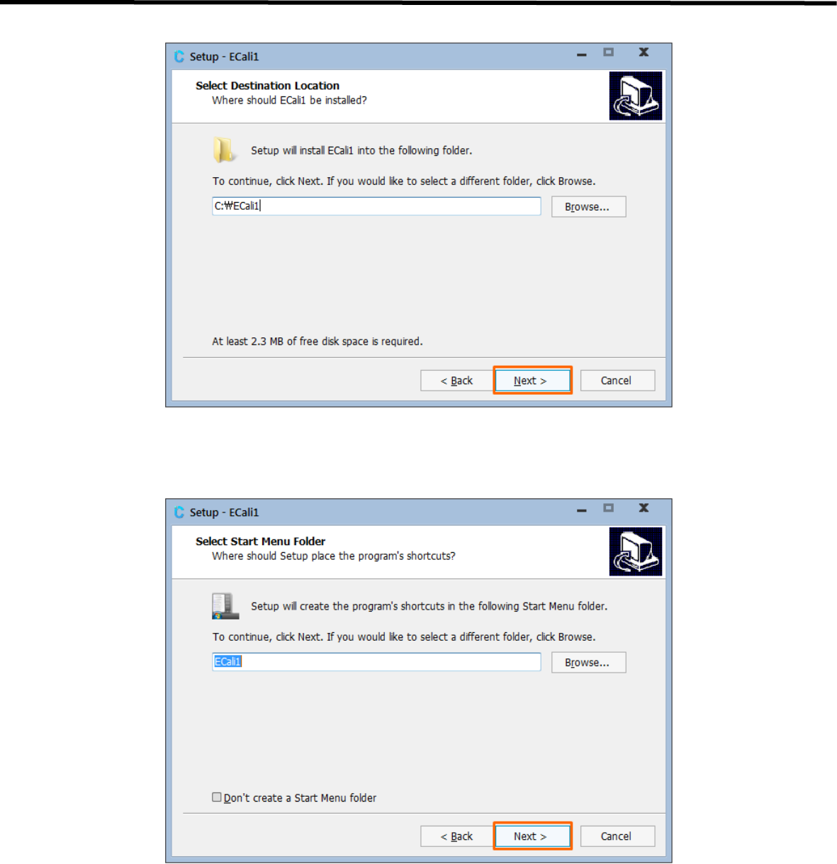
10-EVS1MADB001 39
Figure7.5. Installation Path Setting
Figure 7.6. Start Menu Folder Selection
EVS 3643 User’s Manual 7. How to Install
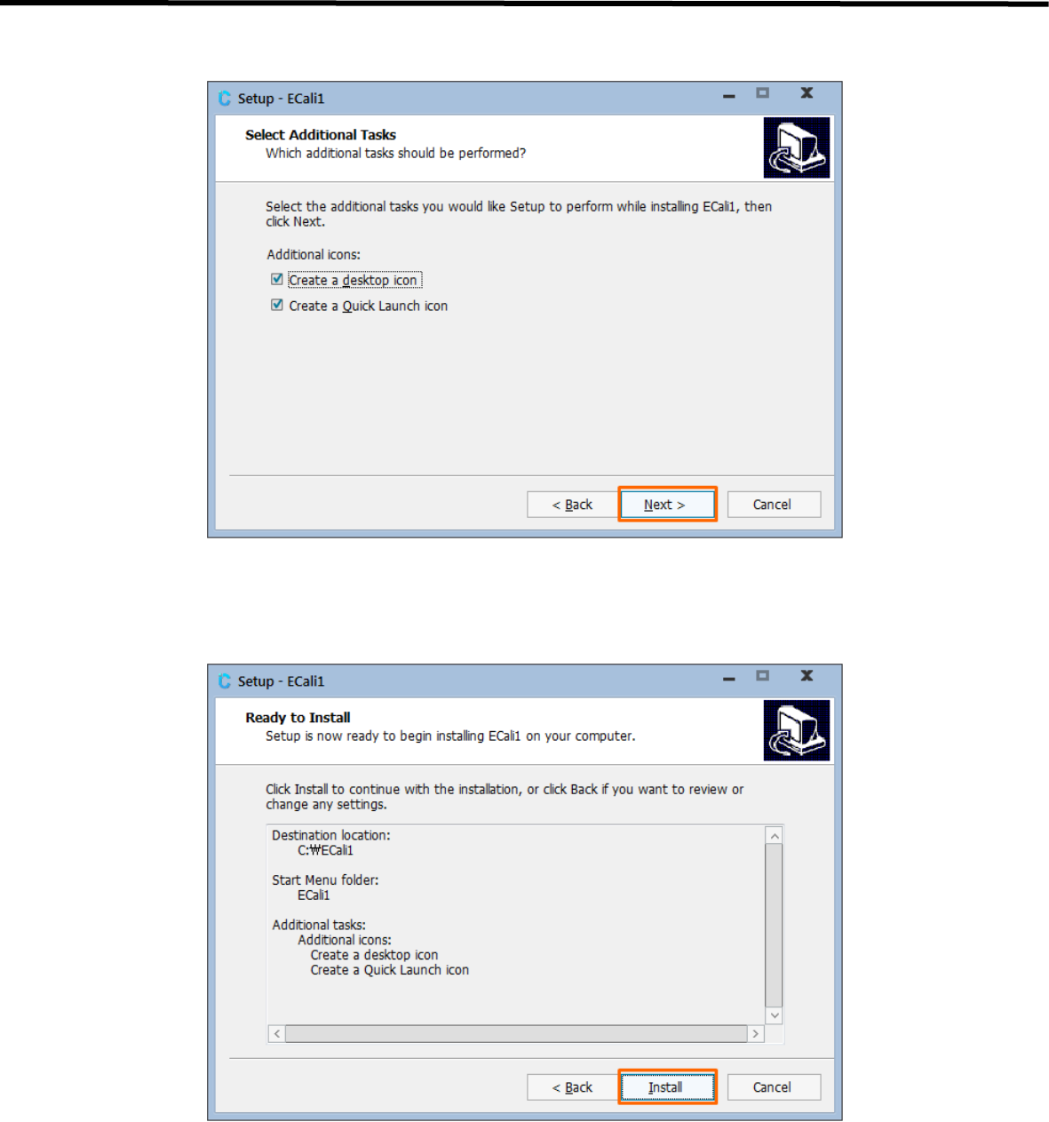
10-EVS1MADB001 40
Figure7.7. Additional Task Setting
Figure 7.8. Verification of Settings
EVS 3643 User’s Manual 7. How to Install
10-EVS1MADB001 41
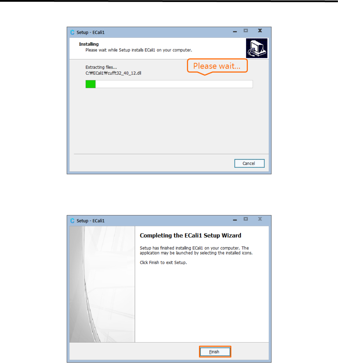
Figure 7.9. Installation Window
Figure7.10. Installation Window
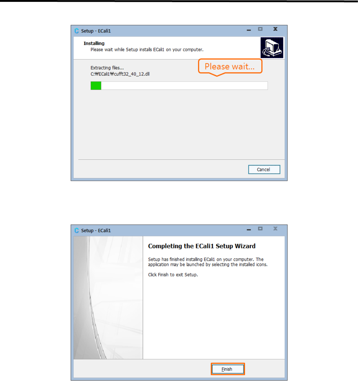
EVS 3643 User’s Manual 7. How to Install
10-EVS1MADB001 42
Figure 7.11. Installation Window
Figure7.12. Installation Window
EVS 3643 User’s Manual 7. How to Install
10-EVS1MADB001 43
7-1-4 Settings Post Installation
1) Windows 8 users must set ECali1 so that it runs as administrator.
①Right click (press and hold) the ‘ECali1.exe’ in the installation destination (in C:\Cali1 by default).
②‘Click ‘Properties’.
③Select ‘Advanced’ in the ‘Shortcut’ tab.
④Check the ‘Run as administrator’ box, then click ‘OK’
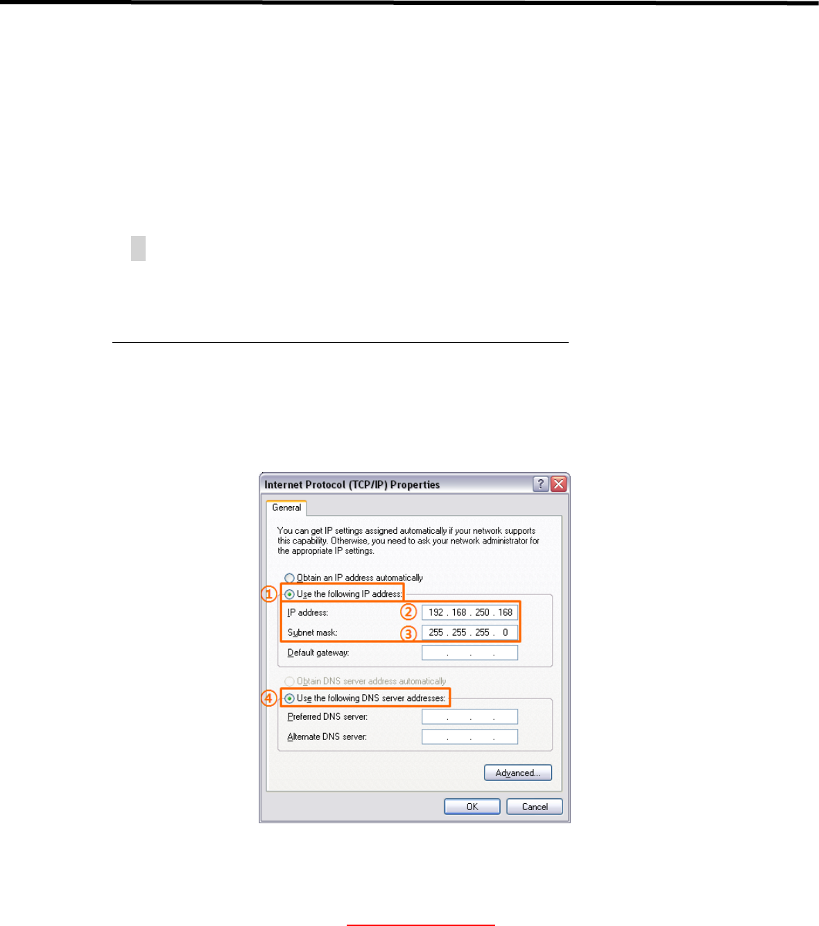
7-1-5 IP Address Configuration
It is required when using a EVS 3643 detector using an Ethernet Interface.
The IP Address of the Network Adapter connected with the EVS 3643 Detector System installed on the
PC should be configured.
For Windows 7, Control Panel – Network Connections – Network and Sharing Center – Manage Network
Connections on the left menu bar – Right click on the network connected to the Detector – Properties –
Double click Internet Protocol Version 4 (TCP/IPv4)
Figure7.13. IP Address Configuration
② IP Address: 192.168.250.XXX
For F600: 192.168.250.100
Others: 1 ≤ XXX ≤ 254 (Excluding 150 and 200)
③ Subnet mask: 255.255.255.0
EVS 3643User’s Manual 5. Operating procedure
10-EVS1MADB001 44
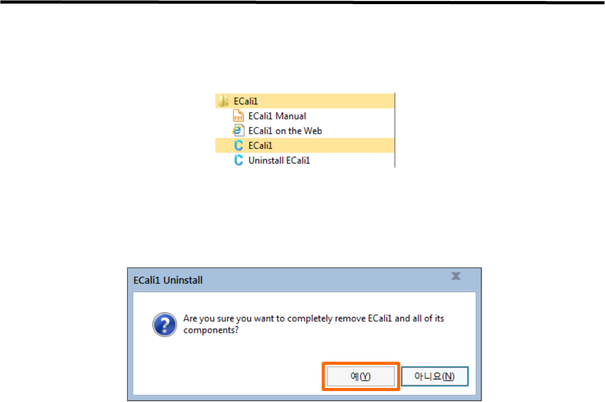
7-1-6 Uninstall ECali1
1) Click ‘Uninstall ECali1’ in Windows start menu – All Programs - ECali1
Figure 7.14. Uninstall ECali1
2) Click ‘Yes’ and proceed with uninstall when a window appears verifying the removal of the
program.
Figure7.15. Uninstall ECali1
EVS 3643 User’s Manual 7. How to Install
10-EVS1MADB001 45
7-2 ECali1 Operation & Detector Integration
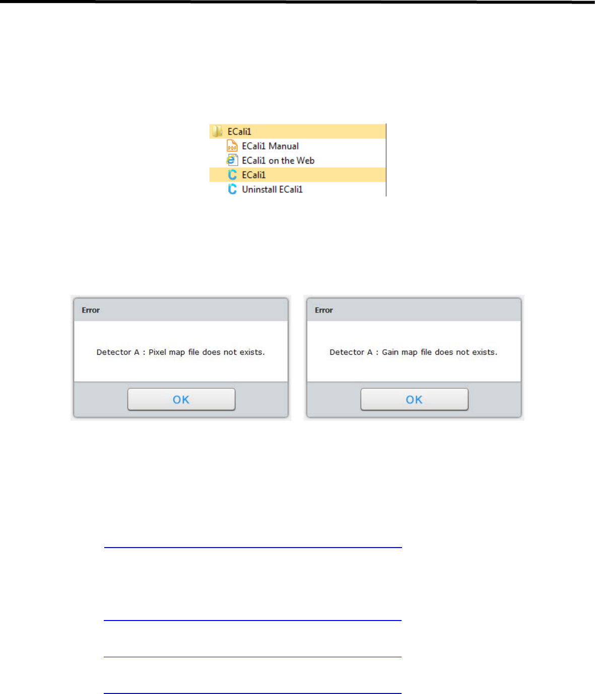
7-2-1 Program Start-up
In order to run the program, you can select ECali1 in Windows Menu – All Programs – ECali1
Folder, or by double clicking ECali1.exe in C:\ECali1 (or the customized installation path)
Figure7.16. ECali1 Start-up
Note
→An error notification as in Figure 7.17. Pixel / Gain map File Notification) will be presented during the
initial start-up of the program.
→It is a normal notification informing the absence of Pixel map file and Gain map file, so proceed by
clicking ‘OK’.
Figure 7.17. Pixel / Gain map File Notification
Note
Please install the additional software in accordance with the specification of your OS if the program does
not operate after proper installation
For Windows XP SP3, Windows 7, and Windows 8:
VC2008SP1 Runtime (vcredist_x86.exe)
http://www.microsoft.com/en-us/download/details.aspx?id=5582
For Windows XP SP2:
Wireless LAN API package
http://www.microsoft.com/en-us/download/details.aspx?id=2098
Microsoft Core XML Service (MSXML) 6.0
http://www.microsoft.com/en-us/download/details.aspx?id=3988
VC2008SP1 Runtime (vcredist_x86.exe)
http://www.microsoft.com/en-us/download/details.aspx?id=5582
EVS 3643 User’s Manual 7. How to Install
10-EVS1MADB001 46
For Windows XP SP1 or earlier OS:
ECali1 will only operate in Windows XP SP2 and later environments. Please install Service
Pack 2 or 3 if you are using Windows XP.
We do not guarantee proper operation of ECali1 in OS earlier than Windows XP
7-2-2 Detector Connection
1) The Detector which will be utilized should be registered prior to operating the program.
2) A Registration and Configuration window for the Detector will appear during the initial start-up of
the program.
3)This configuration window is available through Configuration in the Option menu, and please refers
to 1) Detector Configuration for detailed information.
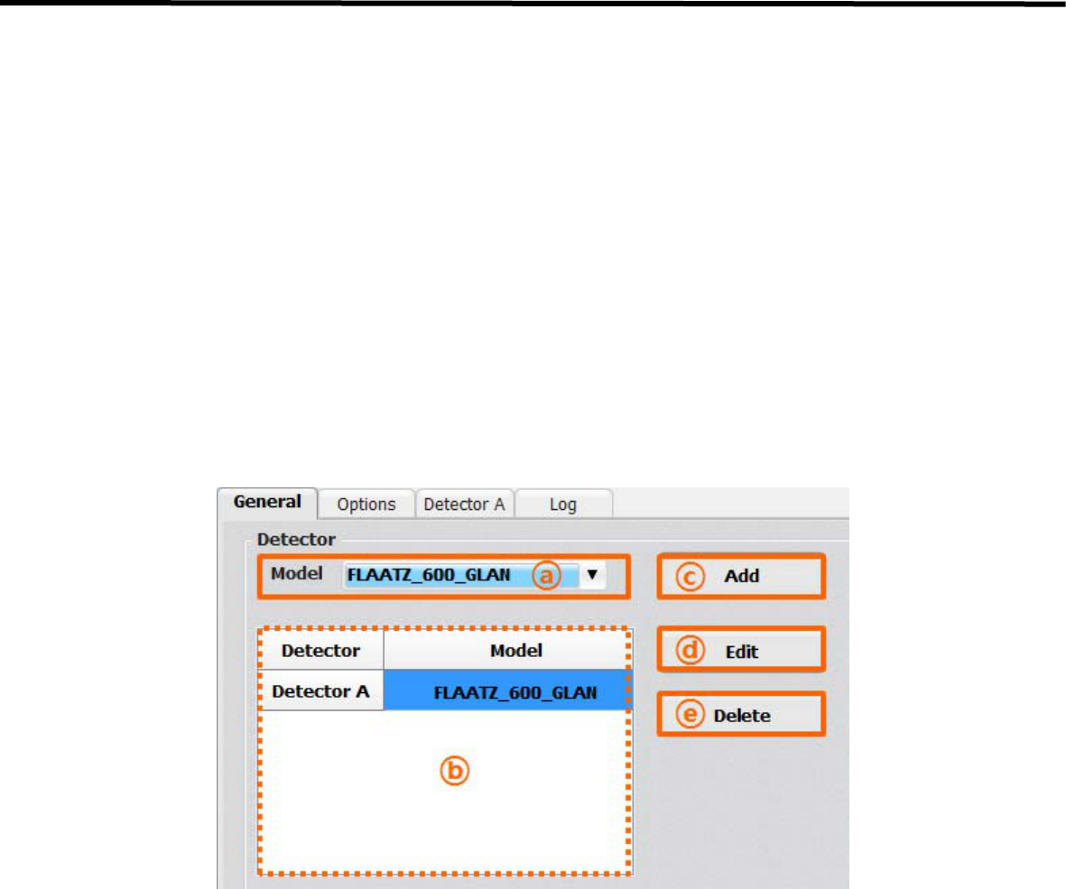
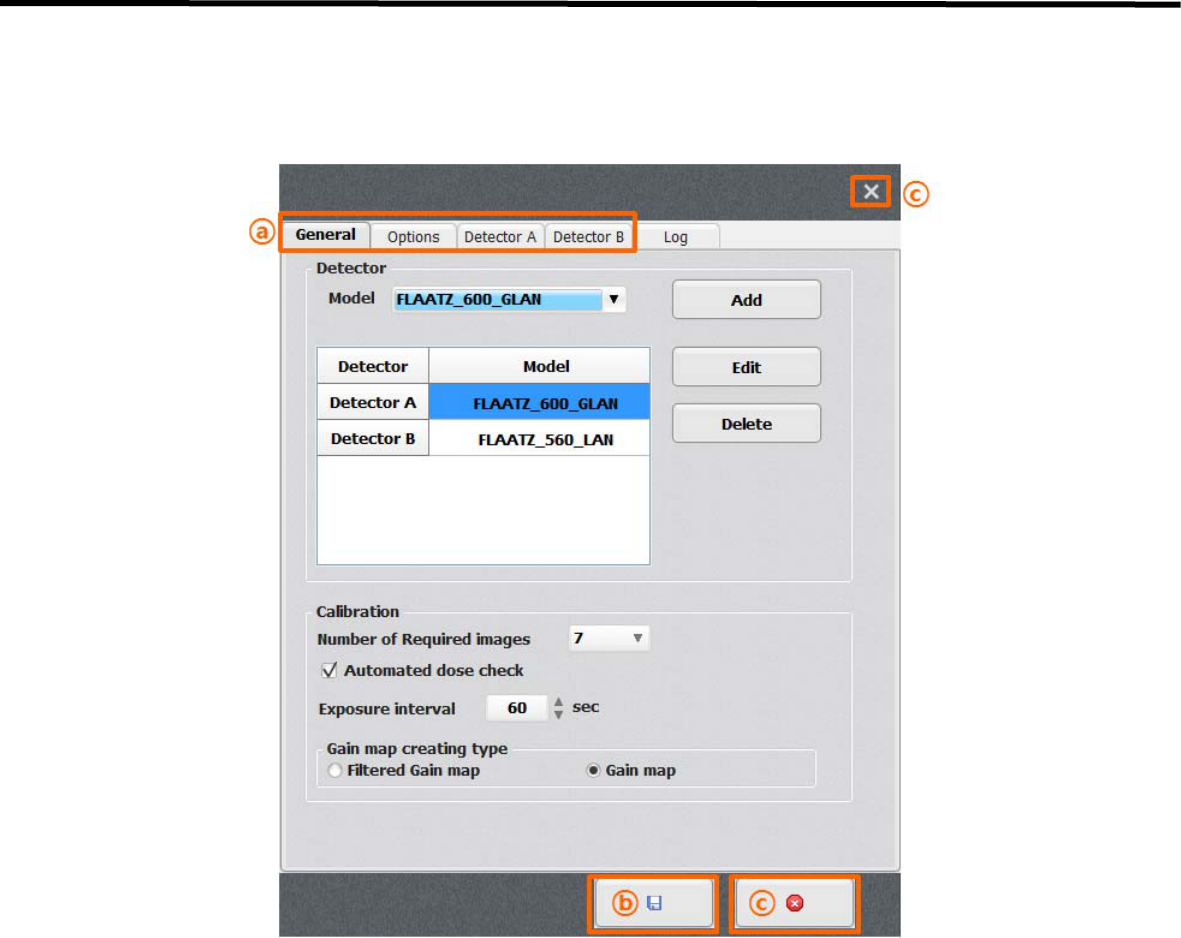
Figure7.18. Detector Registration
ⓑ displays the registered Detector.
If a specific item requires editing, select the Model to be edited in ⓐ and click ⓓ Edit.
Select a Model in ⓐ and click ⓒ Add in order to add a Detector.
The most recently registered model will be deleted if ⓔ Delete is selected.
EVS 3643 User’s Manual 7. How to Install
10-EVS1MADB001 47
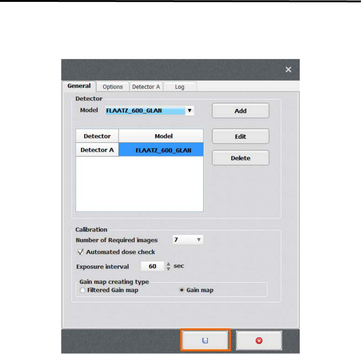
Changes in configurations must be saved.
Save the changes in configuration by selecting the save icon below
Figure 7.19. Configuration Save icon
When the save button is selected, a program restart message will appear.
Restart the program by selecting ‘OK’.
EVS 3643 User’s Manual 7. How to Install
10-EVS1MADB001 48
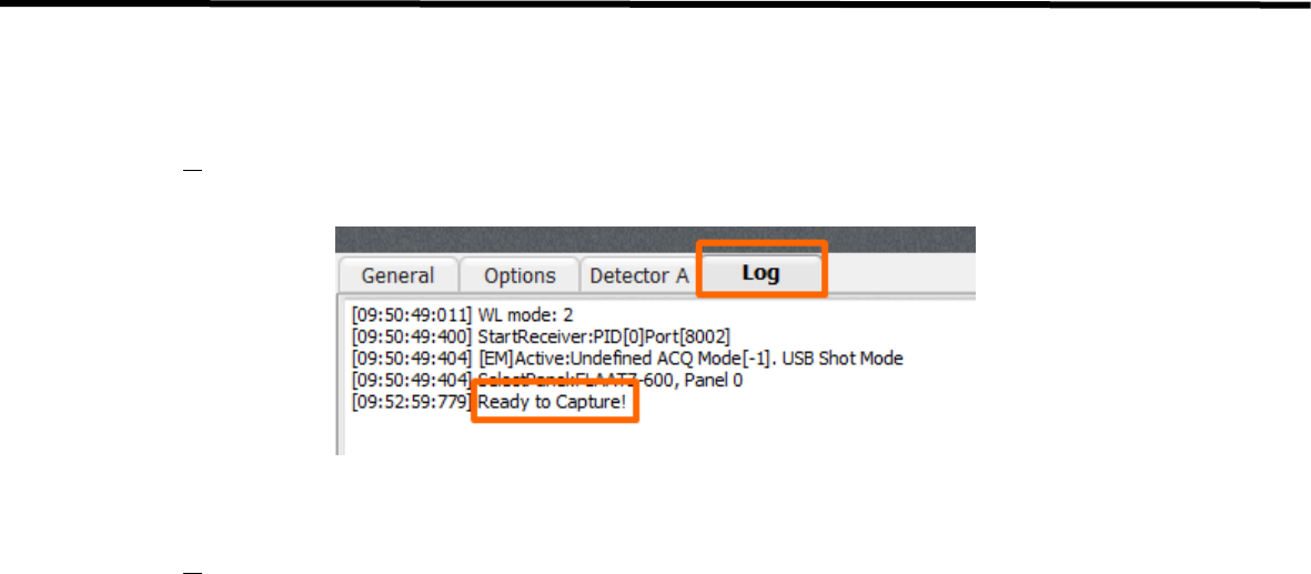
Verify Detector Connection after restarting the program.
Open the ‘Log’ tab after connecting and powering on all necessary devices including the Detector.
Figure7.20. Detector Connection Log
The Detector has been successfully integrated if a ‘Ready to Capture!’ appears in the window as
seen in the figure.
EVS 3643 User’s Manual 7. How to Install
10-EVS1MADB001 49
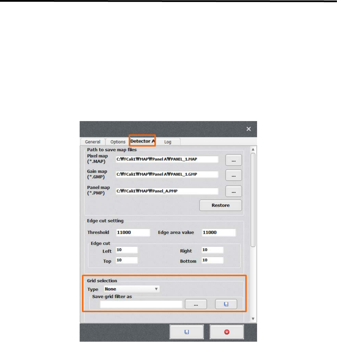
7-3 Grid Configuration
1)Grid type must be configured for each registered Detector..
2)The Grid type is set as ‘None’ by default, so this step may be skipped if a Grid isn’t used.
3) Grid configuration may be completed in the ‘Detector #’ tab.
# will be designated with alphabets of A, B, C, ….
Figure7.21. Grid Configuration
4 ) Please verify the Model and Grid of the registered Panel since a limited number of Detectors
may use the Grid with the use of multiple Detectors.
EVS 3643 User’s Manual 7. How to Install
10-EVS1MADB001 50
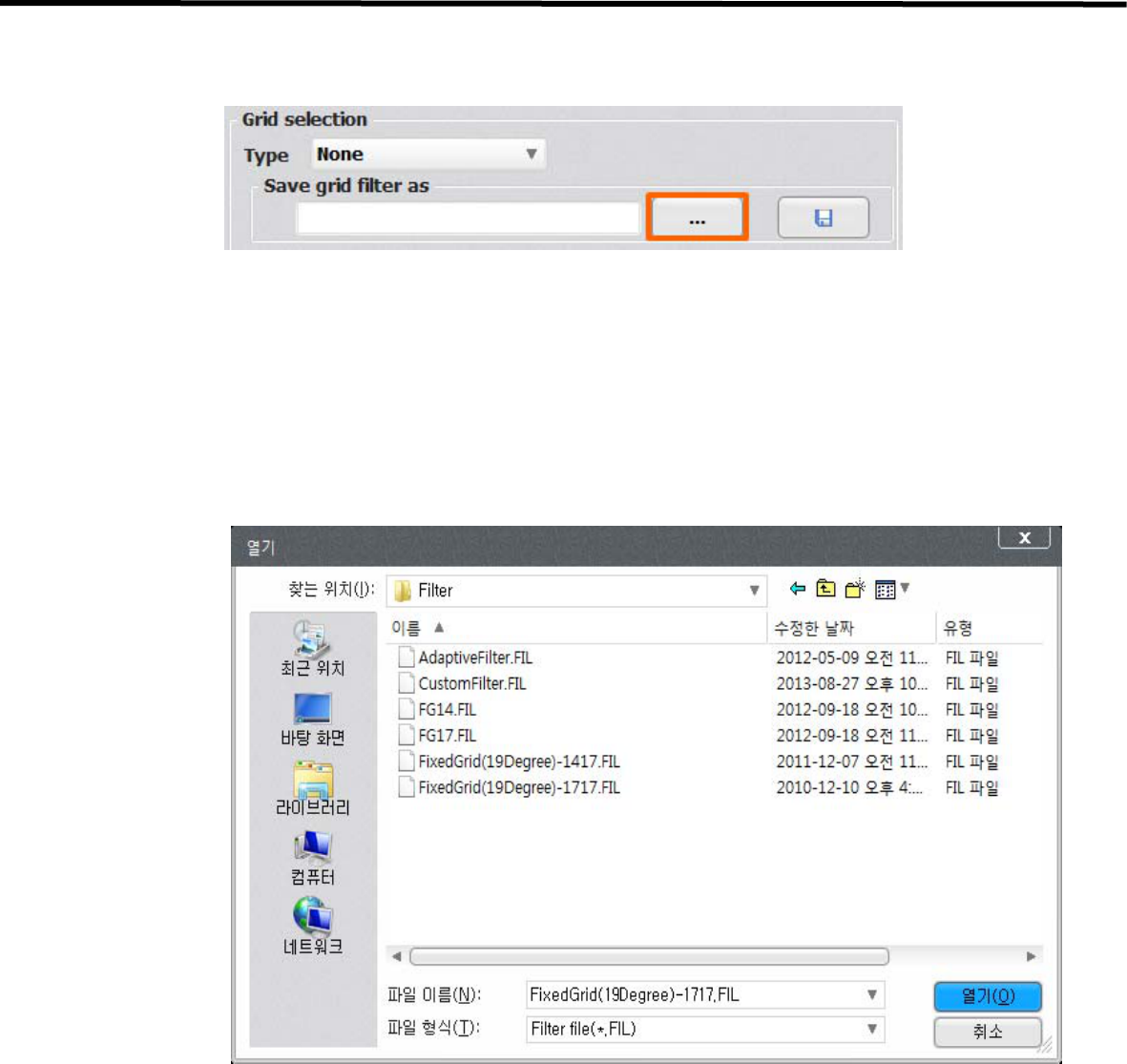
5) Filter file must be registered after the configuration of Type.
Figure7.22. Registering Grid Filter File
① Select the Filter file by selecting ‘…’ as in the figure.
② A file compatible with the configured Grid Type must be selected.
③ Filter file is located in the [ECali1 Installation Folder]\Filter Folder.
④ It is in the C:\ECali1\Filter folder by default.
Figure 7.23. Filter File
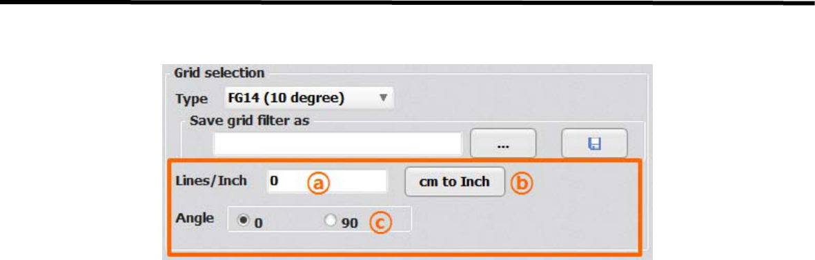
6) Input the ⓐ Lines/Inch and ⓒ Angle in accordance with the Grid Type. The ⓑ cm to Inch
button may be utilized to alter the units when entering the Lines/Inch, if the cm unit is known.
EVS 3643 User’s Manual 7. How to Install
10-EVS1MADB001 51
Figure7.24. Additional Grid Configuration
7) Save and restart the program after completing the configuration.
EVS 3643 User’s Manual 7. How to Install
10-EVS1MADB001 52
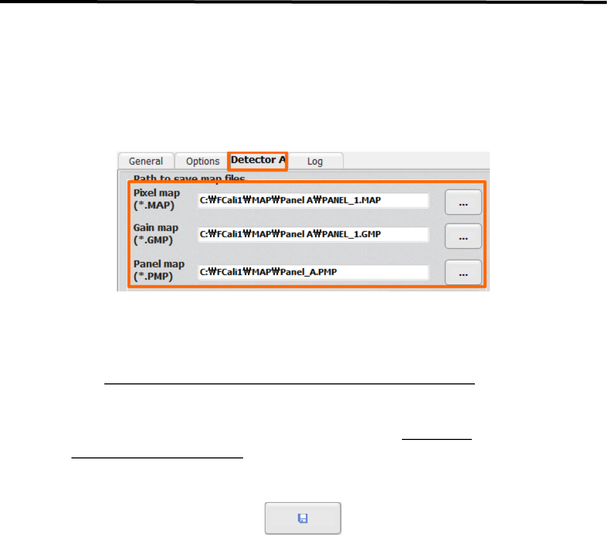
7-4 Map File Registration
Open the configuration tab for each registered Detector though Option Menu – configuration and
opening the Configuration window.
Figure7.25. MAP File Destination Configuration
Use the ‘…’ on the right or manually enter in a new directory to change the destination
name. Please set it as a file used or provided by the X-ray acquisition software.
Save the changes in configuration using the save button below after designating a
destination for all registered Panels.
Figure7.26. Save Button
ECali1 will automatically restart when the changes in configuration has been saved.
EVS 3643 User’s Manual 7. How to Install
10-EVS1MADB001 53
7-5 ECali1 UI Overview
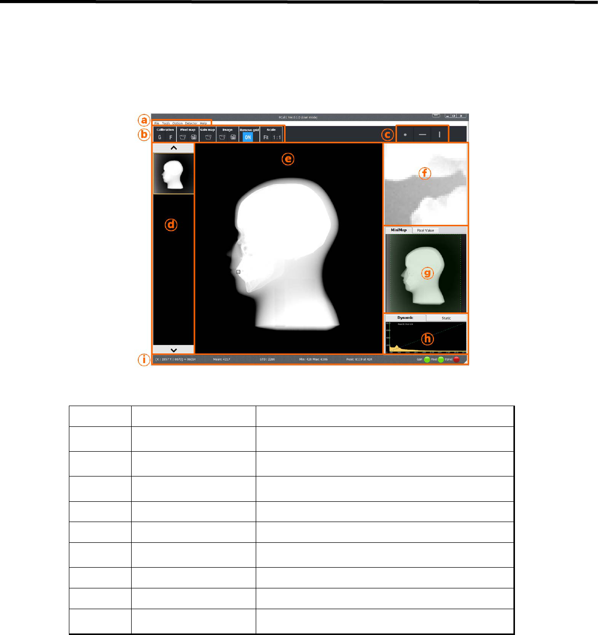
7-5-1 Main Screen of the Program
The main screen of ECali1 is as illustrated in [7.27].
Figure 7.27. Main Screen of ECali1
Category Title Reference
ⓐ Menu
Menu (p. 49)
ⓑ Toolbar
Toolbar (p. 53)
ⓒ Pixel Map Toolbar
Pixel Map Toolbar and Pixel Viewer (p. 66)
ⓓ Thumbnail Thumbnail (p. 67)
ⓔ Image Viewer Image Viewer (p. 68)
ⓕ Pixel Viewer
Pixel Map Toolbar and Pixel Viewer (p. 66)
ⓖ Mini Map / Pixel Value 7-7 Mini Map and Pixel Value (p. 70)
ⓗ Histogram Histogram (p. 71)
ⓘ Status Bar
Status Bar (p. 72)
EVS 3643 User’s Manual 7. How to Install
10-EVS1MADB001 54
1) Menu
Corresponds to ⓐ in [Figure 7.27] and comprised of 5 menus, which are File, Tools, Option,
Detector and Help.
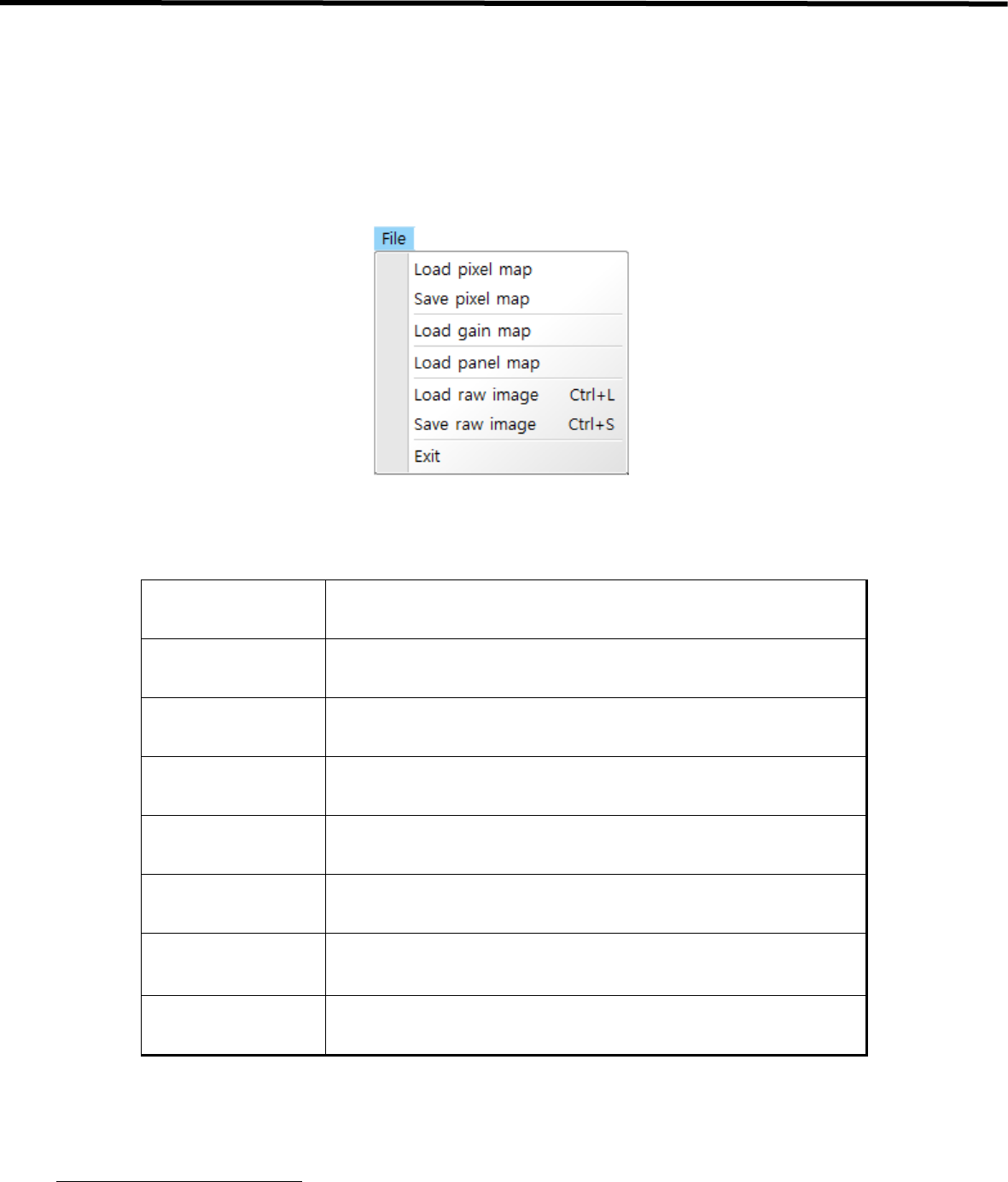
A. File Menu
Figure 7.28. File Menu
Table 7.1. File Menu Descriptions
Menu Descriptions
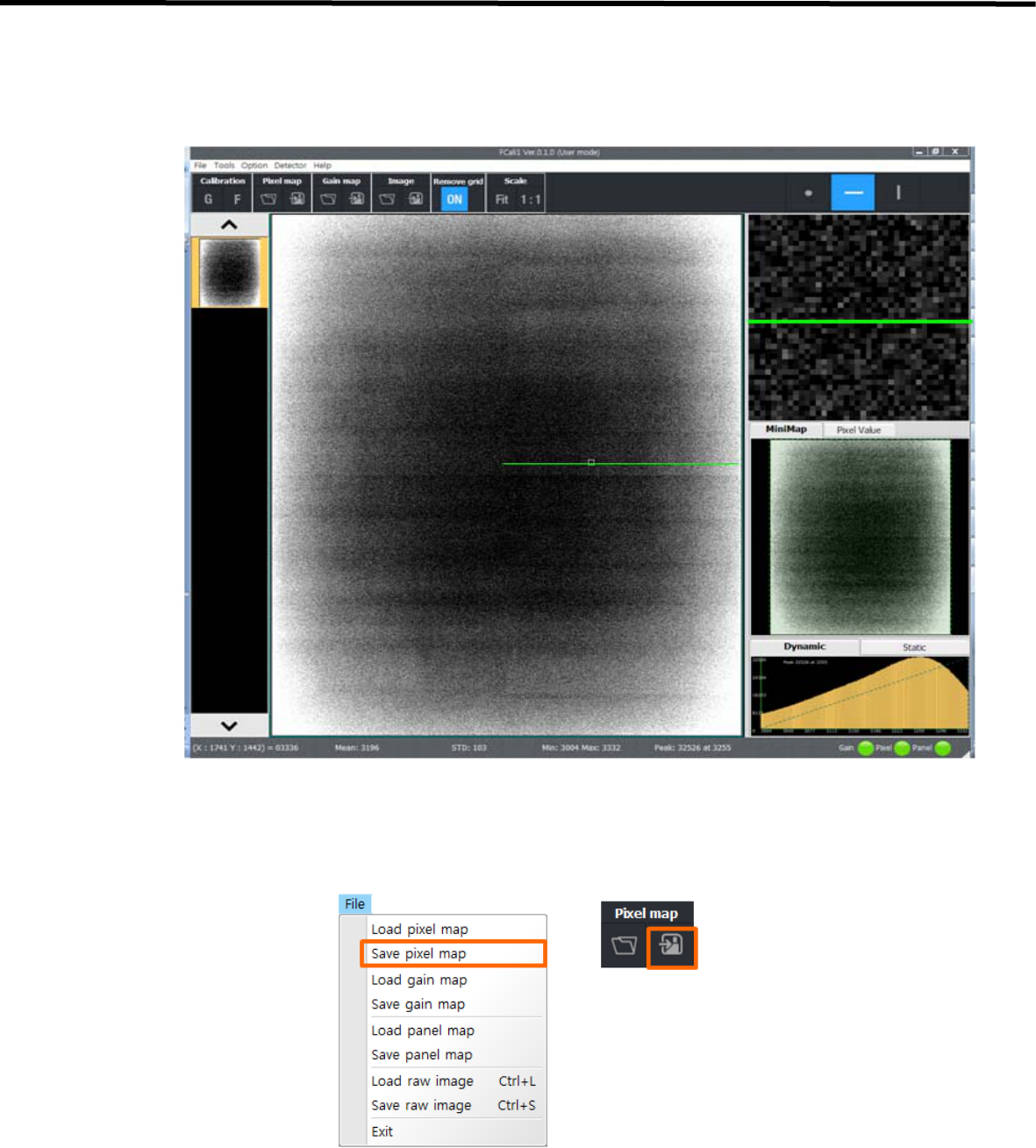
Load pixel map Loads the Pixel map file.
Save pixel map Saves the Pixel map file.
Load gain map Loads the Gain map file.
Load panel map Loads the Panel map file.
Load raw image Loads the RAW image file in .IMG1 format.
Save raw image Saves the currently selected image as a RAW image file in .IMG
format.
Exit Exits ECali1.
1 .IMG file: Image Data file that has 16 bit gray-level pixel value

EVS 3643 User’s Manual 7. How to Install
10-EVS1MADB001 55
B.Tools Menu
Figure 7.29. Tools Menu
Table 7.2. Tools Menu Descriptions
Menu Descriptions
Gain map calibration
Initiates the Gain Map Calibration.
Please refer to7-10 Gain Calibration for more details.
Create FGain map
Generates a Filtered Gain Map
2
using the currently loaded Gain Map.
Will not operate if the loaded Gain Map is a Filtered Gain Map.
The generated Filtered Gain Map is saved in the configured Gain Map
destination of the Detector (Panel) set in Configuration.
Filter calibration
Run the Grid Filter Calibration task.
Please refer to 오류! 참조 원본을 찾을 수 없습니다.. 오류! 참조 원본을 찾을
수 없습니다. for more details.
Filter calibration
using files
Run the Grid Filter Calibration using raw files.
Please refer to 오류! 참조 원본을 찾을 수 없습니다.. 오류! 참조 원본을 찾을
수 없습니다. for more details.
Scale Fit
Adjusts the magnifying ratio of the image displayed in the Image Viewer
domain.
Scale 1:1
Adjusts the magnifying ratio of the image displayed in the Image Viewer
domain to set the size of the image corresponding to its actual size.
The Pixel displayed on the screen will be identical to the actual Pixel of the
Detector.
Fixed Scale Saves the configured scale ratio in the current Image Viewer and applies it to
the subsequent images.
2 Filtered Gain Map: Gain Map maintaining the uniformity of the image even if the uniformity of the X-
ray source is different, by applying filtering to the Gain Map

EVS 3643 User’s Manual 7. How to Install
10-EVS1MADB001 56
C. Option Menu
Figure 7.30. Option Menu
Table 7.3. Option Menu Descriptions
Menu Descriptions
Configuration
Opens the Configuration window.
Please refer to. 7-12 Configuration for more details regarding
Configuration.
Engineer Mode Initiates Engineer Mode of ECali1 for Advanced Configuration.
Requires the input of a password.
Terminal Mode Initiates the Terminal Emulator which allows the internal
configuration of the Detector.
Remove grid
ON/OFF
Sets the Grid Pattern Algorithm application. If a check mark (√) is
available as noted in the figure, the algorithm is applied (ON). This
category must be ON if Grid is utilized.
AED – Acq mode
Activates AED mode to allow image acquisition.
AED – Stay mode
Inactivates AED mode and reverts to Standby.
Ready
Converts the status of the Detector to Ready.
Exposure
The Detector performs Exposure.
Ready cancel
Cancels the Ready status of the Detector and reverts to Standby.
EVS 3643 User’s Manual 7. How to Install
10-EVS1MADB001 57
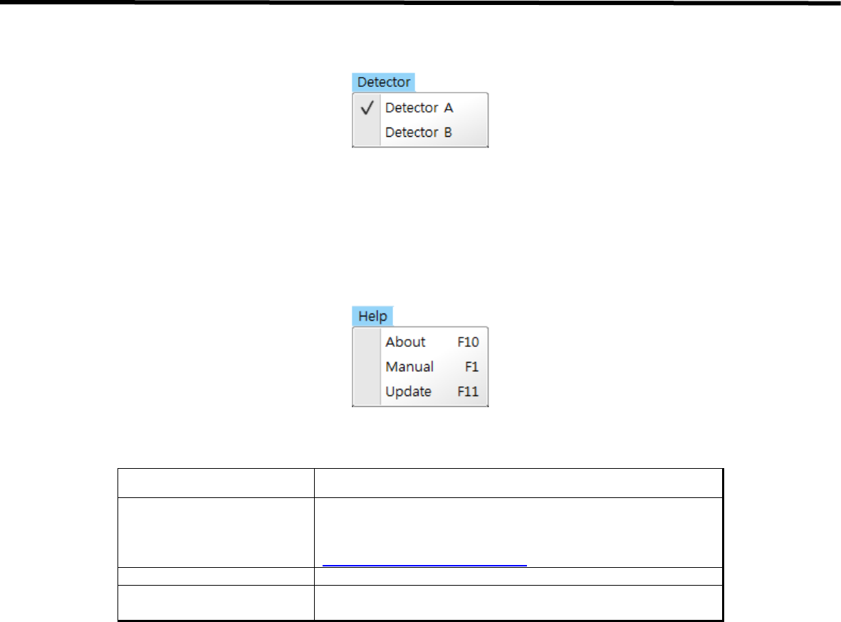
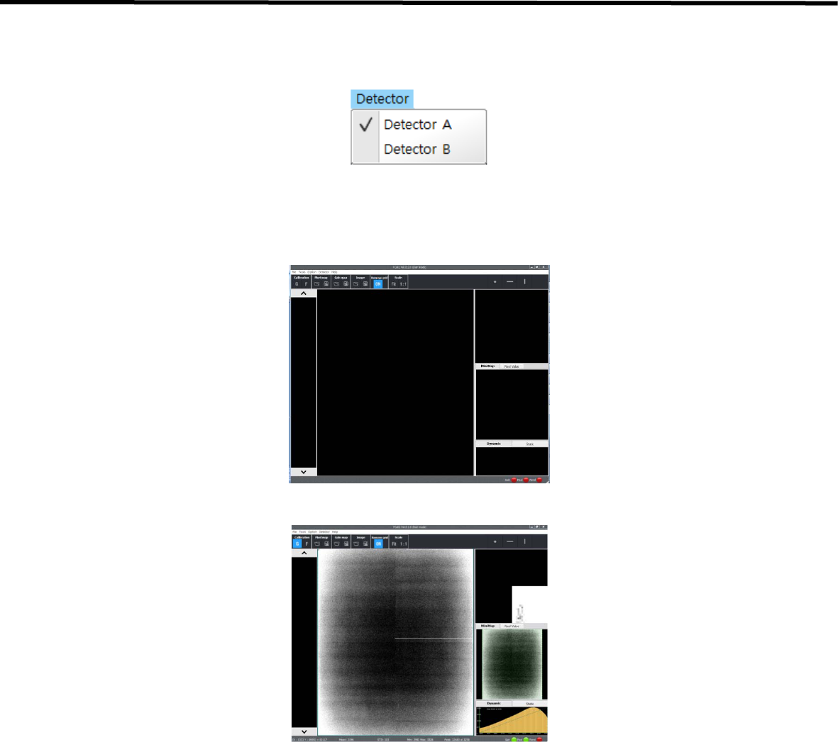
D. Detector Menu
Figure 7.31. Detector Menu
① Select the active Detector from the registered Detector (Panel).
② Number of Menus reflecting the number of registered Detectors through Option – Configuration
- General will be generated. Only one Detector may be selected
E. Help Menu
Figure7.32. Help Menu
Table 7.5. Help Menu Descriptions
Menu Descriptions
Manual
Displays the ECali1 manual.
The manual is in PDF format, thus Adobe Reader program
will be required.
http://get.adobe.com/kr/reader/
About Will display the version information of ECali1.
Check update * Requires internet connection.
Checks and installs updates for ECali1.
EVS 3643 User’s Manual 7. How to Install
10-EVS1MADB001 58
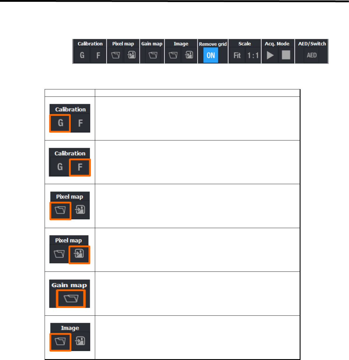
7-5-2 Toolbar
Corresponds to ⓑ in [7.27] and provides most used menus as Toolbar icons.
Figure 7.33. Toolbar
Table 7.6. Toolbar Icon Descriptions
Icon Descriptions
Performs Gain map calibration.
Corresponds to the Gain map calibration in the Tools Menu.
Performs Grid Calibration.
Corresponds to the Grid map calibration in the Tools Menu.
Loads and applies the Pixel map file.
Corresponds to the Load pixel map in the File Menu.
Stores the currently applied Pixel map as a file.
Corresponds to the Save pixel map in the File Menu.
Loads and applies the Gain map file.
Corresponds to the Load Gain map in the File Menu.
Loads and displays the projected image from the file.
Corresponds to the Load raw image in the File Menu.
EVS 3643 User’s Manual 7. How to Install
10-EVS1MADB001 59
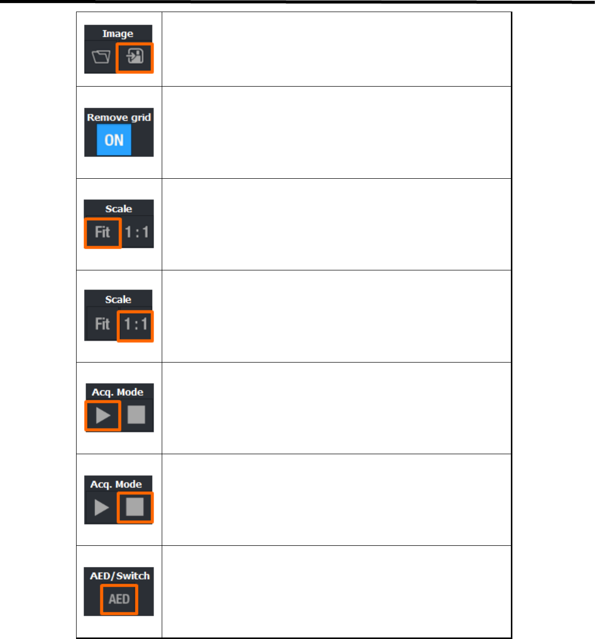
Stores the currently projected image as a file.
Corresponds to the Save raw image in the File Menu.
This category must be ON when using the Grid.
Corresponds to the Remove grid ON/OFF in the Tools Menu.
Adjusts the magnifying ratio of the image in ⓔ to fit on screen.
Corresponds to the Scale Fit in the Tools Menu.
Adjusts the magnifying ratio of the image in ⓔ to actual size of the
image.
Corresponds to the Scale 1:1 in the Tools Menu.
* Only available when the selected Detector (Panel) supports AED mode.
* Only available when AED mode is active.
Changes the status of the Detector to acquire images. Corresponds to
the AED - Acq mode in the Options Menu.
* Only available when the selected Detector (Panel) supports AED mode.
* Only available when AED mode is active.
Converts the Detector to Standby mode.
Corresponds to the AED - Stay mode in the Options Menu.
* Only available when the selected Detector (Panel) supports AED mode.
This category must be activated when using AED mode.
EVS 3643 User’s Manual 7. How to Install
10-EVS1MADB001 60
7-5-3 Pixel Map Toolbar and Pixel Viewer
Corresponds to ⓒ and ⓕ in [Figure 7.27], and utilized when creating a Pixel Map.
Figure7.34. Pixel Map Toolbar
Figure 7.35. Pixel Viewer
The selected area from the Image Viewer will be magnified and displayed in the Pixel Viewer.
Please refer to 7-11 Pixel Correction for more details and methods of generating Pixel Maps.
EVS 3643 User’s Manual 7. How to Install
10-EVS1MADB001 61
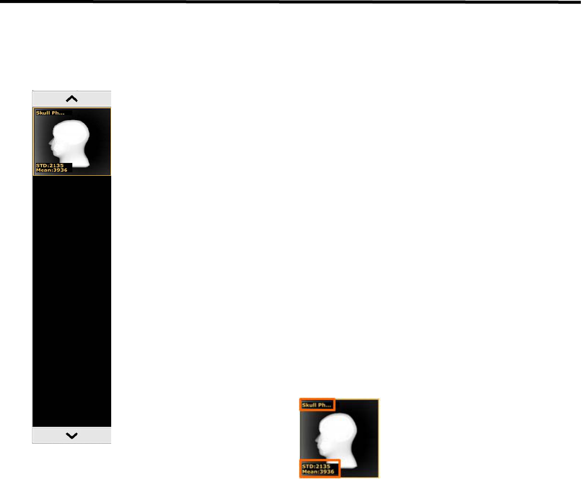
7-5-4 Thumbnail
Corresponds to ⓓ in [Figure 7.27].
Displays the Thumbnail of the projected image, and allows the user to select a specific image
between multiple images.
If there are a significant number of projected images, a scroll button on the top and bottom
allows the user to select a specific image.
Select the Thumbnail to be deleted and select ‘Delete’ if a re-projection is required during the
calibration. The selected image will be deleted and a re-projection may be performed.
The following information will be displayed if an image is loaded from a file.
The file name will be displayed on the top left.
STD: Standard Deviation Value of the Pixel value of the image.
Mean: Mean value of the pixel value of the image.
Figure 7.37. Thumbnail Information
Figure 1.36. Thumbnail
EVS 3643 User’s Manual 7. How to Install
10-EVS1MADB001 62
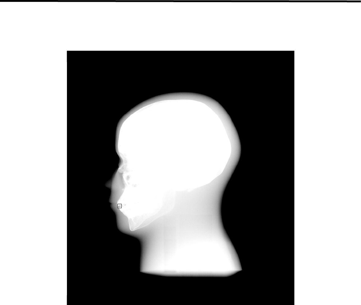
7-6 Image Viewer
Corresponds to ⓔ in [Figure 7.27].
Figure 7.38. Image Viewer

EVS 3643 User’s Manual 7. How to Install
10-EVS1MADB001 63
Displays the projected image and supports the following functions.
Table 7.7. Image Viewer Function & Control Method
Function Control Method
Magnify Roll the mouse wheel forward in the Image Viewer.
Reduce Roll the mouse wheel backwards in the Image Viewer.
Move Image Left click, drag and drop the image in the Image Viewer.
W/L3 Width Increase Drag the right mouse button down.
W/L Width Reduction Drag the right mouse button up.
W/L Left Shift Drag the right mouse button left.
W/L Right Shift Drag the right mouse button right.
Magnify Pixel Double click the left mouse button in the area within the Image Viewer
in order to magnify the selected are in the Pixel Viewer screen.
3 W/L: Window Leveling
EVS 3643 User’s Manual 7. How to Install
10-EVS1MADB001 64
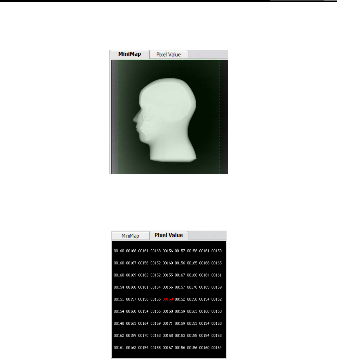
7-7 Mini Map and Pixel Value
Corresponds to ⓖ in [Figure 7.27]
7-7-1 Mini Map
Figure 7.39. Mini Map
Allows the users to verify the area currently being viewed in the Image Viewer. The area within the
green dotted boarder is the area currently displayed in the Image Viewer.
7-7-2 Pixel Value
Figure 7.40. Pixel Value
Displays the pixel value of the location the mouse cursor is hovering in the Image
Viewer or the Pixel Viewer.
EVS 3643 User’s Manual 7. How to Install
10-EVS1MADB001 65
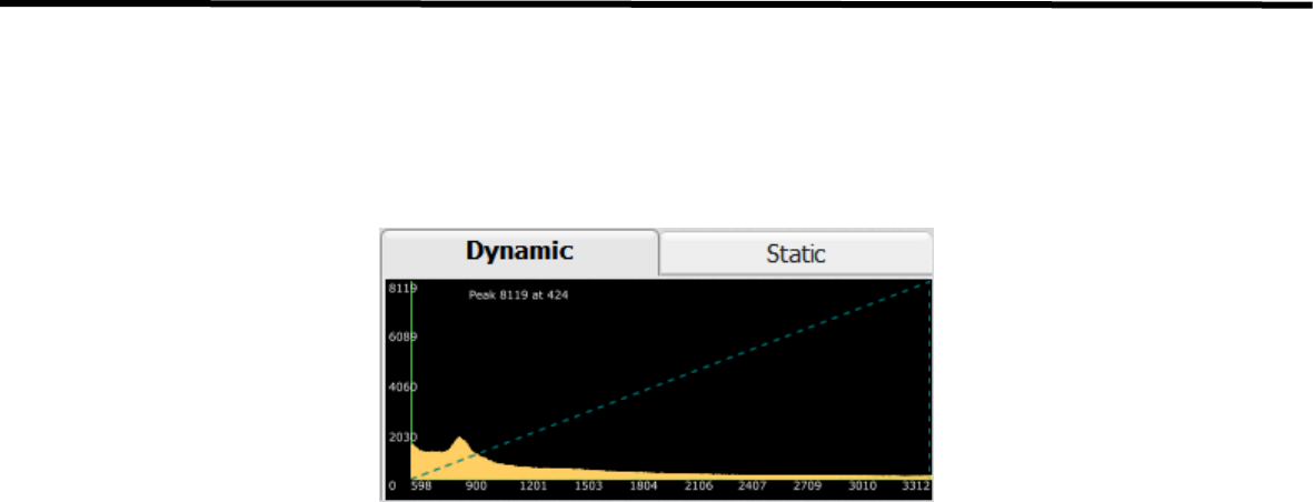
7-8 Histogram
Corresponds to ⓗ in [Figure 7.24]
Displays the Histogram of the selected image
Figure7.41. Histogram
Supports Dynamic or Static mode subsequent to the Windows Leveling conditions
7-8-1 Dynamic
The minimum and maximum values will be fixed while the Histogram values may be adjusted if
Window Leveling is attempted in the Image Viewer while in Dynamic mode.
7-8-2 Static
The Histogram values will be fixed while the minimum and maximum values may be adjusted if
Window Leveling is attempted in the Image Viewer while in Static mode.
EVS 3643 User’s Manual 7. How to Install
10-EVS1MADB001 66
7-9 Status Bar
Corresponds to ⓘ in [Figure 7.27]
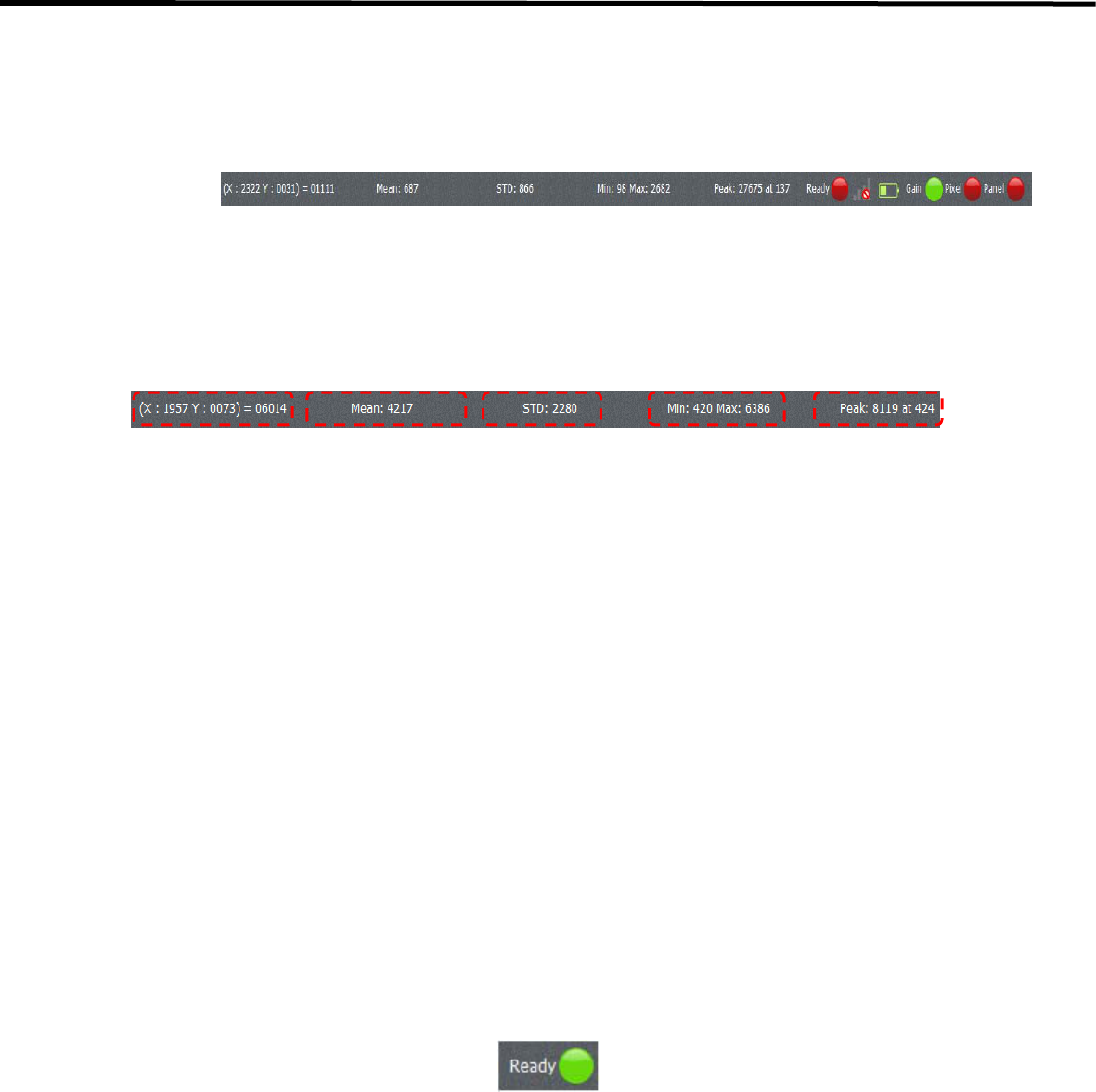
7-9-1 Image Information Display
Displays various information of the image
① Current axis and Pixel value of the mouse cursor
Displayed as (X : [X Axis] Y : [Y Axis]) = [Pixel Value]
② Mean: Mean Pixel Value of the image
③ STD: Standard Deviation of the Pixel value of the image
④ Min: Minimum value of the image Histogram
⑤ Max: Maximum value of the image Histogram
⑥ Peak: The Peak value and its Position of the image Histogram
Displayed as [Peak Value] at [Position]
7-9-2 Detector Status Display
* Supports only Ethernet Type and F600.
A green light will be displayed if the Detector is able to take a projection and a red
light will be displayed if the Detector is unable to take a projection.
Figure7.42. Status Bar
① ② ③ ④ ⑤
EVS 3643 User’s Manual 7. How to Install
10-EVS1MADB001 67
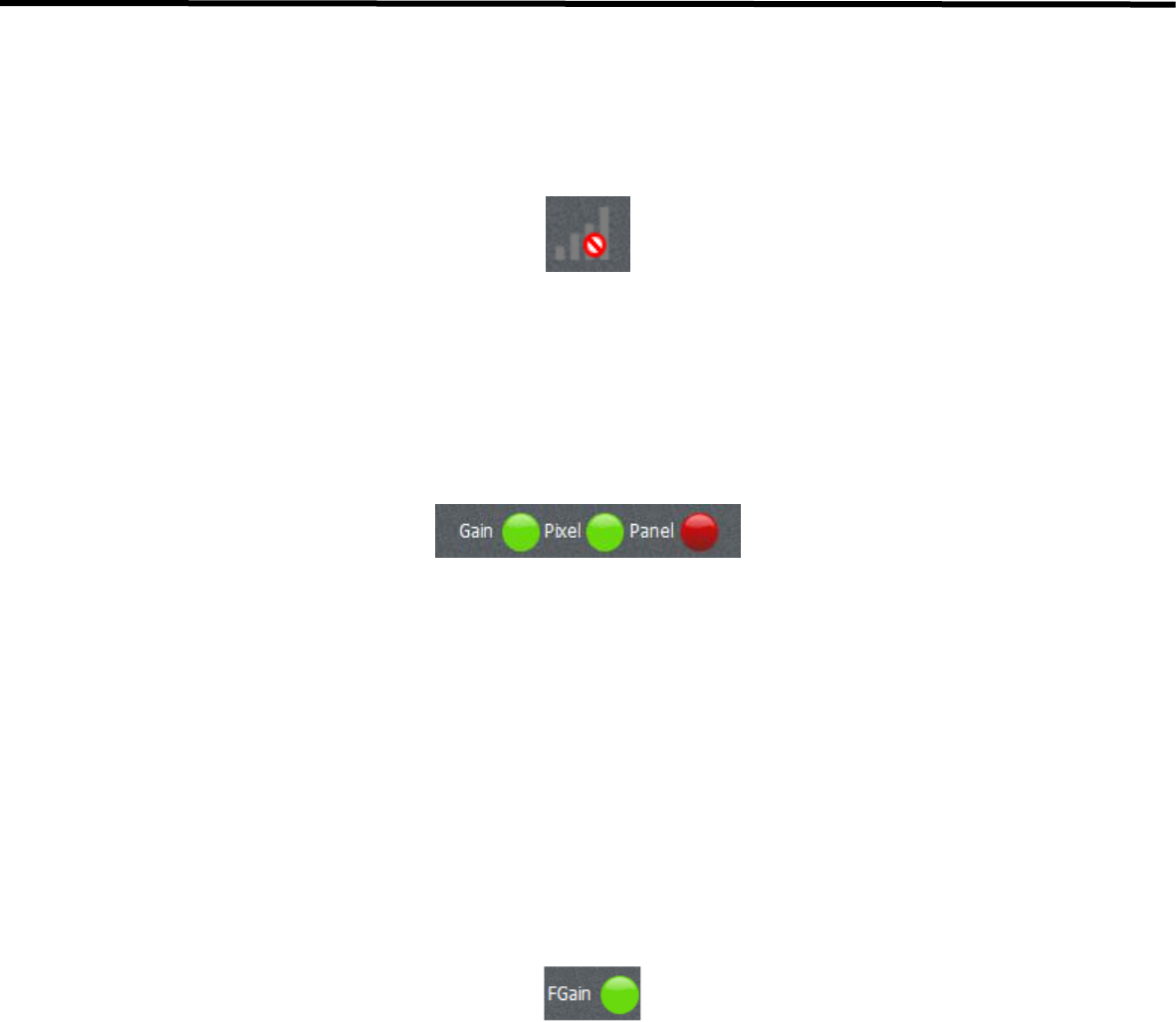
7-9-3 Wireless Information Display
* Support only Wireless Detector.
Information displayed when using a Wireless data communication.
7-9-4. Map File Loading Display
Green light will be displayed if a Map file required for Calibration has been loaded and the
red light will be displayed if it has not been loaded.
Gain: Gain Map Loading
Pixel: Pixel Map Loading
Panel: Panel Map Loading
If a Filtered Gain Map has been loaded in place of a Gain Map, the following
FGain will be displayed.

EVS 3643 User’s Manual 7. How to Install
10-EVS1MADB001 68
7-10 Gain Calibration
Gain Calibration Procedure will update or modify the x-ray characteristics to be combined
at the field to enhance the acquired image quality.
7-10-1 Gain Calibration Preparation
1)Detector and Grid Configuration
The Detector and Grid configuration must be completed prior to performing Gain
Calibration. Please refer to for details pertaining to the configuration.
2)MAP Data Location Configuration
The provided Pixel Map (*.MAP) and Gain Map (*.GMP) should be Loaded prior to
performing Gain Calibration. The destination location of the Map file provided by the
X-ray image acquisition software (EConsole1 and etc.) should be registered in
configuration.
Please refer to
7-4 Map File Registration for more details

EVS 3643 User’s Manual 7. How to Install
10-EVS1MADB001 69
7-10-2 Gain Calibration
Actual X-ray must be shot to project an image in order to perform Gain Calibration.
The Gain Calibration projection conditions are as follows. [Ta ble 7 - 8 ]
Table 7.8. Gain Calibration Condition
Conditions Descriptions
Grid application
Projection must be taken without the application of Grid.
(Cautions) The Grid Type must be set ‘None’ in Configuration -
Detector - Grid selection - Type before Gain Calibration, and must
be restored after Gain Calibration.
Subject Projection must be done without a subject
X-ray exposure X-ray exposure is required
X-ray radiation dose
Adjust the mean pixel value of the projected image to be between
3,000 ~ 4,000
X-ray Condition example) 70kVp, 200mA, 2mAs
SID Stand: 150 cm, Table: 100 cm
Number of
projections
Default Value: 7 counts
Configuration possible in Configuration - General - Calibration -
Count.
Projection interval
Default Value: 60 Seconds
Configuration possible in Configuration - General - Calibration -
Interval.
Other things
Collimator should be open maximally
X-ray should be set to be exposed in the whole Detector
Detector should be aligned in the center
EVS 3643 User’s Manual 7. How to Install
10-EVS1MADB001 70
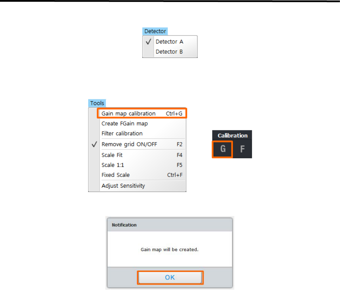
1) Detector Selection
Select the Detector to perform the Gain Calibration from the Detector Menu.
Figure 7.43. Detector Selection
2) Starting Gain Map Calibration
Next, select Gain map calibration from Tools Menu or select the shortcut icon.
Figure7.44. Starting Gain Calibration
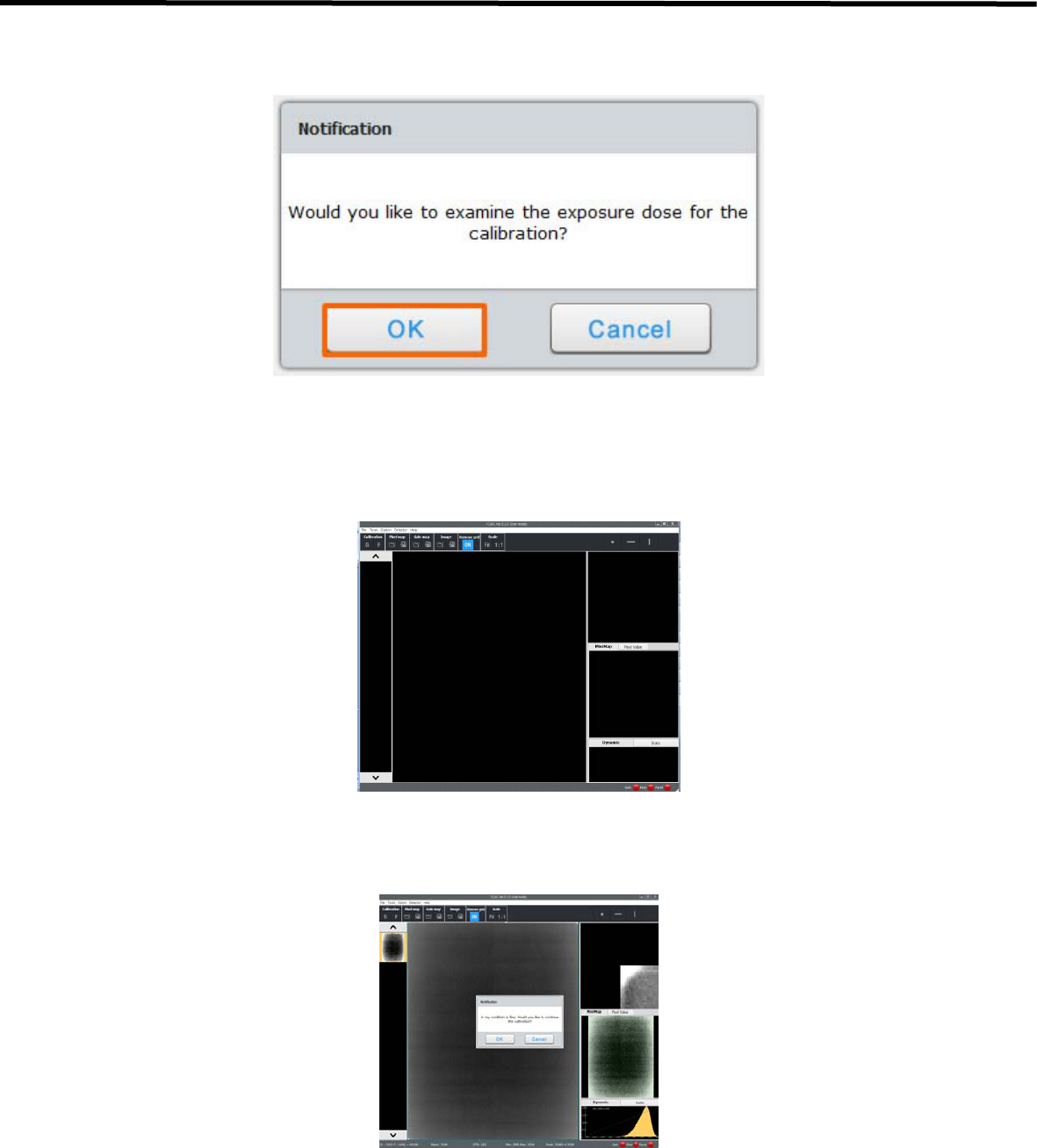
A notification message will appear. Select ‘OK’.
Figure 7.45.. Gain Calibration Start Notification
EVS 3643 User’s Manual 7. How to Install
10-EVS1MADB001 71
Next, ECali1 alerts whether the radiation dose is appropriate or whether it should be automatically
calculated. Proceed by selecting ‘OK’.
Figure 2. X-ray Radiation Dose Check Activation
Next, a main screen will appear.
Proceed with the X-ray projection at this point in order to acquire an image.
Figure 7.473. Projection Standby Main Screen
The program automatically determines the appropriateness of the X-ray radiation dose when the
image is acquired.
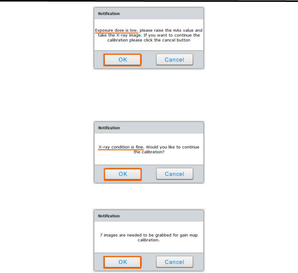
Figure7.48. X-ray Radiation Dose Verification Notification
EVS 3643 User’s Manual 7. How to Install
10-EVS1MADB001 72
Figure7.49. Notification for Low X-ray Radiation Dose
If provided with a notification of low radiation dose, please select ‘OK’ then increase the X-ray
radiation dose and re-project.
A notification will also appear if the X-ray radiation dose is high. Please select ‘OK’ then reduce the X
ray radiation dose and re-project.
Figure 7.50. Notification for Appropriate X-ray Radiation Dose
If the X-ray radiation dose is appropriate, please select ‘OK’ and proceed with the projections.
Figure 7.51. Notification Informing 7 Images Requirement
A notification informing the requirement of 7 images will appear. The required number of images may
be set in Configuration.
EVS 3643 User’s Manual 7. How to Install
73
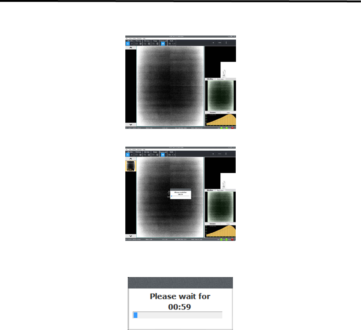
Select ‘OK’ and proceed with the projections of 7 images.
Figure 7.52. Starting the Gain Calibration Projection
Figure7.53. Standby post Projection of 1 Image
Stand by until the next designated projection after the initial projection.
Figure7.54. Projection Standby Timer
The next projection will take place after the projection standby timer disappears. The projection
standby time may be set in configuration.
EVS 3643 User’s Manual 7. How to Install
10-EVS1MADB001 74
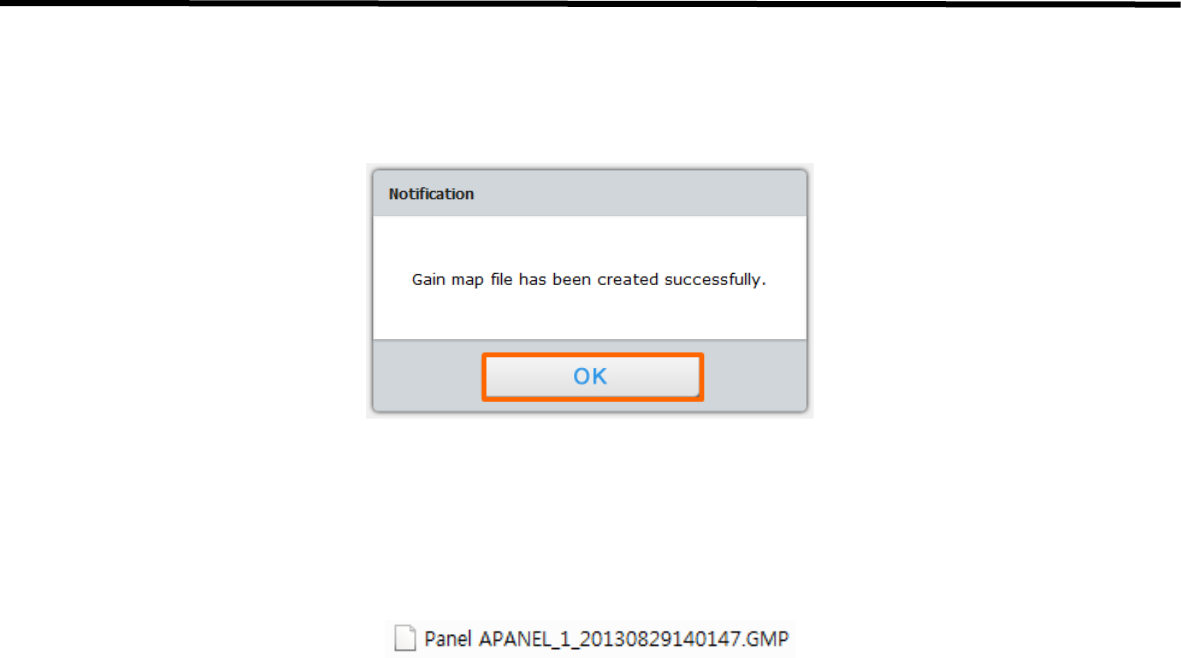
The Gain Calibration results are automatically saved as Gain Map (*.GMP) when all required images are
projected and the existing files are backed-up.
Figure7.55. Notification for Gain Calibration Completion
The existing GMP files are backed up in the [ECali1 Installation Folder]\MAP folder.
The file name is as follows. [7-56]
Figure7.56. Example of a Back-up File

EVS 3643 User’s Manual 7. How to Install
10-EVS1MADB001 75
7-11 Pixel Correction
If there are pixel defects or line defects needed to be calibrated, users can correct them manually.
7-11-1 Pixel Correction Preparation
1) Detector and Grid Configuration
The Detector and Grid configuration must be completed prior to performing Pixel correction
2)Map Data Location Configuration
The provided Pixel Map (*.MAP) should be Loaded prior to performing Pixel Correction.
The destination location of the Map file provided by the X-ray image acquisition
Software (EConsole1 and etc.) should be registered in Configuration.

EVS 3643 User’s Manual 7. How to Install
10-EVS1MADB001 76
7-11-2 Pixel Correction Performance
At least 1 count of RAW image acquired through X-ray Exposure is required to perform Pixel Correction.
Table 7.4. Pixel Correction Conditions
Condition Descriptions
Grid application Projection must be taken without the application of Grid
Subject Projection must be done without a subject
X-ray exposure X-ray exposure is required
Number of
projection
More than 1 count.
(One for check and correct defects, and others to verify
correction)
Other things Collimator should be open
EVS 3643 User’s Manual 7. How to Install
10-EVS1MADB001 77
1) Detector Selection
Select the Detector to perform the Pixel Correction from the Detector Menu.
Figure7.56. Panel Selection
2) Pixel Correction
Acquire the image by performing an X-ray projection from the main screen.
Figure 7.57. Projection Standby Screen
Figure 7.58. Image Acquisition Screen post Projection
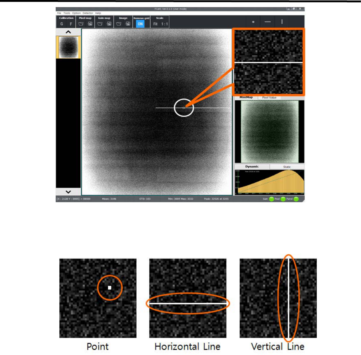
EVS 3643 User’s Manual 7. How to Install
10-EVS1MADB001 78
Figure 7.59. Display the Horizontal Line Defect Area in Pixel Viewer
A defect of a point or line may exist for each Detector. [7-59] illustrates a Horizontal Line Defect.
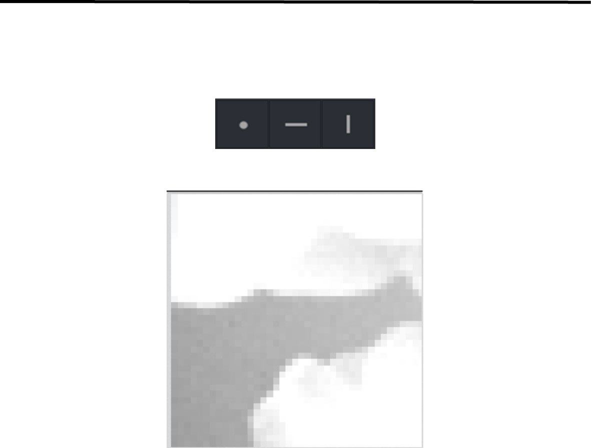
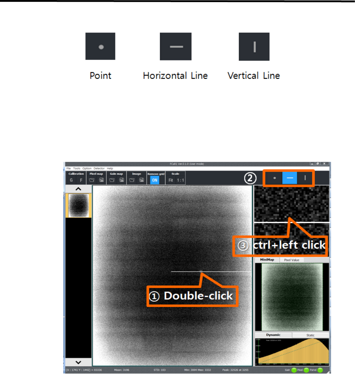
There are 3 types for Pixel Correction.
Figure 7.60. Pixel Defects
EVS 3643 User’s Manual 7. How to Install
10-EVS1MADB001 79
The following are utilized to perform Pixel Correction. [Figure7-61]
Figure 7.61. Pixel Correction Icon
Pixel Correction is performed in the following process.
① Display the Pixel Defect in the Pixel Viewer
② Select the appropriate shortcut icon
③ Ctrl+Left Click the area of Defect in the Pixel Viewer
Figure 7.62. Pixel Correction (Horizontal Line Defect)
EVS 3643 User’s Manual 7. How to Install
10-EVS1MADB001 80
The selected Defect will be displayed in green.
The selected Defect will be displayed in blue if the Defect is already saved.
Figure7.63. Example Post Performance of Pixel Correction
Perform Pixel Corrections for all existing Defect and save to complete the process.
Figure 7.64. Save Pixel Map
EVS 3643 User’s Manual 7. How to Install
10-EVS1MADB001 81
7-12 Configuration
The Configuration will appear through Option Menu - Configuration.
Figure7.65. Configuration
ⓐ: Configuration detailed tab
ⓑ: Save the modified contents and close the window.
Automatically restart the program when necessary.
ⓒ: Close the window without saving the contents.
EVS 3643 User’s Manual 7. How to Install
10-EVS1MADB001 82
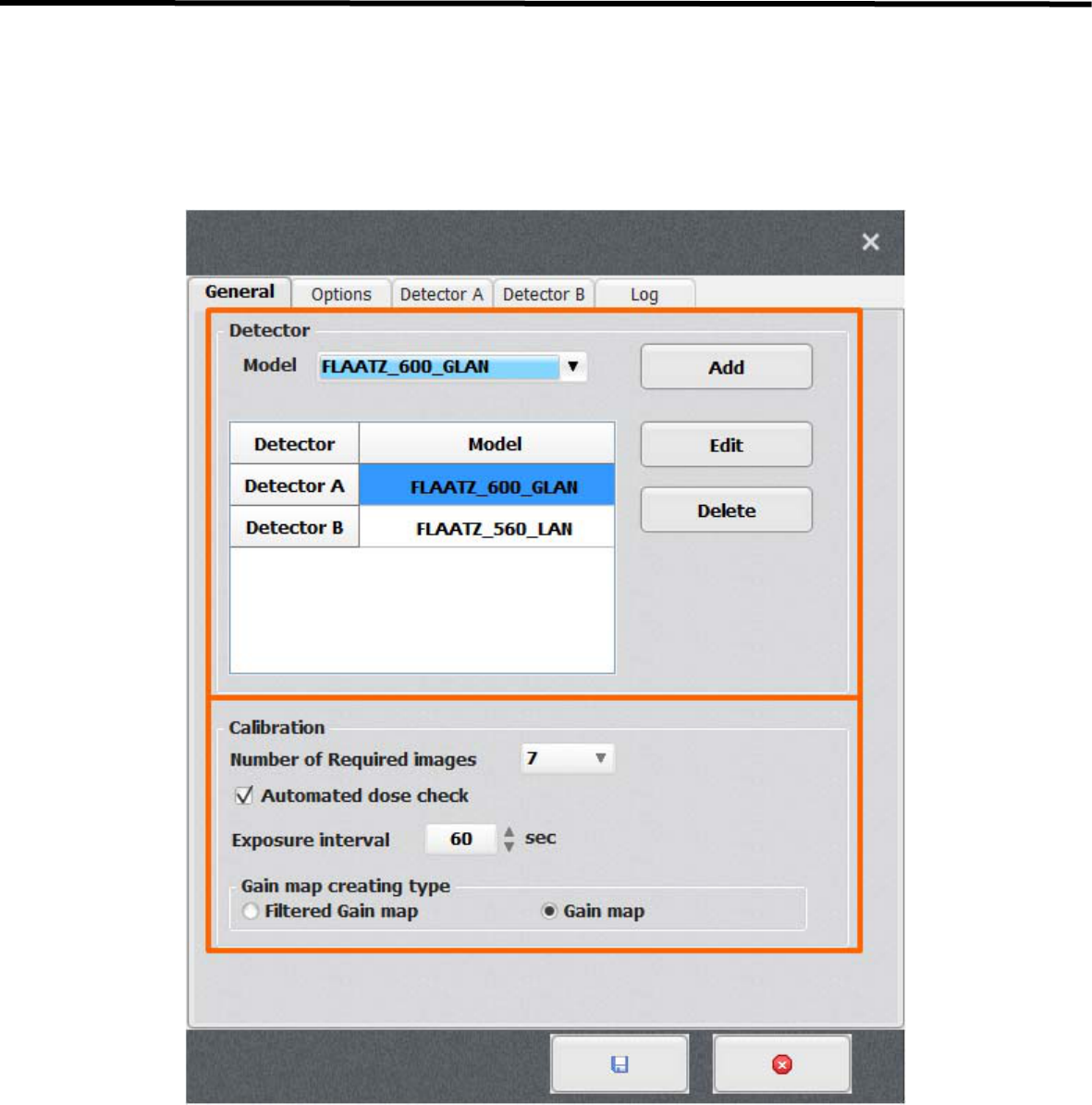
7-12-1 General
Configure the number and type of Detector being utilized.
In addition, Configuration matters required in the process of calibration may be modified.
Figure 7.66. General
EVS 3643 User’s Manual 7. How to Install
10-EVS1MADB001 83
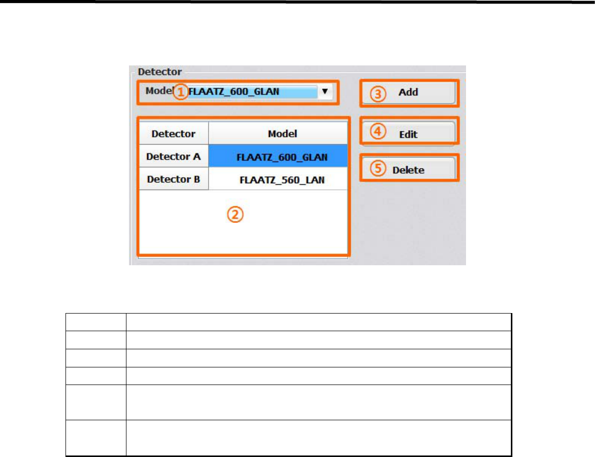
1) Detector Configuration
Figure 7.67. Detector Configuration
Table 7-10. Model Configuration Descriptions
Category Descriptions
① Type of Panel Model which will be added or modified
② Type of Panel added (registered)
③ Adds the Panel Model selected in ①
④ Modifies the Model of the Panel selected in ②
Here, the Model is replaced by the Model selected in ①
⑤ Deletes the most recently registered Panel.
(With disregards to selection, the item at the bottom of the list will be deleted.)
EVS 3643 User’s Manual 7. How to Install
10-EVS1MADB001 84
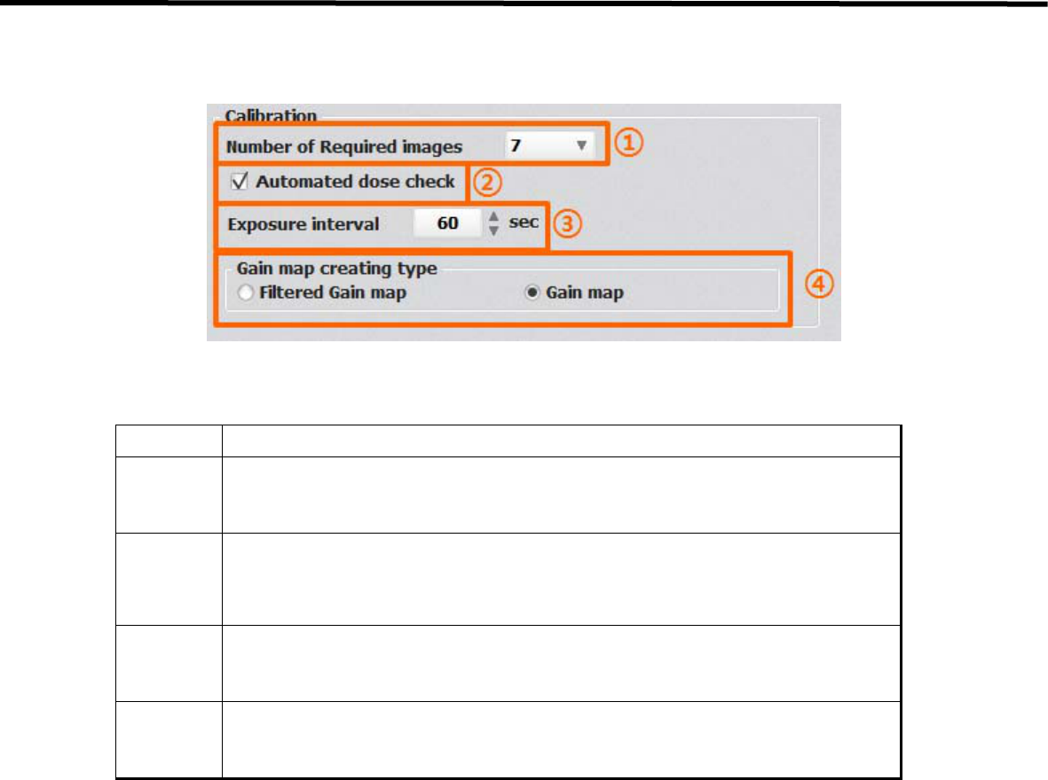
2) Calibration Configuration
Figure7.68. Calibration Configuration
Table 7-5. Calibration Configuration Descriptions
Category Descriptions
① Configures the number of images to be project when performing Gain/Grid
Calibration. The Default value is 7 counts.
②
Checks the X-ray radiation dose when performing Gain Calibration and provides
an option for re-projection if the radiation dose is unfit.
It is recommended for accurate Calibration.
③ Configures the interval between each image projections when performing
Gain/Grid/Panel Calibration. The default value is 60 sec.
④ Select whether to set the Grain Map as Filtered Gain Map or Gain Map.
EVS 3643 User’s Manual 7. How to Install
85
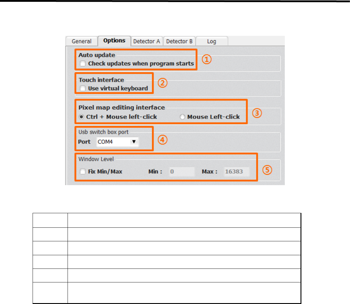
7-12-2 Options
Figure 7.69. Options Configuration
Table 7-6. Options Descriptions
Category Descriptions
① Configures the use of Auto Update function.
② Configures the use of the virtual keyboard for Touch environments.
③ Selects the editing method utilized during the Pixel Map Calibration process.
④ Selects the port connected with USB Switch Box.
⑤ Checks ‘Fix Min / Max’ and inputs Min and Max pixel value to use fixed window
level.
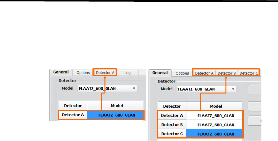
EVS 3643 User’s Manual 7. How to Install
10-EVS1MADB001 86
7-13 Detector
Allows the modification of necessary configuration for each Detector. Number of tabs
corresponding to the number of registered Panels through Configuration – General will be
generated.
Figure 4. Configuration – Changes in the Number of Panel Tabs
The following may be configured through Panel Configurations
Map files save path
Save path of the Map file required for Calibration
Edge cut setting
The boarders of the image
Grid selection
Configurations relevant to the type of Grid and Filter Type being used
F600 Model Configuration
Configurations only for F600
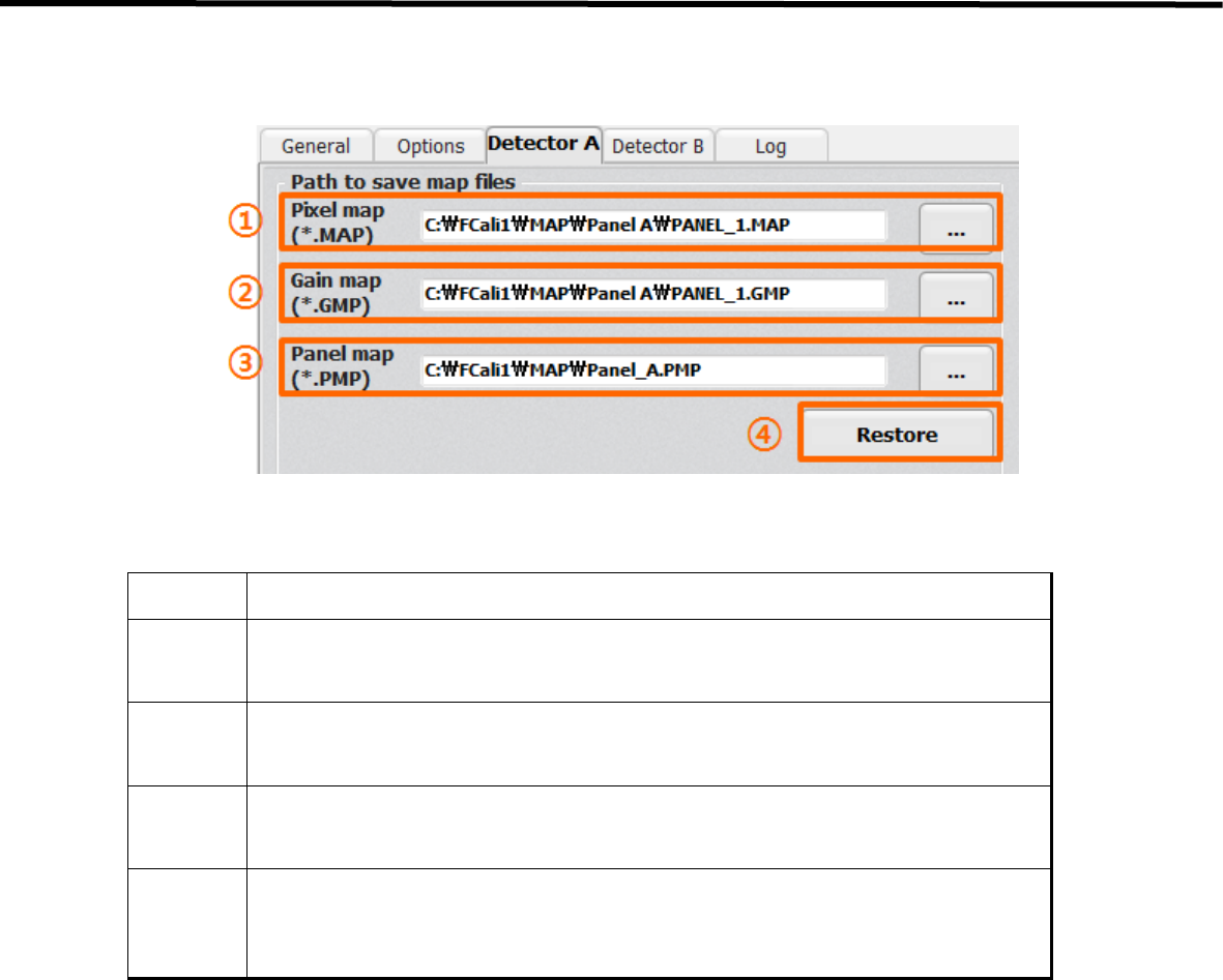
EVS 3643 User’s Manual 7. How to Install
10-EVS1MADB001 87
7-13-1 Map File Path
Figure7.71. Map File Path
Table 7.7. Map File Path Descriptions
Category Descriptions
① Configures the save path of the Pixel Map file.
The File Dialogue may be opened by selecting ‘…’ on the right.
② Configures the save path of the Gain Map file.
The File Dialogue may be opened by selecting ‘…’ on the right.
③ Configures the save path of the Panel Map file.
The File Dialogue may be opened by selecting ‘…’ on the right.
④
Previous Map files are backed-up when Map files are saved multiple times.
Utilized when restoring the Map file with the previous file.
However, restore cannot be processed if a backed-up Map file does not exist.
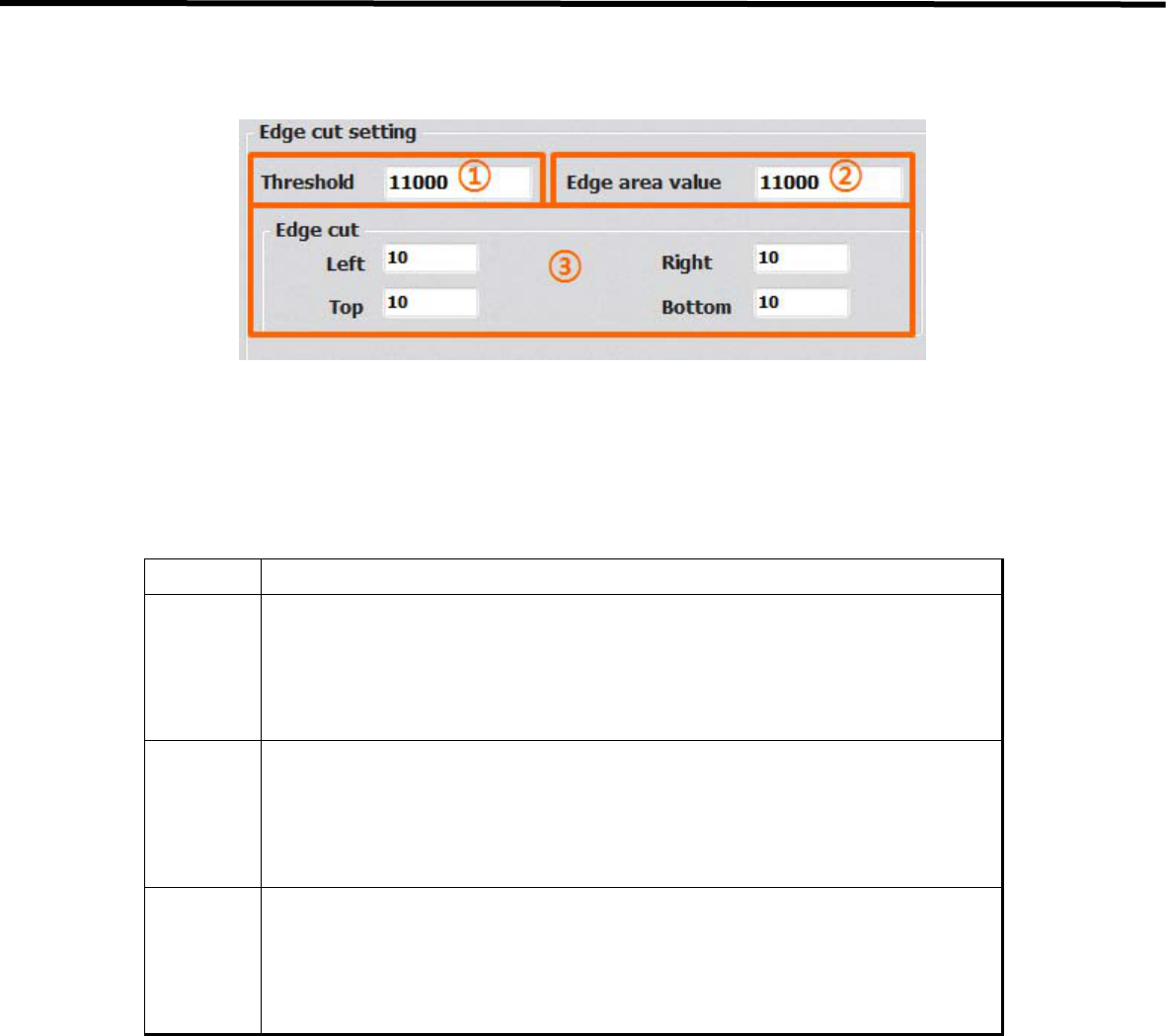
EVS 3643 User’s Manual 7. How to Install
10-EVS1MADB001 88
7-13-2 Edge Cut Setting
Figure 7.72. Edge Cut Setting
Fixed placement of a boarder on the image.
The Pixel value and width may be designated in this configuration.
Table 7.8. Edge Cut Setting Descriptions
Category Descriptions
①
Configures the Threshold Value of the image.
The default is determined by each model.
If the Pixel Value of the image imported from the Detector exceeds 11000, the
values will be automatically adjusted to 11000 if this value is set to 11000.
②
Configures the Pixel Value of the additional boarder which will be placed on
the image.
The default value is 11000.
③ Configures the width of the top, bottom, left and right boarder. Unit is in Pixel.
The Default value is all 10.

EVS 3643 User’s Manual 8. Troubleshooting
10-EVS1MADB001 89
When you encounter problems or error messages in the ECali1 while using this equipment, search the
table below for the problem or error message and try the solutions.
If the problem persists, turn off the detector and consult your sales representative or local DRTECH dealer.
Please refer to the details of the problem or error messages.
Symptom Cause/Error messages in
the EVS Control Software Remedy
Failed to turn on. Power calbe is not attached Attach a power cable with SSU
LINK lamp does not light up The communication circuit is
not secured
Register the detector and make connection
to the ECali1.
In wireless configuration, confirm the following
conditions:
• There is no obstacle between the wireless
module of the detector and the wireless access
points.
• The wireless access point is turned on.
In wired configuration, confirm the following
conditions:
• The detector cable is firmly connected to
the SSU(power box).
• The SSU(power supply) and the AP are firmly
connected via cable.
• The AP is turned on and network
communication is functioning properly.
While the POWER lamp
lights, READY and LINK
lamps flash.
Data transmission error has
occurred.
In wireless configuration, confirm the
following conditions:
• The access point is turned on.
• Wireless communication status is stable
• The access point are firmly connected via
cable.
In wired configuration, confirm the following
conditions:
• The detector cable is firmly connected to
the detector.
• The SSU is turned on.
Exposure preparation error
has occurred. / Error Code:
21
Confirm that the cables with the X-ray
interface unit are connected securely and the
X-ray interface box is turned on.
All the LED lamps flash.
Hardware error has occurred
/Error Code: other than 21 Turn off the detector and turn it on again.
Two LED lamps flash and
Turn off the detector and
turn it on again.
the other flashes slowly.
EVS 3643 User’s Manual 9. Maintenance
10-EVS1MADB001 90
Maintenance and inspection
In order to ensure that the equipment is used safely and normally, be sure to inspect the equipment before
use. If any problem is found during the inspection and cannot be corrected, please contact your sales
representative or local DRTECH dealer.
Daily inspection
WARNING For safety reasons, be sure to turn OFF the power to each piece of
equipment before the following. Otherwise, an electric shock may result.
Cable
1) Ensure that cables are not damaged and cable jackets are not torn.
2) Ensure that the power cord plugs are securely connected to both the equipment AC inlet and the AC
outlet
.
Detector
1) Ensure that there are no loose screws or breaks.
2) Ensure that there is no dust or foreign matter on the external connector.
3) Ensure that there are no breaks or short-circuits in the power supply conector.
After turning on the power
Be sure to start the ECali1 before performing the following inspection.
1) Perform test exposure
.
Monthly inspection
1) Conduct a Performance Test.
2) Regularly conduct a Self-diagnosis. For details, refer to the Setup Guide for the EVS Control Software.
Yearly inspection
1) Perform a Performance Test or Self-diagnosis using a phantom or resolution chart, etc.
Irregular inspection
Calibration
1) Perform Calibration when exposure conditions have changed significantly.
For details, refer to the Setup Guide for the ECali1.
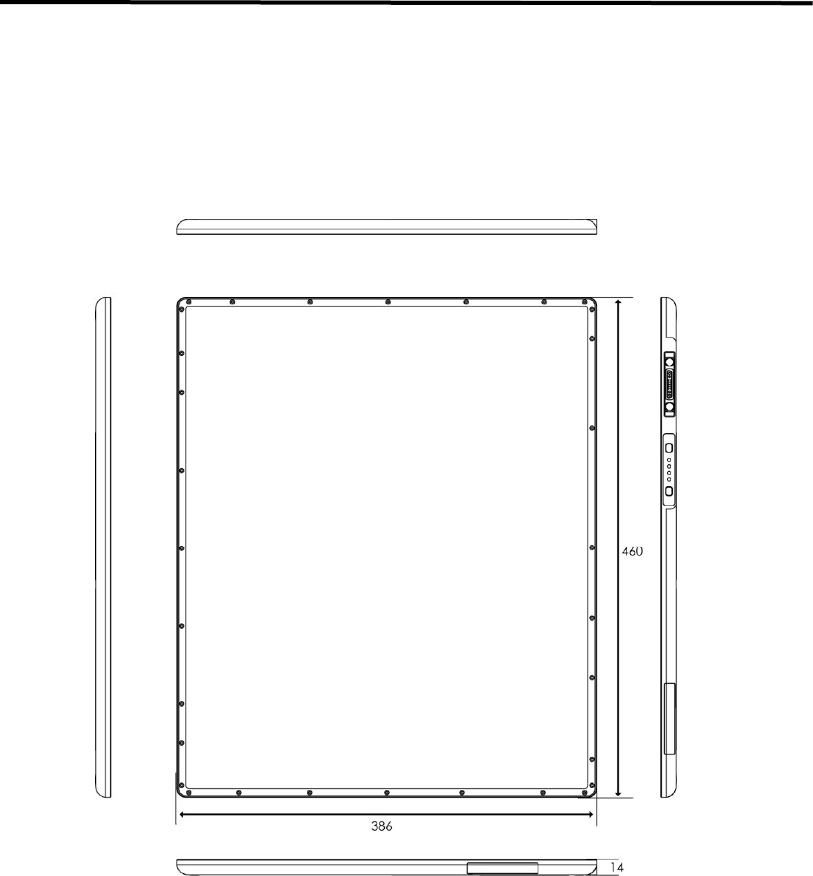
EVS3643 User’s Manual 10. Specifications
10-EVS1MADB001 91
10-1. Main specifications
EVS 3643 X-ray detector
[Dimensional diagram]
(unit mm)
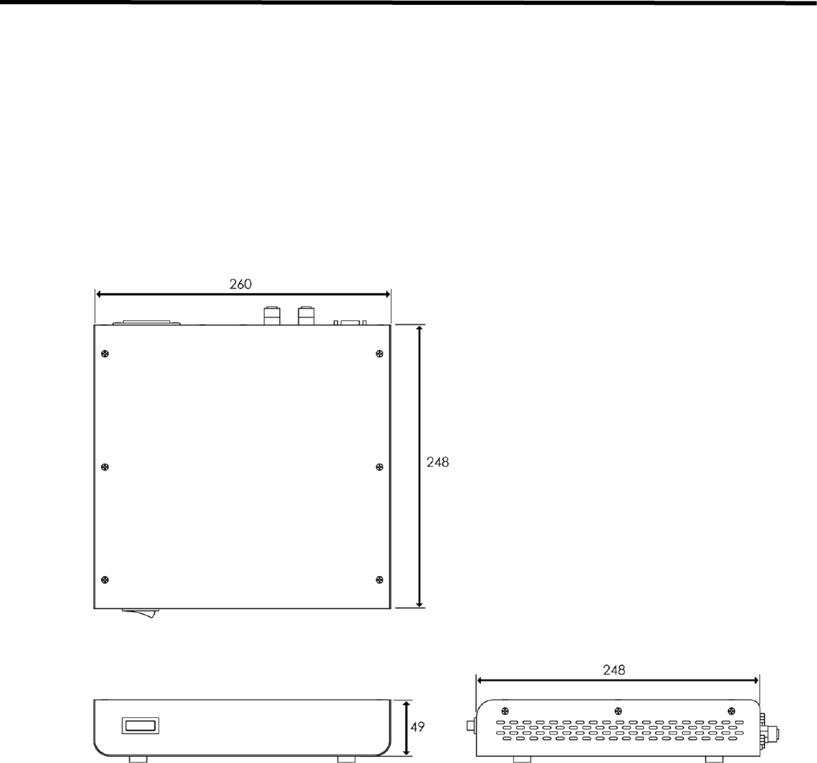
EVS 3643 User’s Manual
10 Specifications
10-EVS1MADB001 92
SSU (System Syncronization Unit)
[Dimensional diagram]
(unit mm)
Rated power supply
Input: 100-240 VAC, 50/60Hz
Output: DC +12 V 8.3A, 75W

EVS 3643 User’s Manual 10. Specifications
10-EVS1MADB001 93
10-2. Charateristics
(1) Typical patient doses
Typical patient doses are equivalent to 500-1000 speed film/screen systems.
(2) Sensitometric characteristics and Dynamic range
EVS 3643 Wireless responds linearly against the exposure range for 500-1000 speed film/screen
where it can depict the clinical information. It means that EVS 3643 fully covers a dynamic range of
0.2-20 μGy at least.
(3) Spatial resolution properties
A typical MTF value at 2 cycle/mm, RQA5 is 0.35.
The level of uncertainty is estimated as less than ±10%.
(4) DQE
A typical DQE value at 2 μGy in 0 lp/mm is 0.6.
The level of uncertainty is estimated as less than ±10%.

EVS 3643 User’s Manual 11. Regulatory information
10-EVS1MADB001 94
The product safety standards that apply to the EVS 3643, which includes the following equipment, are as
followings.
• Detector
• SSU
• Wiring unit (sold separately, optional unit)
11-1. Medical equipment safety standards
Medical equipment classification
Type of protection against electrical
shock Class I ME Equipment
Degree of protection against electrical
shock
Type B Applied Parts
(Applied Part: Detector panel)
Degree of protection against ingress of
water IPX0
Mode of operation Continuous Operation
Flammable anesthetics Not suitable for use in the presence of a flammable anesthetic
mixture with air or with oxygen or nitrous oxide
Product safety standards
USA and Canada
IEC 60601-1:1988
+A1:1991+A2:1995
Medical electrical equipment-Part 1:General requirements for
safety
UL 60601-1 Ed.1.0:2003
CAN/CSA C22.2 No.601.1
IEC 60601-1-1 Ed.2.0:2000 Medical electrical equipment-Part 1-1:Collateral standard:
Safety requirements for medical electrical systems
IEC 60601-1-2 Ed.2.1:2004 Medical electrical equipment-Part 1-2:Collateral
standard: Electromagnetic compatibility-Requirements and tests
IEC 60601-1-3 Ed.1.0:1994
Medical electrical equipment-Part1:Collateral standard: General
requirements for radiation protection in diagnostic X-ray
equipment
IEC 60601-1-4 Ed.1.1:2000 Medical electrical equipment - Part 1-4:Collateral Standard:
Programmable electrical medical systems
IEC 60601-2-32 Ed.1.0:1994 Medical electrical equipment - Part 2: Particular requirements
for the safety of associated equipment of X-ray equipment
ISO 10993-1:2003/-5:1999/
10993-10:2002+A1:2006
Biological evaluation of medical devices
Part 1: Evaluation and testing within a risk management
process
Part 5: Tests for in vitro cytotoxicity
Part 10: Tests for irritation and delayed-type hypersensitivity

EVS 3643 User’s Manual 11. Regulatory information
10-EVS1MADB001 95
European Union
MDD(93/42/EEC) Medical Device Directive
EN ISO 13485:2003+AC:2007 Medical devices -- Quality management systems –
Requirements for regulatory purposes
EN 60601-1:1990+
A1:1993+A2:1995+A13:1996
Medical electrical equipment - Part1:General requirements for
safety
EN 60601-1-1:2001 Medical electrical equipment-Part 1-1:Collateral standard:
Safety requirements for medical electrical systems
EN 60601-1-2:2001 Medical electrical equipment-Part 1-2:Collateral
standard: Electromagnetic compatibility-Requirements and tests
EN 60601-1-3(29.203):1994
Medical electrical equipment-Part 1-3:Collateral standard:
General requirements for radiation protection in diagnostic X-
ray equipment
EN 60601-1-4:1996+A1:1999 Medical electrical equipment - Part 1-4:Collateral
Standard: Programmable electrical medical systems
EN 60601-1-6:2004 Medical electrical equipment - Part 1-6:Collateral Standard:
Usability
EN 60601-2-32:1994 Medical electrical equipment - Part 2: Particular requirements
for the safety of associated equipment of X-ray equipment
EN 62304:2006 Medical device software-Software life cycle processes
EN 62366:2008 Medical device - Application of usability engineering to medical
devices
EN ISO 14971:2007 Medical device - Application of risk management to medical
devices
EN ISO 10993-1:2003/-5:1999/
10993-10:2002+A1:2006
Biological evaluation of medical devices Part 1: Evaluation and
testing within a risk management process
11-2. Medical equipment safety standards
Declaration of conformity
U.S.A. FCC Part 15 Subpart B Class A and Part 15 Subpart C & E
(RF Exposure)
Canada RSS-210
European Union (and EEA) ETSI EN300 328-1,-2 / 300 893-1,-2(Emission)
ETSI EN301 489-1.-17 (Immunity)
Australia AS4268
Singapore IDA TS-14
For U.S.A. and Canada
• FCC/IC compliance
This device complies with Part 15 of the FCC Rules and RSS-Gen of IC Rules.
Operation is subject to the following two conditions:
1. This device may not cause harmful interference.

EVS 3643User’s Manual 5. Operating procedure
10-EVS1MADB001 96
2. This device must accept any interference received, including interference that may cause undesired
operation.
Note: This equipment has been tested and found to comply with the limits for a Class A digital device,
pursuant to part 15 of the FCC Rules. These limits are designed to provide reasonable protection
against harmful interference when the equipment is operated in a commercial environment. This
equipment generates, uses, and can radiate radio frequency energy and, if not installed and used in
accordance with the instruction manual, may cause harmful interference to radio communications.
Operation of this equipment in a residential area is likely to cause harmful interference in which case
the user will be required to correct the interference at his own expense.
FCC WARNING:
Changes or modifications not expressly approved by the party responsible for compliance could void the
user’s authority to operate the equipment.
This transmitter must not be co-located or operated in conjunction with any other
antenna or transmitter.
. 5150~5250 MHz band is restricted to indoor operations only. (for FCC and CE)
FCC ID: RNH-EVS3643
FCC ID: RNH-EVS3643 in the RF module do not use DFS band. *RF modue FCC ID: RYK-WUBR508N.
Host device of the approved module shall be marked with the following item:
Contains Transmitter Module FCC ID: RYK-WUBR508N
Disposal
Disposal of this product in an unlawful manner may have negative effects on health and on the
environment. When disposing of this product, therefore, be absolutely sure to follow the
procedure which is in conformity with the laws and regulations applicable in your area.
The expected life span of EVS 3643 system is about 3 years.

EVS 3643 User’s Manual 11. Regulatory information
10-EVS1MADB001 97
For European Union (and EEA)
English Hereby, DRTECH Inc., declares that this EVS-3643 Wireless is in compliance with the
essential requirements and other relevant provisions of Directive 1999/5/EC.
Česky DRTECH Inc. tímto prohlašuje, že tento EVS 3643 Wireless je ve shodě se základními
požadavky a dalšími příslušnými ustanoveními směrnice 1999/5/ES.
Dansk Undertegnede DRTECH Inc. erklærer herved, at følgende udstyr EVS 3643 Wireless
overholder de væsentlige krav og øvrige relevante krav i direktiv 1999/5/EF.
Deutsch
Hiermit erklärt DRTECH Inc., dass sich das Gerät EVS 3643 Wireless in Übereinstimmung mit
den grundlegenden Anforderungen und den übrigen einschlägigen Bestimmungen der
Richtlinie 1999/5/EG befindet.
Eesti Käesolevaga kinnitab DRTECH Inc. seadme EVS 3643 Wireless vastavust direktiivi
1999/5/EÜ põhinõuetele ja nimetatud direktiivist tulenevatele teistele asjakohastele sätetele.
Español
Por medio de la presente DRTECH Inc. declara que el EVS 3643 Wireless cumple con los
requisitos esenciales y cualesquiera otras disposiciones aplicables o exigibles de la Directiva
1999/5/CE.
Ελληνική
ΜΕ ΤΗΝ ΠΑΡΥΣΑ DRTECH Inc. ∆ΗΛΩΝΕΙ ΤΙ EVS 3643 Wireless ΣΥΜΜΡΦΩΝΕΤΑΙ
ΠΡΣ ΤΙΣ ΥΣΙΩ∆ΕΙΣ ΑΠΑΙΤΗΣΕΙΣ ΚΑΙ ΤΙΣ ΛΙΠΕΣ ΣΕΤΙΚΕΣ ∆ΙΑΤΑΕΙΣ ΤΗΣ ∆ΗΓΙΑΣ
1999/5/ΕΚ.
Français Par la présente DRTECH Inc. déclare que l’appareil EVS 3643 Wireless est conforme aux
exigences essentielles et aux autres dispositions pertinentes de la directive 1999/5/CE.
Italiano Con la presente DRTECH Inc. dichiara che questo EVS 3643 Wireless è conforme ai requisiti
essenziali ed alle altre disposizioni pertinenti stabilite dalla direttiva 1999/5/CE.
Latviski Ar šo DRTECH Inc. deklare, ka EVS 3643 Wireless atbilst Direktivas 1999/5/EK butiskajam
prasibam un citiem ar to saistitajiem noteikumiem.
Lietuviu Šiuo DRTECH Inc. deklaruoja, kad šis EVS 3643 Wireless atitinka esminius reikalavimus ir
kitas 1999/5/EB Direktyvos nuostatas.
Nederlan
ds
Hierbij verklaart DRTECH Inc. dat het toestel EVS 3643 Wireless in overeenstemming is met
de essentiële eisen en de andere relevante bepalingen van richtlijn 1999/5/EG.
Malti Hawnhekk, DRTECH Inc., jiddikjara li dan EVS 3643 Wireless jikkonforma malhtigijiet
essenzjali u ma provvedimenti ohrajn relevanti li hemm fid-Dirrettiva 1999/5/EC.
Magyar Alulírott, DRTECH Inc. nyilatkozom, hogy a EVS 3643 Wireless megfelel a vonatkozó alapvetõ
követelményeknek és az 1999/5/EC irányelv egyéb elõírásainak.
Polski Niniejszym DRTECH Inc. oswiadcza, ze EVS 3643 Wireless jest zgodny z zasadniczymi
wymogami oraz pozostalymi stosownymi postanowieniami Dyrektywy 1999/5/EC.
Portuguê
s
DRTECH Inc. declara que este EVS 3643 Wireless está conforme com os requisitos
essenciais e outras disposições da Directiva 1999/5/CE.
Slovensk
o
DRTECH Inc. izjavlja, da je ta EVS 3643 Wireless v skladu z bistvenimi zahtevami in ostalimi
relevantnimi dolocili direktive 1999/5/ES.
Slovensk
y
DRTECH Inc. týmto vyhlasuje, že [typ zariadenia] splna základné požiadavky a všetky
príslušné ustanovenia Smernice 1999/5/ES.
Suomi DRTECH Inc. vakuuttaa täten että EVS 3643 Wireless tyyppinen laite on direktiivin 1999/5/EY
oleellisten vaatimusten ja sitä koskevien direktiivin muiden ehtojen mukainen.
Svenska
Härmed intygar DRTECH Inc. att denna EVS 3643 Wireless står I överensstämmelse med de
väsentliga egenskapskrav och övriga relevant bestämmelser som framgår av direktiv
1999/5/EG.
Íslenska Hér með lýsir DRTECH Inc. yfir því að EVS 3643 Wireless er í samræmi við grunnkröfur og
aðrar kröfur, sem gerðar eru í tilskipun 1999/5/EC.
Norsk DRTECH Inc. erklærer herved at utstyret EVS-3643 Wireless er i samsvar med de
grunnleggende krav og øvrige relevante krav i direktiv 1999/5/EF.

EVS 3643 User’s Manual 11. Regulatory information
10-EVS1MADB001 98
AT BE BG CY CZ DK EE FI
FR* DE GR HU IE IT LV LT
LU MT NL PL PT RO SK SI
ES SE GB IS LI NO CH
* In France, outdoor use of this equipment is prohibited.
For Singapore
Complies with IDA Standards N1624-10
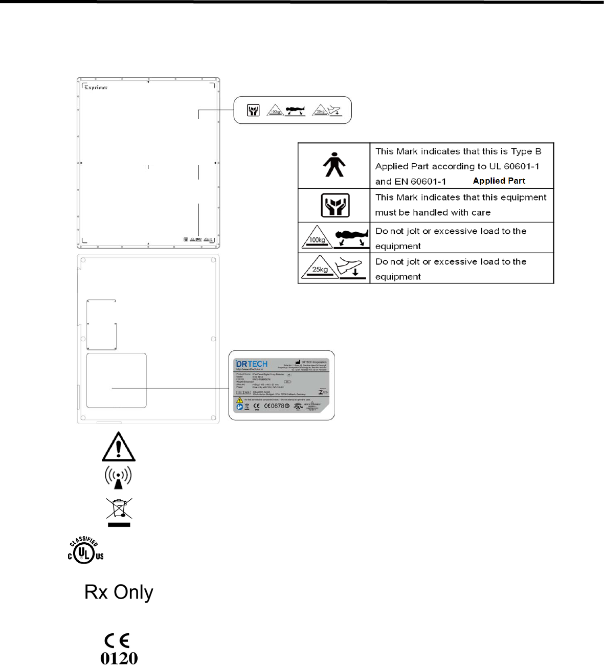
EVS 3643 User’s Manual
11. Regulatory information
10-EVS1MADB001 99
Applied Part
11-3. Medical equipment safety standards
The EVS 3643 detector and other components have labels and markings on them.
Their contents and locations are indicated below.
Caution:
Do not jolt or apply excessive load.
Non-ionized radiation
The Waste Electrical and Electronic Equipment Regulations indicates separate
collection for
electrical and electronic equipment.
MEDICAL
EQUIPMENTUL60601-1
CAN/CSA C22.2 No.601.1
41C4
Certification mark that indicates the product complies with UL 60601-1
and CAN/CSA C22.2 No.601.1, that specifies protection against fire, electric
shock, and mechanical hazards.
For U.S.A
Caution:
Federal law restricts this device to sale by or on the order of a licensed
practitioner.
For European Union (EEC Countries)
Hereby, DRTECH Inc., declares that this EVS-3643 Wireless is in compliance
with the essential equirements and other relevant provisions of Directive
1999/5/EC and 93/42/EEC. “0120”
shows the notified body number for MDD.
MANUFACTUED:
Year and Month of production
(S/N)
Serial number in six digits
Detector Panel
Active area
(430 x430 mm)
Detector Panel
Active area
(430 x430 mm)
Applied Part
Detector Case
(460 x 460 mm)

EVS 3643 User’s Manual 11. Regulatory information
10-EVS1MADB001 100
This mark shows compliance of the equipment with Directive 93/42/EEC
Protective Earth (Ground)
Direct Current
Alternating Current
Equipotentially.
Attention, Consult accompanying documents.
Power Off.
Power On
Read and understand all instructions and warning labels in the product
documentation before using the equipment.
Keep manual for future reference
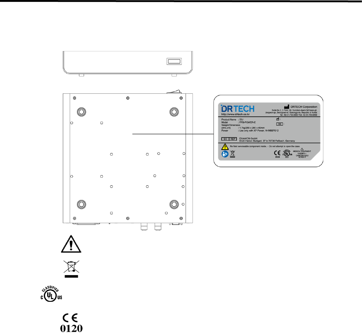
EVS 3643 User’s Manual
11. Regulatory information
10-EVS1MADB001 101
Other components of the EVS 3643 system
SSU
Caution:
Do not jolt or apply excessive load.
The Waste Electrical and Electronic Equipment Regulations indicates separate
collection for
electrical and electronic equipment.
MEDICAL
EQUIPMENTUL60601-1
CAN/CSA C22.2 No.601.1
41C4
Certification mark that indicates the product complies with UL 60601-1
and CAN/CSA C22.2 No.601.1, that specifies protection against fire, electric
shock, and mechanical hazards.
For European Union (EEC Countries)
Hereby, DRTECH Inc., declares that this EVS 3643 Wireless is in compliance
with the essential equirements and other relevant provisions of Directive
1999/5/EC and 93/42/EEC. “0120”
shows the notified body number for MDD.
MANUFACTUED:
Year and Month of production
(S/N)
Serial number in six digits

EVS 3643 User’s Manual 11. Regulatory information
10-EVS1MADB001 102
Protective Earth (Ground)
Direct Current
Alternating Current
Equipotentially.
Attention, Consult accompanying documents.
Power Off.
Power On
Read and understand all instructions and warning labels in the product
documentation before using the equipment.
Keep manual for future reference

EVS 3643 User’s Manual 11. Regulatory information
10-EVS1MADB001 103
11-4. Guidance and manufacturer’s declaration for EMC
Electromagnetic emissions
The EVS 3643 Wireless is intended for use in the electromagnetic environment specified below.
The user of the EVS 3643 Wireless should assure that it is used in such an environment.
Emission Test Compliance Electromagnetic Environment - Guidance
RF emissions
CISPR11 GROUP 1
The EVS 3643 Wireless uses RF energy only for its internal
function.
Therefore, its RF emissions are very low and are not likely to
cause any interference in nearby electromagnetic equipment.
RF emissions
CISPR11 Class A
The EVS-3643 Wireless is suitable for use in all
establishments other than domestic and those directly
connected to the public low-voltage power supply network
that supplies buildings used for domestic purposes.
Harmonic emissions
IEC 61000-3-2 Class A
Voltage fluctuations/
flicker emissions
IEC 61000-3-3
*1
1: Applies to regions where the rated voltage is 220 V or higher. Not applicable to regions where the rated
voltage is less than 220 V.
Electromagnetic immunity
The EVS 3643 Wireless is intended for use in the electromagnetic environment specified below.
The user of the EVS 3643 Wireless should assure that it is used in such an environment.
Immunity Test IEC 60601 Test
Level Compliance Level Electromagnetic
Environment – Guidance
Electrostatic discharge
(ESD)
IEC 61000-4-2
±(2, 4, 6) kV contact
±(2, 4, 8) kV air
±(2, 4, 6) kV contact
±(2, 4, 8) kV air
Floors should be wood,
concrete or ceramic tile. If
floors are covered with
synthetic material, the relative
humidity should be at least
30%.
Electrical fast transient/
burst
IEC 61000-4-4
±2 kV for power
supply lines
±1 kV for input/output
lines
±2 kV for power
supply lines
±1 kV for input/output
lines
Mains power quality should be
that of a typical commercial or
hospital environment.
Surge
IEC 61000-4-5
±1 kV differential
mode
±2 kV common mode
±1 kV differential
mode
±2 kV common mode
Mains power quality should be
that of a typical commercial or
hospital environment
NOTE: UT is the a.c. mains voltage prior to application of the test level.

EVS 3643 User’s Manual 11. Regulatory information
10-EVS1MADB001 104
Immunity Test IEC 60601 Test
Level Compliance Level Electromagnetic
Environment – Guidance
Voltage dips, short
interruptions and voltage
variations on power
supply input lines
IEC 61000-4-11
<5% UT
(>95% dip in UT) for
0.5 cycle.
40% UT
(60% dip in UT) for
5 cycles
70% UT
(30% dip in UT) for
25 cycles
<5% UT
(>95% dip in UT) for
5 sec.
<5% UT
(>95% dip in UT) for
0.5 cycle.
40% UT
(60% dip in UT) for
5 cycles
70% UT
(30% dip in UT) for
25 cycles
<5% UT
(>95% dip in UT) for
5 sec.
Mains power quality should be
that of a typical commercial or
hospital environment. If the user
of the EVS 3643 Wireless requires
continued operation during power
mains interruptions, it is
recommended that the EVS 3643
Wireless be powered from an
uninterruptible power supply
Power frequency
(50/60Hz) magnetic field
IEC 61000-4-8
3 A/m 3 A/m
Power frequency magnetic fields
should be at levels characteristic of a
typical location in a typical
commercial or hospital environment.
Conducted RF
IEC 61000-4-6
Radiated RF
IEC 61000-4-3
3 Vrms
150 kHz to 80 MHz
3 V/m
80 MHz to 2.5 GHz
3 Vrms
3 V/m
The RF communications equipment
should be used no closer to any
part of the EVS 3643 Wireless,
including cables, than the
recommended separation distance
calculated from the equation
applicable to the frequency of the
transmitter.
Recommended separations distance
d=1.2√P
d=1.2 √P 80 MHz to 800 MHz
d=2.3 √P 800 MHz to 2.5 GHz
where P is the maximum output
power rating of the transmitter in
watts (W) according to the transmitter
manufacturer and d is the
recommended separation distance in
meters (m).
Field strengths from fixed RF
transmitters, as determined by an
electromagnetic site survey a,
should be less than the
compliance level in each
frequency range b.
Interference may occur in the
vicinity of equipment marked with
the following symbol:
NOTE 1: At 80 MHz and 800 MHz, the higher frequency range applies.
NOTE 2: These guidelines may not apply in all situations. Electromagnetic propagation is affected by absorption
and reflections from structures, object and people.

EVS3643 User’s Manual 11. Regulatory information
10-EVS1MADB001 105
a Field strengths from fixed transmitters, such as base stations for radio (cellular/cordless) telephones and land
mobile radios, amateur radio, AM and FM radio broadcast and TV broadcast cannot be predicted theoretically
with accuracy. To assess the electromagnetic environment due to fixed RF transmitters, an electromagnetic
site survey should be considered. If the measured field strength in the location in which the EVS 3643
Wireless is used exceeds the applicable RF compliance level above, the EVS 3643 Wireless should be
observed to verify normal operation. If abnormal performance is observed, additional measures may be
necessary, such as reorienting or relocating the EVS 3643 Wireless.
b Over the frequency range 150 kHz to 80 MHz, field strengths should be less than 3 V/m.

EVS3643 User’s Manual 12. Warranty
10-EVS1MADB001 106
DRTECH Inc. warrants that this product will be free from defects in materials and workmanship for a period of
twelve (12) months from the date of delivery. If any such product proves defective during this warranty period,
DRTECH Inc. at its option, either will repair the defective product without charge for parts and labor, or will
provide a replacement in exchange for the defective product. In order to obtain service under this warranty,
Customer must notify DRTECH Inc. of the defect before the expiration of the warranty period and make suitable
arrangements for the performance of service. Customer shall be responsible for packaging and shipping the
defective product to the service center designated by DRTECH Inc. with shipping charges prepaid. DRTECH Inc.
shall pay for the return of the product to customer if the shipment is to a location within the country in which the
DRTECH Inc. designated service center is located. Customer shall be responsible for paying all shipping
charges, duties, taxes, and any other charges for products returned to any other locations.
This warranty shall not apply to any defect, failure, or damage caused by improper or inadequate maintenance
and care. DRTECH Inc. shall not be obligated to furnish service under this warranty to repair damage resulting
from attempts by personnel other than DRTECH Inc. or its representatives to install, repair, or service this
product, to repair damage resulting from improper use or connection to incompatible equipment or power source;
or to service a product that has been modified or integrated with other products when the effect of such
modification or integration increases the time or difficulty of servicing the product.
THIS WARRANTY IS GIVEN BY DRTECH Inc. WITH RESPECT TO THIS PRODUCT IN LIEU OF ANY OTHER
WARRANTIES, EXPRESS OR IMPLIED. DRTECH Inc. AND ITS VENDOR DISCLAIM ANY IMPLIED
WARRANTIES OF MERCHANTABLILITY OR FITNESS FOR A PARTICULAR PURPOSE. DRTECH Inc.
RESPONSIBILITY TO REPAIR OR REPLACE DEFECTIVE PRODUCTS IS THE SOLE REMEDY PROVIDED
TO THE CUSTOMER FOR BREACH OF THIS WARRANTY. DRTECH AND ITS VENDORS WILL NOT BE
LIABLE FOR ANY INDIRECT, SPECIAL, INCIDENTAL, OR CONSEQUENTIAL DAMAGES IRRESPECTIVE OF
WHETHER VIEWORKS CO., LTD OR THE VENDOR HAS ADVANCE NOTICE OF THE POSSIBILITY OF
SUCH DAMAGES.
There are no warranties which extend beyond the description mentioned in this document.

EVS3643 User’s Manual
10-EVS1MADB001 113
Revision History
Revision Date Descriptions
1.0 Feb. 11. 2014 Initial Release

EVS 3643User’s Manual 5. Operating procedure
10-EVS1MADB001 96
DRTECH
DRTECH Inc.
Suite No.2 3 Floor, 29
Dunchon-daero541beon -gil,
Jungwon-gu, Seongnam-si, Gyeonggi-do, Republic of Korea
Web Site : http://www.drtech.co.kr
Customer Support Team
E-mail : drtech@drtech.co.kr
Tel : +82 31 730 6805 / Fax : +82 31 730 6899
European representative: