DTC Communications DSS950TX User Manual Operators Manual
DTC Communications Inc. Operators Manual
Operators Manual

DOCUMENT NUMBER: OP1920052 REV. B
DESCRIPTION: DSS-950-TX
500mW Digital Spread Spectrum
Audio Surveillance Transmitter
USER’S MANUAL
ECO NUMBER: 2130
Page 0 of 4
Date: 11/23/1999
Orig:_____________
SIGN OFF DATE: mm/dd/yy
Proj Eng._________________
Mfg Mgr. _________________
Documentation ____________
Eng. Mgr._________________
Purchasing _______________

OP1920052 REV B DTC COMMUNICATIONS INC 11/23/1999 1 of 4
DSS-950-TX
500 mW Digital Spread Spectrum
Audio Surveillance Transmitter
User’s Manual
November 1999
Document OP1920052
DTC COMMUNICATIONS, Inc.
75 Northeastern Blvd.
Nashua, NH 03062
OP1920052 REV B DTC COMMUNICATIONS INC 11/23/1999 2 of 4
Description
The DSS-950TX is a 900 MHz, low power, spread spectrum audio surveillance transmitter used
for law enforcement applications. The transmitter employs digital modulation with direct sequence
spread spectrum on one of three factory-selected channels in the 902-928 MHz range.
The DSS-950TX has a power output of 500mW to an integral patch antenna built into the
housing, which meets the technical and safety requirements of FCC Part 15.203. This device is
compatible with the DTC Communications DSS-900-KT Audio Surveillance System. Range will
be approximately 2 to 3 times that of a 50 mW unit.
Two microphone modes are supported, internal and external. The microphone audio is processed
by an amplifier equipped with an automatic gain control (AGC) which may be turned ON or OFF
with an external switch. Microphone audio is secure; processed digitally with a continuously
variable slope delta-modulation (CVSD) speech coder at a rate of 32 kbps.
The DSS-950TX is a portable device; DC powered by three AA batteries, which supply a nominal
4.5 VDC. A step-up switcher is employed, which maintains the full half-Watt of output power over
the entire life of the batteries. Alkaline batteries will provide more than two hours of operating life
and Lithium-Ion AA’s will provide more than four hours.
The DSS-950-M is a flying lead module based on the same device, but is made roughly half the
size. This module operates from an external 10 – 32 VDC via stripped and tinned leads and is
designed for use with larger battery packs and vehicular power. The antenna is also integral to
this unit.
Using the Transmitter
Keep in mind that the TX patch antenna must be facing away from the agent’s body to work
properly. The patch antenna is housed under a black plastic-like cover at the top of the unit.
There is no external antenna on this unit. This is a high current drain device (500 mA); always
replace the batteries before using the unit.
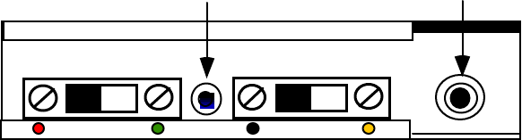
• He internal top-fire mike is located between the two slide switches. It is active unless an
external mike is plugged into the locking subminiature connector. Two microphones are
supplied with the DSS-9500; they differ only in cable length and color. External microphones
may be extended up to 100 feet from the transmitter.
Power
Off On AGC
Off On
Internal
Microphone External
Microphone
ANTENNA SIDE (AWAY FROM BODY)
Figure 1 TX Control Panel
OP1920052 REV B DTC COMMUNICATIONS INC 11/23/1999 3 of 4
Using the Transmitter (Cont.)
CAUTION:
ALWAYS MAKE SURE THAT THE PLASTIC ANTENNA COVER IS FACING OUTWARDS;
AWAY FROM THE TORSO, IN ORDER TO MAXIMIZE RANGE AND MINIMIZE RADIO
FREQUENCY ABSORBPTION INTO THE BODY. THIS DEVICE HAS BEEN TESTED AND
HAS BEEN FOUND TO BE WITHIN SAFE LEVELS FOR LOCALIZED SPECIFIC
ABSORPTION FOR UNCONTROLLED ENVIRONMENT/GENERAL POPULATION
EXPOSURE WHEN USED PROPERLY.
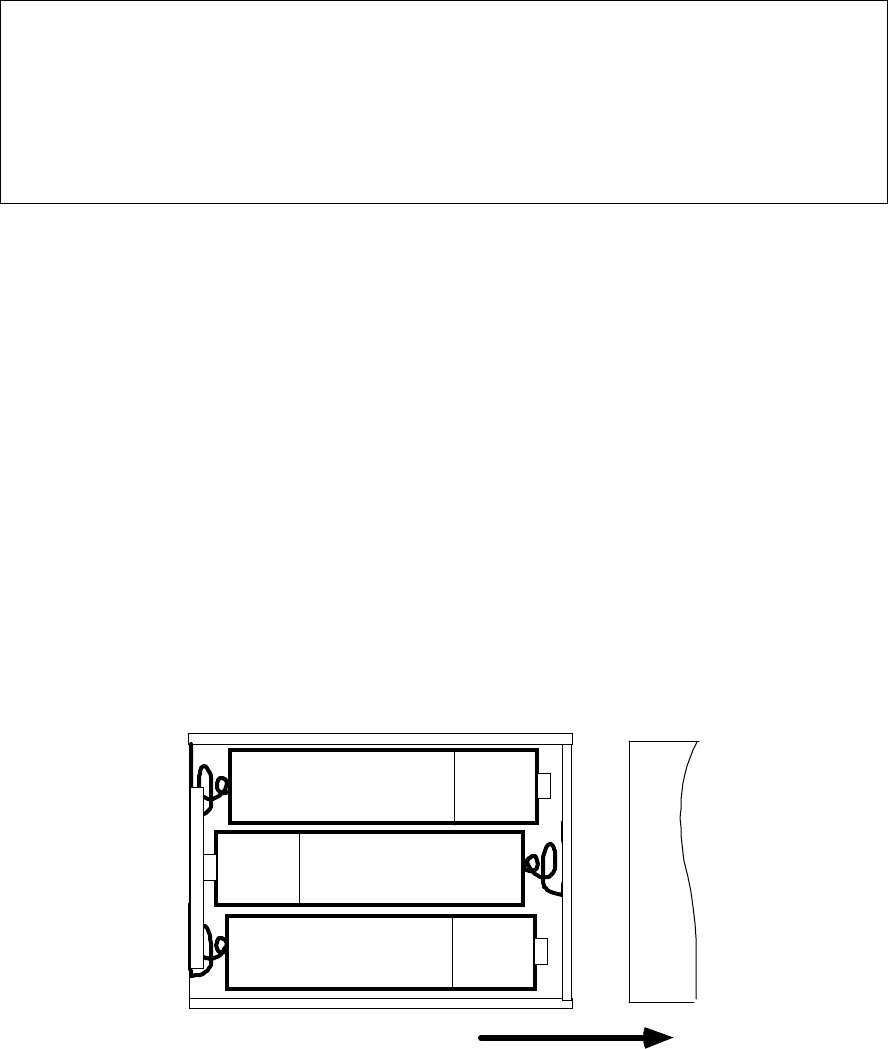
1. Start the surveillance session with fresh AA batteries. Duracell™ MN1500 or Energizer™ E91
LR6 AM3 or Ultra™ batteries are all good choices for Alkalines. The Energizer L91 Lithium
will provide better than double the life of the best Alkalines. Slide the battery door open to
insert the batteries. (Figure 2).
2. The TX unit is labeled with its frequency.
3. Set the CHANNEL SELECT on the RECEIVER to 1 for 905.5 MHz, 2 for 915 MHz and 3 for
924.5 MHz. Always check that the receiver is set on your frequency. At this power level, the
transmitter may bleed into an adjacent channel and cause a false indication when the
transmitter is very close to the receiver.
4. Turn the TX ON (Green Dot) using the slide switch at the top of the unit.
5. Set the AGC switch to ON (Yellow Dot). This provides the optimum audio at the RX. Turn the
AGC OFF (Black) if a loud, interfering noise, such as a jukebox, is near the microphone.
6. Mount the transmitter as high on the torso as possible, to maximize range and performance,
especially when the agent may enter a vehicle.
SLIDE COVER
+
+
+
Figure 2 Battery Door
OP1920052 REV B DTC COMMUNICATIONS INC 11/23/1999 4 of 4
Specifications
Input: FET-Electret Mic. (internal and external with 24“ cable-auto. switching)
Controls: Power ON/OFF, AGC ON/OFF
Antenna: Linear Patch
Power Output: 500 mW
Audio Coder Rate: 32 kbps
AGC Range 45 dB
Modulation: Direct Sequence Spread Spectrum
Chip Rate: 704 kilochips per second
Processing gain: Greater than 10 dB
Spreading Code Proprietary 37-chip code (Factory fixed)
Spurious Radiation Greater than -45 dBc:
Frequencies: A = 905.5 MHz; B = 915.0 MHz; C = 924.5 MHz
(3 Channel capability; single channel factory selected)
Battery: 4.5 VDC with 3 AA batteries
Battery Life: 2 Hours Minimum Alkaline, 4 Hours minimum Lithium
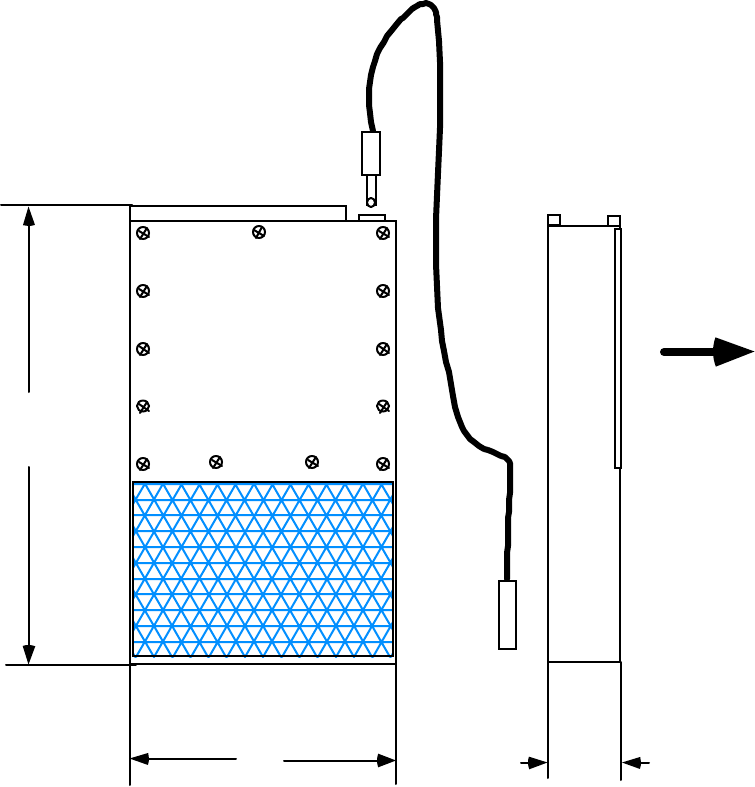
Dimensions: 2.5” X 4.45” X 0.67”
Weight: 10 oz including external microphone and batteries
0.67
ANTENNA
SIGNAL RADIATION
BAT DOOR
4.45
2.5
BODY SIDE
Copyright © 1999 DTC Communications Inc.