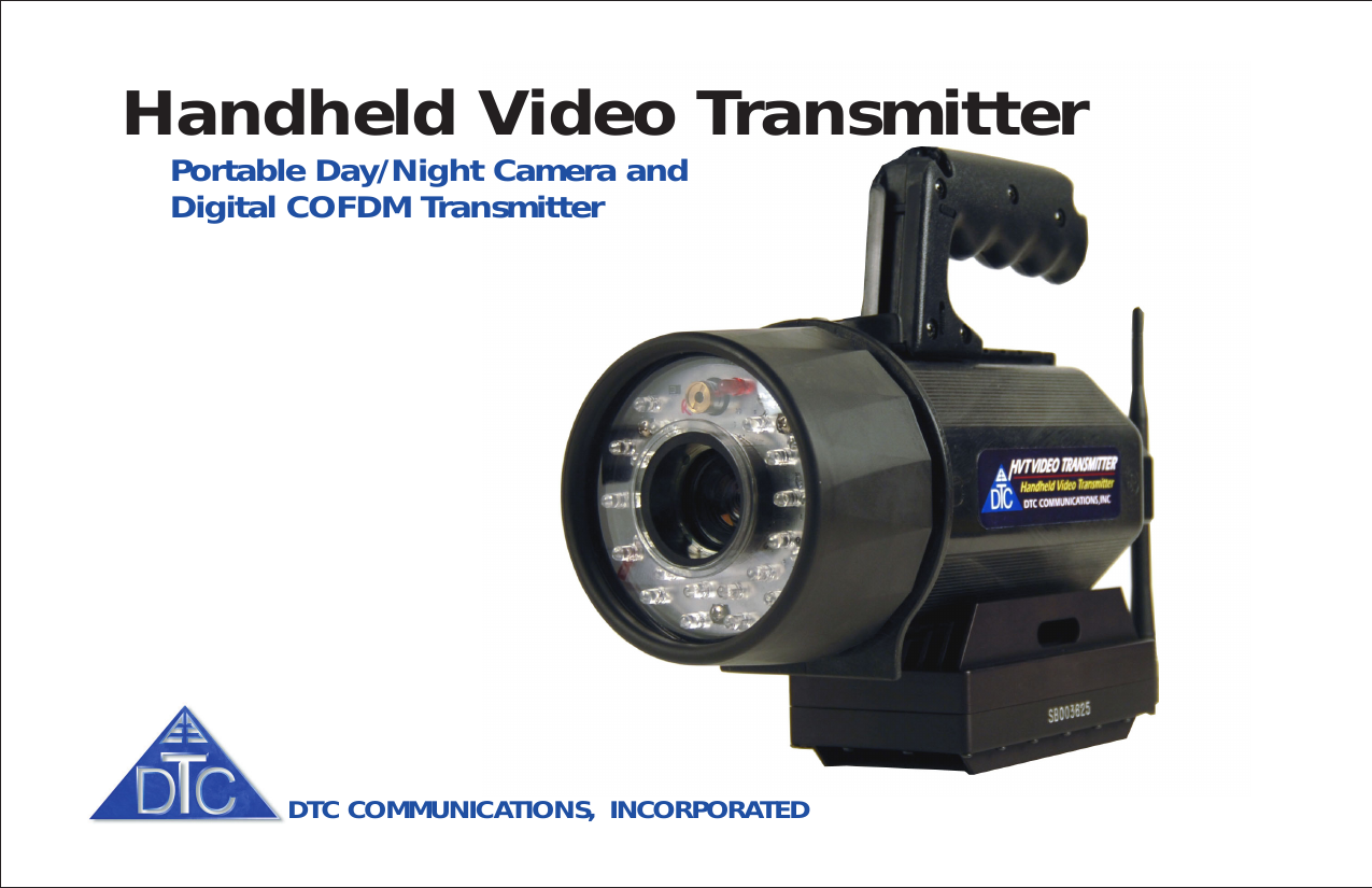
DTC Communications HVT250-S Handheld Video Transmitter User Manual HVT Manual Rev2b
DTC Communications Inc. Handheld Video Transmitter HVT Manual Rev2b
UserManual.wiki
>
DTC Communications
>
HVT250 S User Manual
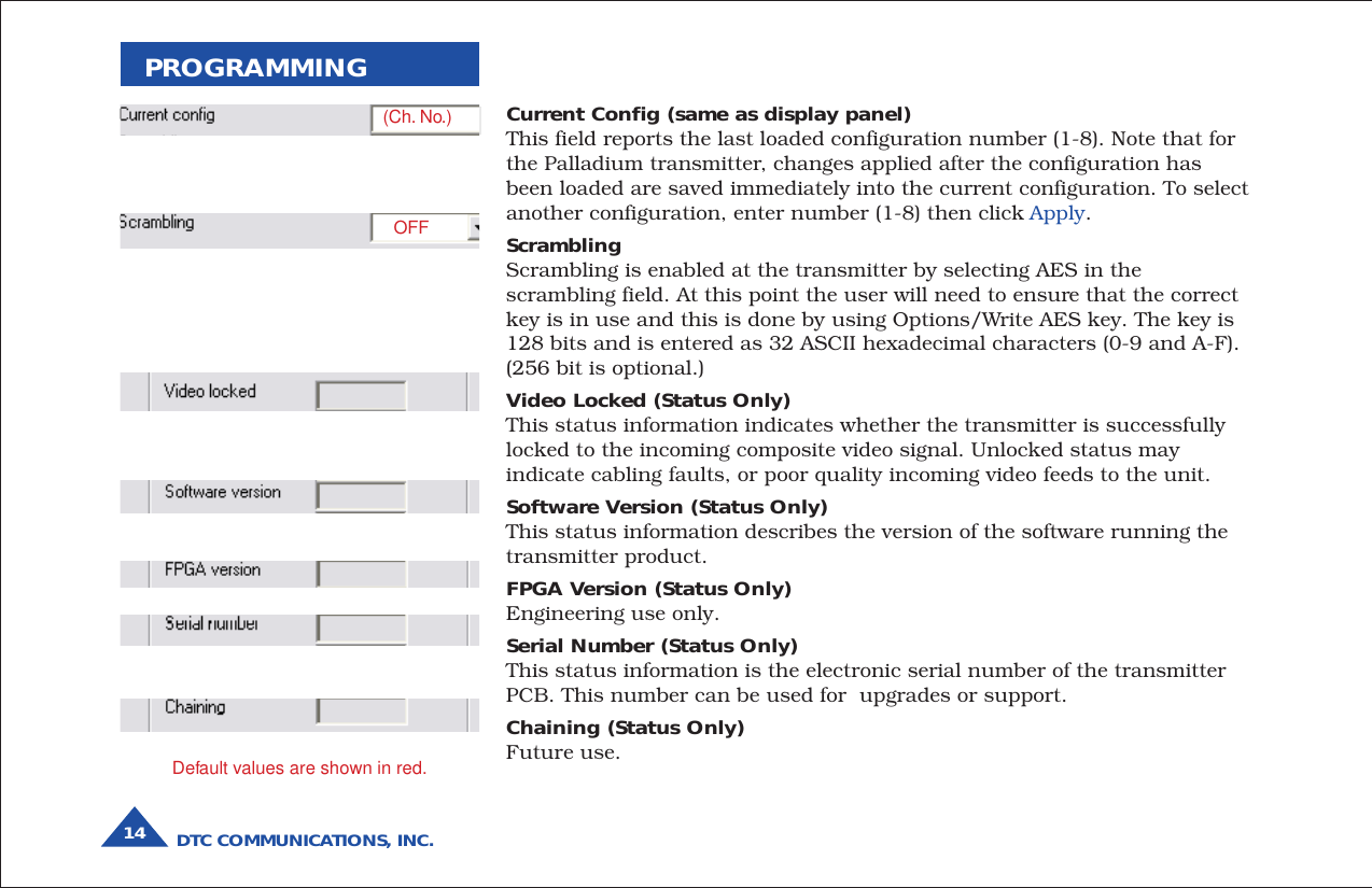
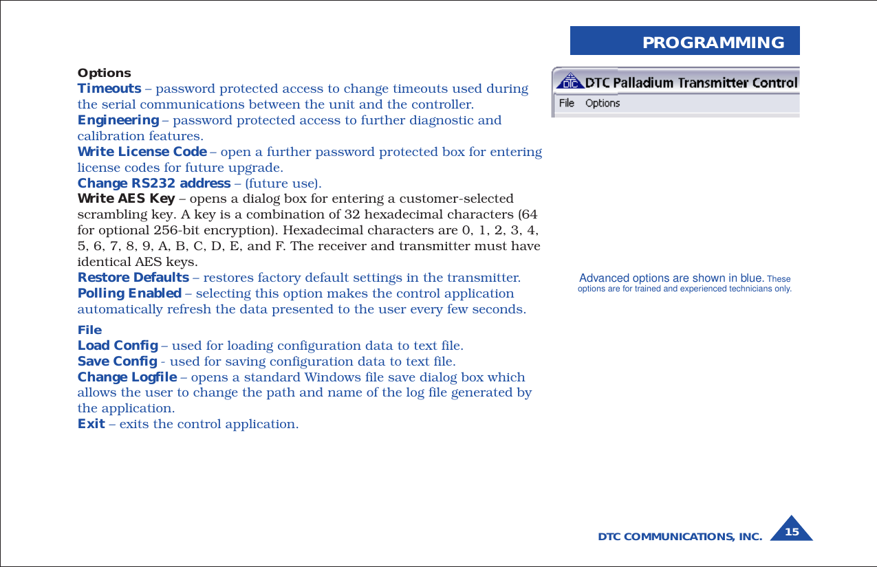
Users Manual
Navigation menu
Upload a User Manual
Namespaces
Wiki Guide
HTML
PDF
Info
Views
User Manual
Discussion / Help
Navigation