DTC Communications PD2TX1000S COFDM TX User Manual Revised September 2011
DTC Communications Inc. COFDM TX Users Manual Revised September 2011
Users Manual Revised September 2011
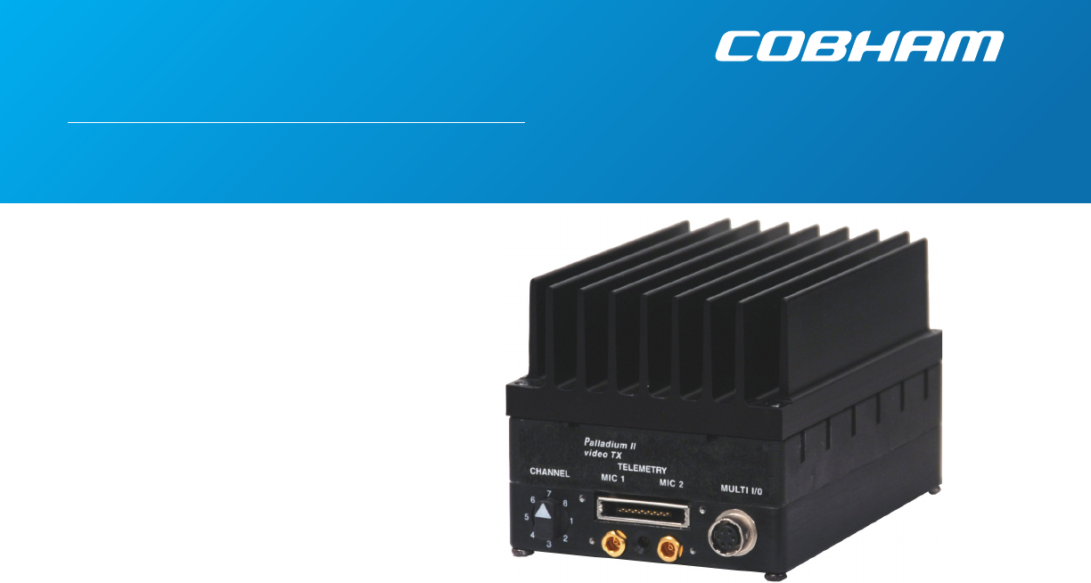
Palladium II Digital
COFDM Transmitter
Model Pd2-TX-1000 1W Output
The most important thing we build is trust

2PN OP1920331-S REV 0.002
copyright notice
Copyright © 2011
COBHAM All rights reserved. No part of this
document may be reproduced, transmitted,
transcribed, stored in a retrieval system or
translated into any language or computer
language, in any form or by any means,
including but not limited to electronic,
magnetic, mechanical, optical, chemical,
manual or otherwise, without the prior
written permission of COBHAM.
disclaimer
The information in the document is subject
to change without notice. COBHAM
makes no representations or warranties
with respect to the contents hereof, and
specifically disclaims any implied warranties
of merchantability or fitness for a particular
purpose. COBHAM reserves the right to
revise this publication and to make changes
from time to time in the content hereof
without obligation of COBHAM to notify
any person of such revision or changes.
how to contact COBHAM
For operator and troubleshooting
information, customers are encouraged
to refer to the details in this manual. For
additional clarification or instruction, or to
order parts, contact COBHAM.
Customer Service is available Monday
through Friday between the hours of 9:00
AM and 5:00 PM EST at:
Tel: 603-880-4411
Fax: 603-880-6965
Website: www.cobham.com/tcs
Email: dtc.info@cobham.com
DTC Communications, Inc.
dba Cobham Tactical Communications and
Surveillance
486 Amherst Street
Nashua, New Hampshire 03063

3
NOTE: Describes special issues you should be aware of
while using a particular function.
WARNING: Calls out situations in which
equipment could be damaged or a process could be
incorrectly implemented, but in which operator safety is
not a factor.
TIP: Describes application hints.
RF EXPOSURE STATEMENT
A separation distance of at least 20 cm must be
maintained between the antenna and the body of
the user or nearby persons. When the unit is used
consistent with the previous notice, it conforms to
the requirements of FCC Rules & Regulations, sections
1.1307 & 2.1091, as required by section 90.1217.
CAUTION! Use of antennas with gain above 2.1 dBi may
exceed Maximum Permissible Exposure (MPE) limits.
NOTE: This device is for occupational use only.
Occupational users are those persons who are exposed
as a consequence of their employment, provided these
persons are fully aware of and exercise control over
their exposure.
NOTE: DO not allow the device to directly contact the
skin due to warm operating temperatures.
manual conventions
Quick Start ....................................................................................................................4-5
Accessories ........................................................................................................................ 5
Introduction ........................................................................................................................ 6
Operation ........................................................................................................................ 7
Using your Palladium II Transmitter .............................................................................. 7
Changing your Transmitter Configuration ................................................................. 7
Heat Sink ....................................................................................................................8-9
Components .............................................................................................................. 10-11
Programming ......................................................................................................................11
Specifications .............................................................................................................. 12-13
Notes ......................................................................................................................14
Contact Us ......................................................................................................................15
TABLE OF CONTENTS
4
Antenna
Audio
Camera
Power Supply
Power Option
PALLADIUM II
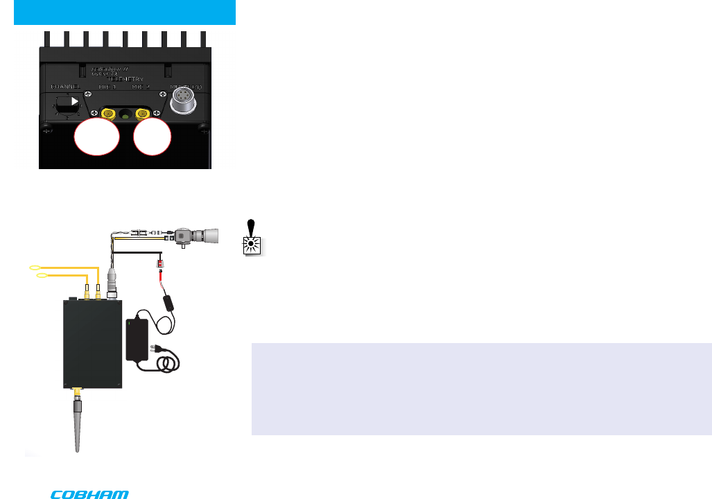
1. Connect the transmitter antenna to the SMA connector on the Palladium unit.
2. If you plan to use audio, connect one or two microphones to the Audio 1 and/or Audio 2
LEMO connectors. If using monaural, use Audio 1.
3. Connect power and video input via the Multi I/O cable to the 6-pin Hirose connector:
a. Attach your camera video input (75 ohm composite video source in PAL or NTSC) to
the Multi I/O cable BNC connector.
b. Apply the necessary power to your camera (use supplied cable or external source) and
turn ON.
c. Attach a 12 VDC power source to the Multi I/O cable via the Molex connector. The
input voltage range is from 10 to 16 VDC.
WARNING: Do not apply power to the transmitter unless an antenna or non-radiating
load is connected to the Antenna SMA connector.
Complete these steps:
Typical Wiring Configuration
QUICK START
A2
L
A1
R/M
Palladium Transmitter, Top View
2
3
Thermal Issues
Proper heat sink mounting is recommended for optimal performance. See page 8 for heat
sinking instructions.
5
QUICK START
4 Set to the required configuration as indicated by the channel numbers. Refer to the
Programming section on page 10 for more information on channel settings. Your
Transmitter is now operational. Confirm its signal with your Palladium Receiver.
Accessories
• 12 VDC 2.5A Power Supply & AC Line Cord
• Microphone, Body-Worn, (2)
• Power & Video Cable
• Camera Power Cable (2.1 mm plug)
• DC Power Cable, flying lead
• Camera Power Cable, flying lead
• Programming Cable
• Antenna, ANT2A
• 16-Pin Data Chaining & Control Connector Cable
• Transport Case
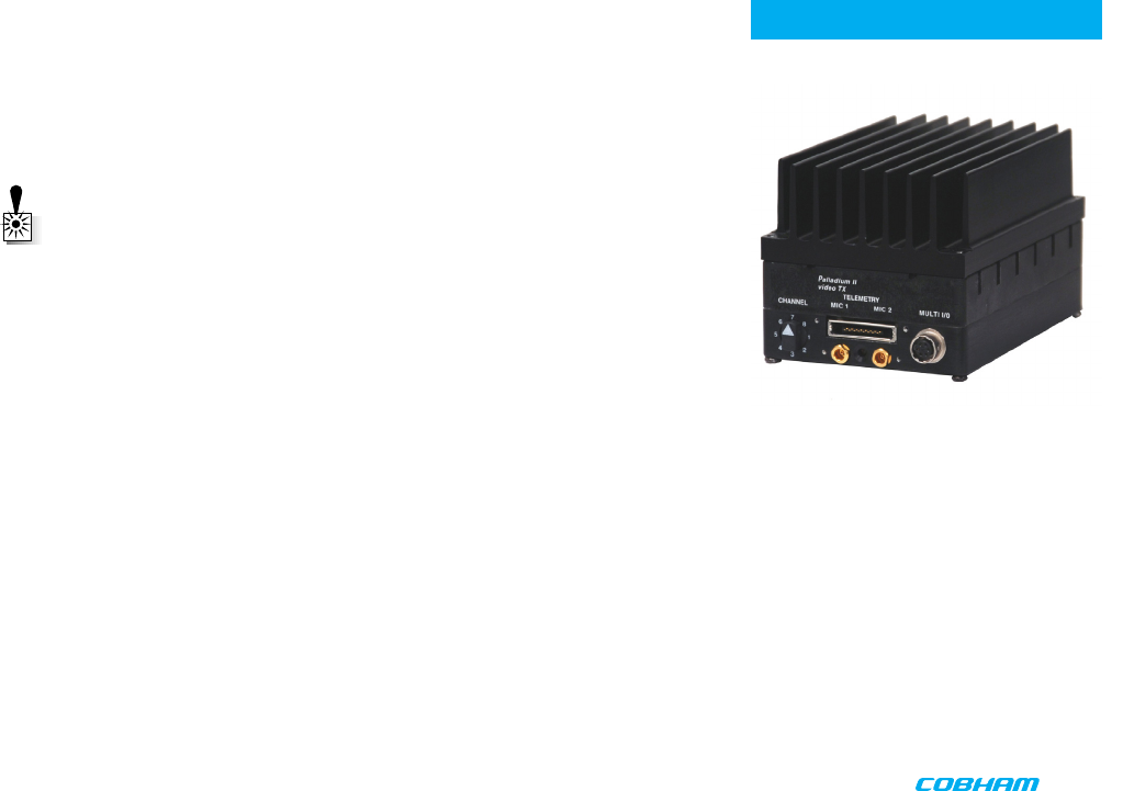
4
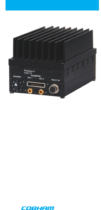
Palladium Pd2-TX-1000 Transmitter,
Front View
Antenna Connector
6
INTRODUCTION
Palladium Pd2-TX-1000
1 Watt Digital Transmitter
Palladium II
The Palladium II Series of digital video transmitters provide exceptional video quality in high
multipath environments. They are ideal for use inside buildings, in urban areas, and in other
applications where multipath would normally cause video tearing or breakup.
All Palladium II Series transmitters offer three bandwidth modes: DVB-T (6, 7, 8 MHz), Narrow
(2.5 MHz), and Ultra Narrow (1.25 MHz) channel spacing. DVB-T utilizes 2000 carriers to
transmit video and two channels of voice and data. Palladium II transmitters may be located
on adjacent channels without a guard band. AES 128-bit encryption ensures users of secure
communications.
The Palladium 1000 is a small transmitter with a 1 Watt RF power output. This unit is ideal
for concealments and shorter range robotic and UAV applications. The package is only 4.2”
x 2.8” x 2.5” (approximate dimensions not including connectors). Power consumption is 29
Watts maximum. All connections are conveniently located off the ends of the unit. The unit
is water-resistant if mounted with its SMA connector pointing directly upward (with antenna
connected).

7
OPERATION
Using your Palladium II Transmitter
Follow the instructions given in the Quick Start section on pages 4-5. When power is first
applied to the Palladium, the unit reverts to the indicated channel and RF ON state. The Alarm
LED may be ON, which indicates that there is no active video input.
Changing your Transmitter Configuration
The Palladium Transmitter can store up to 8 different configurations, which can be selected
with the Channel Control. Each of these configurations are programmed into the transmitter by
the factory at the time of order.
To cycle through your preconfigured channels rotate the knob to the next setting.
NOTE: FCC 90.203 (e) prohibits anyone other than the manufacturer, qualified service
or maintenance personnel from altering the frequency programming of the transmitter.
Please contact the factory for additional information regarding programming
frequencies.
8
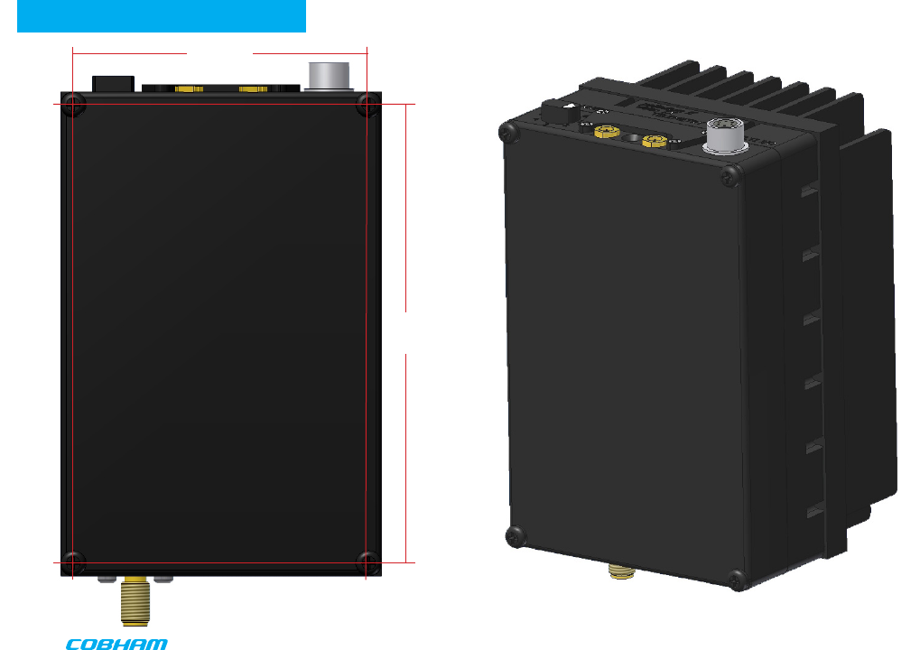
HEAT SINK
HEAT SINK
2.530
3.935
9
HEAT SINK
Palladium 1000 Heat Sink
The Palladium 1000 is supplied with a heat sink attached. DO NOT remove the heat sink unless
you have an alternate mounting surface that will dissipate the heat properly.
WARNING: The Palladium 1000 may become too hot to touch without a proper
heatsink attached, such as the one supplied. Damage to internal components may
occur if operated beyond the recommended temperature range. If placed in an
enclosure, proper ventilation and mounting is required. If designing a custom heatsink,
keep the transmitter chassis temperature at 50oC or less. The transmitter must be
mounted to a heatsink on the transmitter’s “blank side” as shown on page 8.
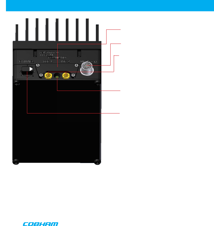
10
COMPONENTS
Audio 2 (left) and Audio 1 (right/mono) LEMO Conn. These connectors provide the audio
input connections to the transmitter. Either one or two audio inputs can be used with the
Palladium II Transmitter.
ALARM LED This red LED indicates a valid video signal is not present.
Controls/Connectors
Data Chaining & Control Connector This connector is normally covered.
Multi-I/O Connector The Multi-I/O Connector is covered on page 11.
Channel Switch This rotary switch selects from up to eight preprogrammed configura-
tions.
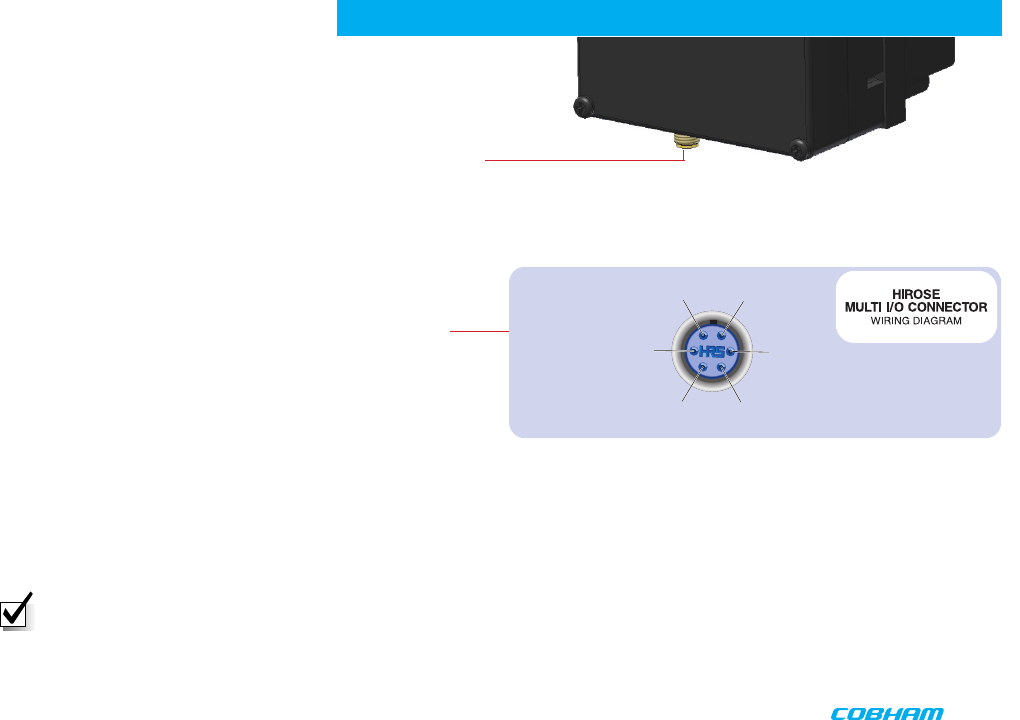
11
COMPONENTS and PROGRAMMING
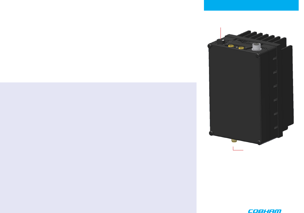
Transmitter Antenna Connector (SMA) This connector attaches to the
transmitter antenna and carries the RF output signal. Always ensure
the transmitter antenna is attached before operating the Palladium
Transmitter.
Muiti I/O Connector (6-pin Hirose) This connector provides
connections for the DC Power Input, DC Camera Power,
Programming, and 75 Ohm Composite Video Signal.
1 Ground
Video In 75 Ohm 6
RS232 In 5
RS232 Out 4
2 +V Power
10V - 16V
3 Camera Power Out 10V -16V
Programming
Frequency and channel configurations are programmed into the transmitter by the factory at
the time of order.
NOTE: FCC 90.203 (e) prohibits anyone other than the manufacturer, qualified service
or maintenance personnel from altering the frequency programming of the transmitter.
Please contact the factory for additional information regarding programming
frequencies.

12
Physical
Unit Dimensions not including heatsink or 4.25” x 2.75” x 1.25”
connectors (approx.) (10.8 cm x 7.0 cm x 3.2 cm)
Unit Dimensions including heatsink and 4.75” x 2.75” x 2.5”
connectors (approx.) (10.8 cm x 7.0 cm x 6.3 cm)
Weight
Weight without heatsink 9 oz (0.26 kg)
Weight including heatsink 1 lb 3 oz (0.54 kg)
Environmental
Operational Temp -10 degrees C to 50 degrees C
Power
Input Voltage 10 to 16 VDC
Power Consumption Fully Operational ~ 29 W max.,
Sleep Mode < 0.5 W
Control
PC Control Interface RS-232.
Memory Eight user-programmable configurations
Video Encoding
Compression Standard MPEG-2 w/ non-DVB modes, MPEG-4
DVB-T Compliant
Chrominance Profile 4:2:0
Line Standard PAL 625 or NTSC 525
Horizontal Resolution 704, 528, 480, 352 pixels (528 as standard)
Vertical Resolution 576 (625 lines) or 480 (525 lines)
SPECIFICATIONS

13
SPECIFICATIONS
Video Bitrates 1Mbps to 10 Mbps
Video Latency End to end delay of 54 milliseconds
Audio Encoding
Input Stereo or Dual Mono pair
Bitrates 28 kbps to 72 kbps depending on configuration
Sampling Frequency 32 kHz, 16 kHz or 8kHz
THD < 0.1% max
Response 20Hz to 15KHz, +/- 0.25dB depending on
configuration
Crosstalk > 55 dB min
S/N 60 dB RMS
Composite Video Input
Standards NTSC (with and without pedestal) or PAL
Specification Rec. ITU-R BT.470-4
Connector Hirose
Composite PAL and NTSC decoding Eight-bit comb filtering composite decoder
Analog Audio
Analog Audio Input +10 dBu
Nominal Level +4 dBu
Scrambling
Scrambling type Fixed key scrambling system
Algorithms offered include AES.
COFDM RF output
Output Frequency Band Dependent
Occupied Bandwidth 1.22/2.44 MHz
Power 1 Watt
Connector SMA
COFDM Standard Proprietary, 2.5 MHz channel bandwidth.
DVB-T 6, 7, 8 MHz Bandwidth

NOTES

15
CONTACT USCONTACT US
Contact Information
Customer Service is available Monday through Friday between the hours of 9:00 AM and 5:00 PM EST at:
(T) 603-880-4411
A complete listing of Contact Individuals can be located on our website at: www.cobham.com/tcs
Toll-Free 1 800 233 8639
North America Sales/Training
Office
2303 Dulles Station, suite 200
Herndon VA 20171
T: (703) 234 9311
Canadian Offices
120 Eileen Stubbs Avenue, Suite 200
Dartmouth, NS B3B 1Y1
T: (902) 468 3007
Toll free: 1 800 665 4648
F: (902) 468 3009
West Coast Offices
1916 Palomar Oaks Way, #100
Carlsbad, CA 92008
United States
T: (760) 496 0055
Toll-free: 1 888 880 9339
F: (760) 496 0057
East Coast Offices
486 Amherst St.
Nashua, NH 03063
United States
T: (603) 880 4411
Toll-Free: 1 800 233 8639
F: (603) 880 6965
486 Amherst Street • Nashua, New Hampshire 03063 • 603-880- 4411 www.cobham.com/tcs
Cobham Tactical Communications and Surveillance