DTC Communications PD2TX1000SV COFDM Video Transmitter User Manual
DTC Communications Inc. COFDM Video Transmitter
User Manual
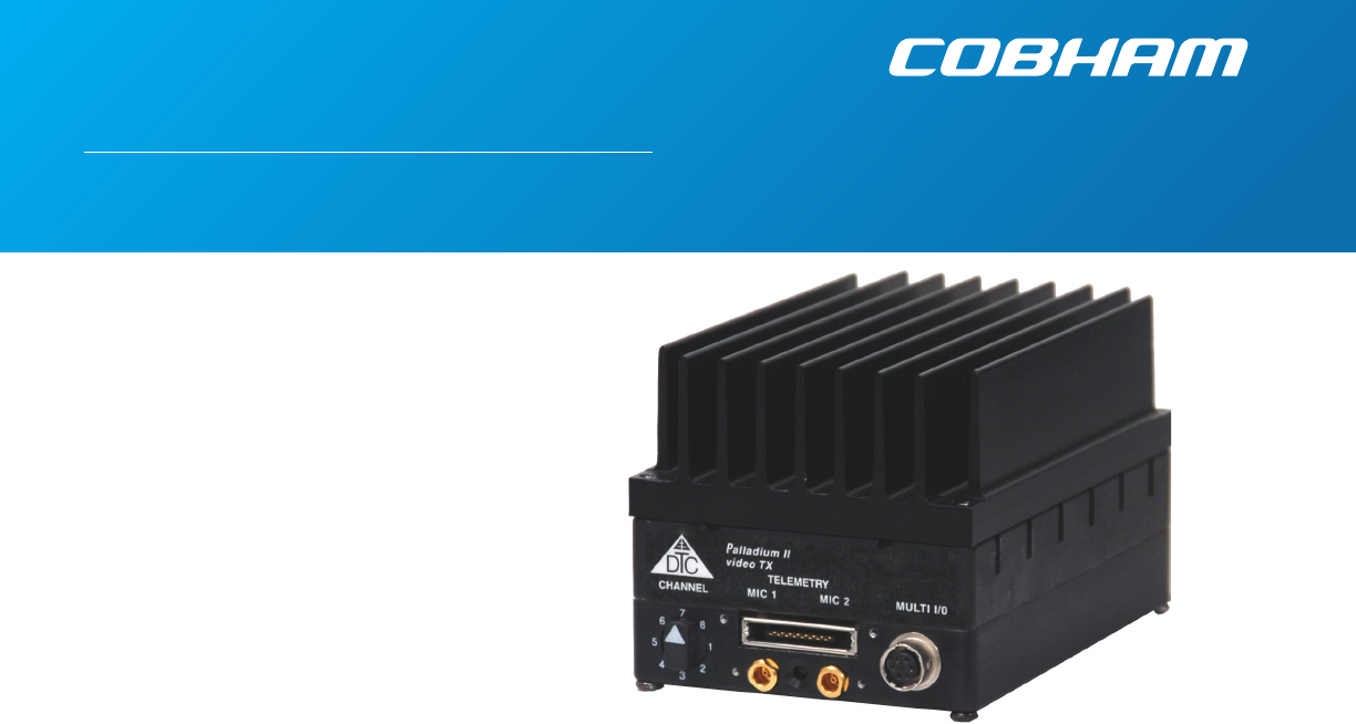
Palladium II Digital
COFDM Transmitter
Model Pd2-TX-1000 1W Output
The most important thing we build is trust

2PN OP1920331 REV. C
copyright notice
Copyright © 2005-2010
COBHAM All rights reserved. No part of this
document may be reproduced, transmitted, tran-
scribed, stored in a retrieval system or translated
into any language or computer language, in any
form or by any means, including but not limited
to electronic, magnetic, mechanical, optical,
chemical, manual or otherwise, without the prior
written permission of COBHAM.
disclaimer
The information in the document is subject
to change without notice. COBHAM makes
no representations or warranties with respect
to the contents hereof, and specifically dis-
claims any implied warranties of merchant-
ability or fitness for a particular purpose.
COBHAM reserves the right to revise this
publication and to make changes from time
to time in the content hereof without obliga-
tion of COBHAM to notify any person of
such revision or changes.
how to contact COBHAM
For operator and troubleshooting informa-
tion, customers are encouraged to refer to
the details in this manual. For additional
clarification or instruction, or to order parts,
contact COBHAM.
Customer Service is available Monday
through Friday between the hours of 9:00
AM and
5:00 PM EST at:
Tel: 603-880-4411
Fax: 603-880-6965
Website: www.cobham.com/dtc
Email: dtc.info@cobham.com
DTC Communications
dba Cobham Surveillance
486 Amherst Street
Nashua, New Hampshire 03063

3
NOTE: Describes special issues you should be aware of
while using a particular function.
WARNING: Calls out situations in which
equipment could be damaged or a process could be
incorrectly implemented, but in which operator safety is
not a factor.
TIP: Describes application hints.
RF EXPOSURE STATEMENT
A separation distance of at least 20 cm must be
maintained between the antenna and the body of
the user or nearby persons. When the unit is used
consistent with the previous notice, it conforms to
the requirements of FCC Rules & Regulations, sections
1.1307, 2.1091 & 2.1093, as required by section
90.1217.
NOTE: This device is for occupational use only.
Occupational users are those persons who are exposed
as a consequence of their employment, provided these
persons are fully aware of and exercise control over
their exposure.
NOTE: DO not allow the device to directly contact the
skin due to warm operating temperatures.
manual conventions
Quick Start ....................................................................................................................4-5
Accessories ........................................................................................................................ 5
Introduction ........................................................................................................................ 6
Operation ........................................................................................................................ 7
Using your Palladium II Transmitter .............................................................................. 7
Changing your Transmitter Configuration ................................................................. 7
Heat Sink ....................................................................................................................8-9
Components .............................................................................................................. 10-11
Programming .............................................................................................................. 12-19
System PC Controller Application Software ...........................................................12
Transmitter Control Application ...................................................................................13
Specifications .............................................................................................................. 20-21
Warranty ......................................................................................................................22
Contact Us ......................................................................................................................23
TABLE OF CONTENTS
4
Antenna
Audio
Camera
Power Supply
Power Option
PALLADIUM II
1. Connect the transmitter antenna to the SMA connector on the Palladium unit.
2. If you plan to use audio, connect one or two microphones to the Audio 1 and/or Audio 2
LEMO connectors. If using monaural, use Audio 1.
3. Connect power and video input via the Multi I/O cable to the 6-pin Hirose connector:
a. Attach your camera video input (75 ohm composite video source in PAL or NTSC) to
the Multi I/O cable BNC connector.
b. Apply the necessary power to your camera (use supplied cable or external source) and
turn ON.
c. Attach a 12 VDC power source to the Multi I/O cable via the Molex connector. The
input voltage range is from 10 to 16 VDC.
WARNING: Do not apply power to the transmitter unless an antenna or non-radiating
load is connected to the Antenna SMA connector.
Complete these steps:
Typical Wiring Configuration
QUICK START
A2
L
A1
R/M
Palladium Transmitter, Top View
2
3
Thermal Issues
Proper heat sink mounting is recommended for optimal performance. See page 8 for heat
sinking instructions.
5
QUICK START
4 Set to the required configuration as indicated by the channel numbers. Refer to the
Programming section on page 10 for more information on channel settings. Your
Transmitter is now operational. Confirm its signal with your Palladium Receiver.
Accessories
• 12 VDC 2.5A Power Supply & AC Line Cord
• Microphone, Body-Worn, (2)
• Power & Video Cable
• Camera Power Cable (2.1 mm plug)
• DC Power Cable, flying lead
• Camera Power Cable, flying lead
• Programming Cable
• Antenna, ANT2A
• Palladium II Configuration Software
• 16-Pin Data Chaining & Control Connector Cable
• Transport Case
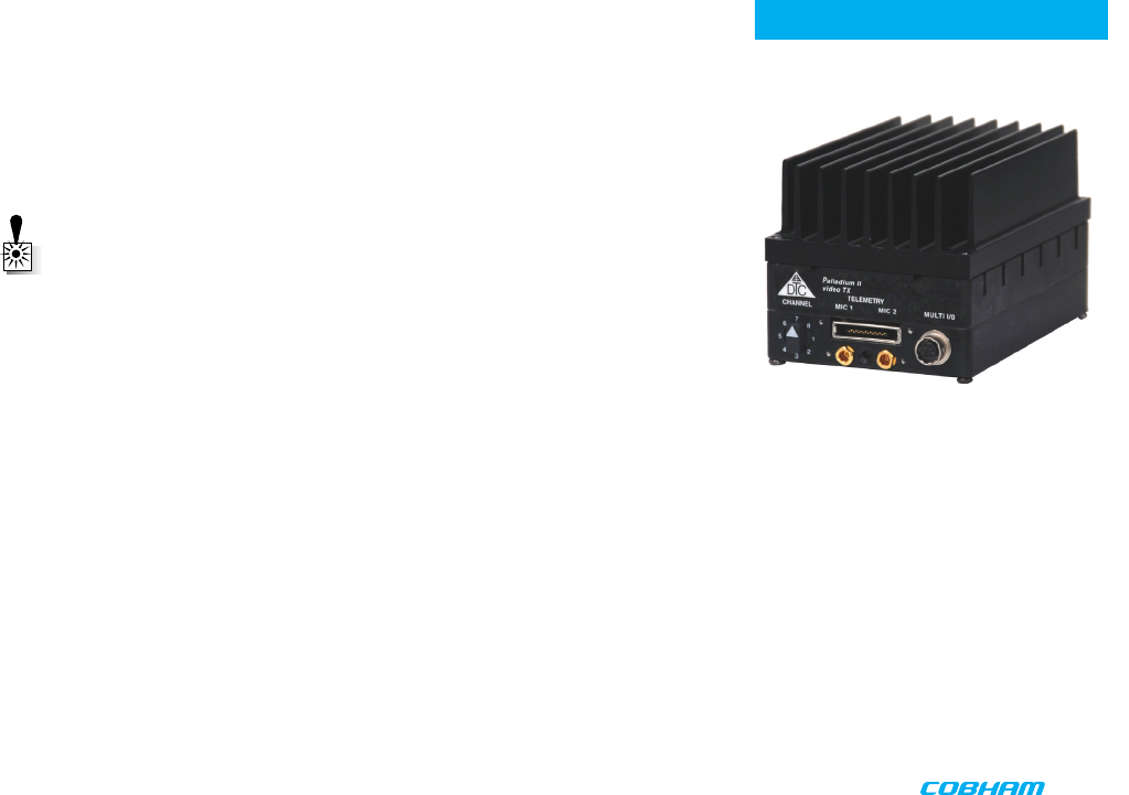
4
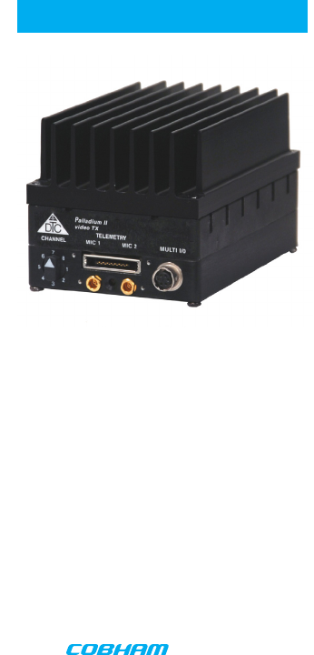
Palladium Pd2-TX-1000 Transmitter,
Front View
Antenna Connector
6
INTRODUCTION
Palladium Pd2-TX-1000
1 Watt Digital Transmitter
Palladium II
The Palladium II Series of digital video transmitters provide exceptional video quality in high
multipath environments. They are ideal for use inside buildings, in urban areas, and in other
applications where multipath would normally cause video tearing or breakup.
All Palladium II Series transmitters offer three bandwidth modes: DVB-T (6, 7, 8 MHz), Narrow
(2.5 MHz), and Ultra Narrow (1.25 MHz) channel spacing. DVB-T utilizes 2000 carriers to
transmit video and two channels of voice and data. Palladium II transmitters may be located
on adjacent channels without a guard band. AES 128-bit encryption ensures users of secure
communications.
The Palladium 1000 is a small transmitter with a 1 Watt RF power output. This unit is ideal
for concealments and shorter range robotic and UAV applications. The package is only 4.2”
x 2.8” x 2.5” (approximate dimensions not including connectors). Power consumption is 29
Watts maximum. All connections are conveniently located off the ends of the unit. The unit
is water-resistant if mounted with its SMA connector pointing directly upward (with antenna
connected).

7
OPERATION
Using your Palladium II Transmitter
Follow the instructions given in the Quick Start section on pages 4-5. When power is first
applied to the Palladium, the unit reverts to the indicated channel and RF ON state. The Alarm
LED may be ON, which indicates that there is no active video input.
Changing your Transmitter Configuration
The Palladium Transmitter can store up to 8 different configurations, which can be selected
with the Channel Control. Each of these configurations can be programmed into the
transmitter with the supplied DTC Programming Software and a Windows PC. Refer to the
Programming section on page 10 for more information.
To cycle through your preconfigured channels rotate the knob to the next setting.
8
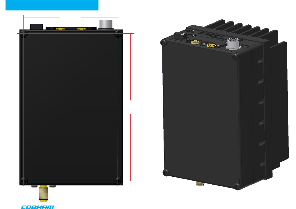
HEAT SINK
HEAT SINK
2.530
3.935
9
HEAT SINK
Palladium 1000 Heat Sink
The Palladium 1000 is supplied with a heat sink attached. DO NOT remove the heat sink unless
you have an alternate mounting surface that will dissipate the heat properly.
WARNING: The Palladium 1000 may become too hot to touch without a proper
heatsink attached, such as the one supplied. Damage to internal components may
occur if operated beyond the recommended temperature range. If placed in an
enclosure, proper ventilation and mounting is required. If designing a custom heatsink,
keep the transmitter chassis temperature at 50oC or less. The transmitter must be
mounted to a heatsink on the transmitter’s “blank side” as shown on page 8.
10
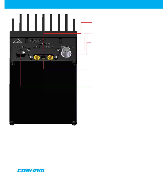
COMPONENTS
Audio 2 (left) and Audio 1 (right/mono) LEMO Conn. These connectors provide the audio
input connections to the transmitter. Either one or two audio inputs can be used with the
Palladium II Transmitter.
ALARM LED This red LED indicates a valid video signal is not present.
Controls/Connectors
Data Chaining & Control Connector This connector is normally covered.
Multi-I/O Connector The Multi-I/O Connector is covered on page 11.
Channel Switch This rotary switch selects from up to eight preprogrammed configura-
tions.
11
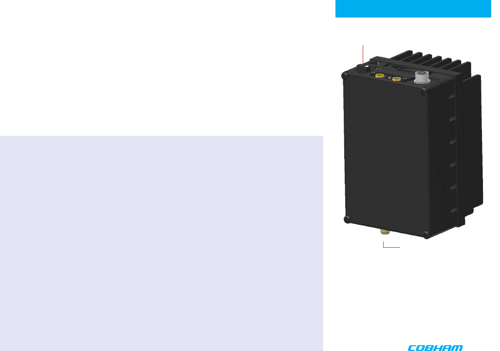
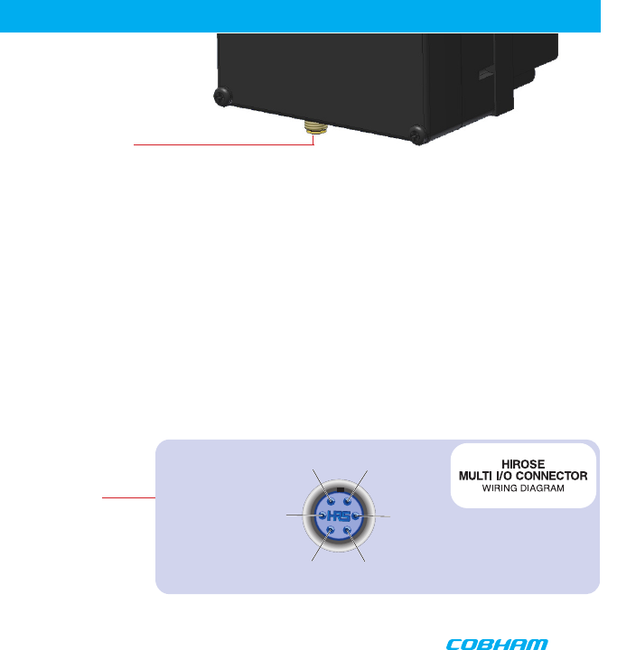
COMPONENTS
Transmitter Antenna Connector (SMA) This connector attaches to the
transmitter antenna and carries the RF output signal. Always ensure
the transmitter antenna is attached before operating the Palladium
Transmitter.
Muiti I/O Connector (6-pin Hirose) This connector provides
connections for the DC Power Input, DC Camera Power,
Programming, and 75 Ohm Composite Video Signal.
1 Ground
Video In 75 Ohm 6
RS232 In 5
RS232 Out 4
2 +V Power
10V - 16V
3 Camera Power Out 10V -16V
12
Antenna
Audio
Camera
Power Supply
Power Option
PALLADIUM II
PROGRAMMING
System PC Controller Application Software
Advanced control of the system is available by using the PC control
application software. Typically users may want to customize the default configurations to con-
trol settings such as frequency, scrambling keys, modulation parameters, and video resolution.
The transmitter is controlled by the application DTC_tx_ctrl_v1_3.exe
(or higher) available on the CD delivered with the product.
A PC is required with an available RS232 Serial COM port to control the transmitter.
Installation of the control program is as simple as copying the file from the CD to a suitable
location on the PC. No install shield routine is launched. Note that the application generates its
own log and initialization files, so it is best to create a dedicated directory for these applica-
tions, perhaps with links to the applications from the desktop of the PC.
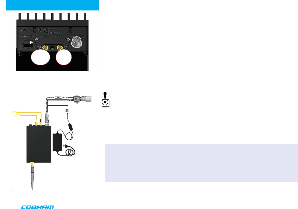
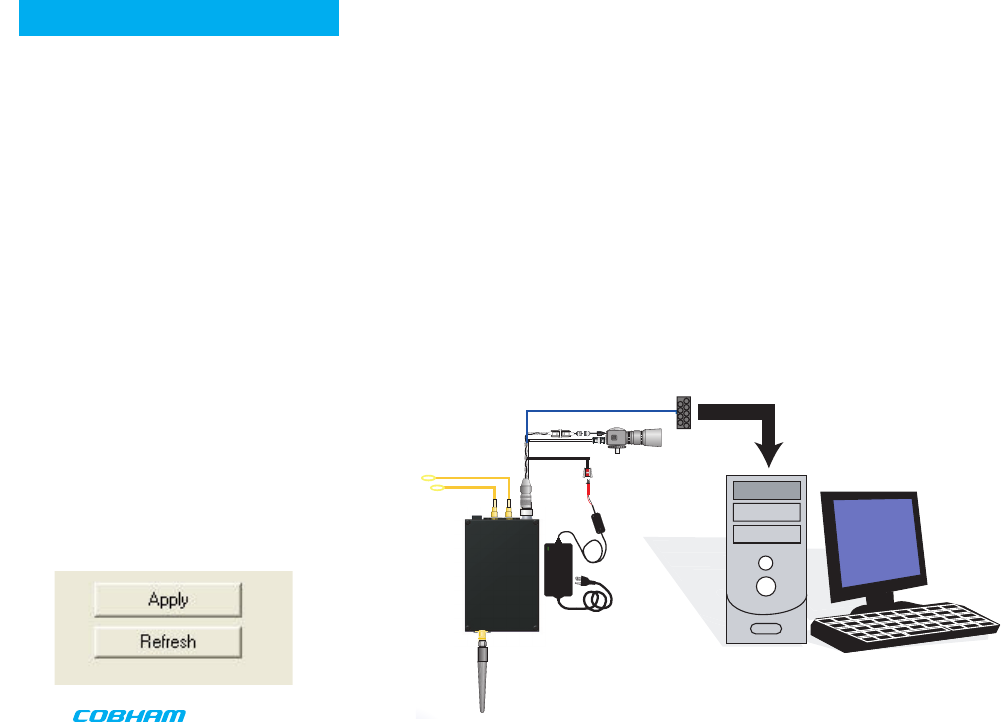
Getting Started
•Use the supplied programming cable to con-
nect the chosen COM port of your PC to the
transmitter to be configured.
•Launch the application by double clicking or
using the Run...
command.
•Connection with a transmitter should be au-
tomatic, but the user can force selection of
the correct COM port using the drop down,
followed by the Connect button.
•Select the channel to be configured from
the unit’s front panel
Channel Switch.
•Click Refresh in the application to display the
current configuration.
•Update the current settings in the applica-
tion, then click Apply to save to memory.
PROGRAMMING CABLE to
PC SERIAL RS-232 PORT
AUDIO INPUT(S)
ANTENNA
10 AA
BATTERY
PACK
TELEMETRY
Palladium II
VIDEO TX
PROGRAMMING
CABLE
To PC Serial
RS-232 PORT
13
PROGRAMMING
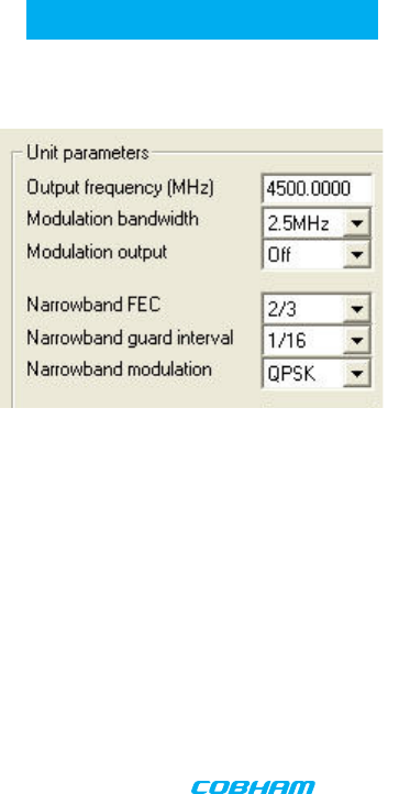
Transmitter Control Application
Output Frequency (MHz)
The Output Frequency setting allows selection of TX output frequency in increments of 0.250 MHz within
the allowed tuning range of the unit. If the unit is set to a frequency that is not an integer multiple of 0.25
MHz, the unit will be automatically set to the closest frequency that is an integer multiple of 0.25MHz.
Modulation Bandwidth
Modulation Bandwidth is the actual channel bandwidth that the wireless video link will occupy. The DVB-T
compliant mode requires a bandwidth setting of 6, 7 or 8 MHz. The narrowband mode bandwidth is either
1.25 or 2.5 MHz. Narrower bandwidths increase receiver sensitivity and extend the maximum distance of
the link, however video quality and latency will suffer. Normal default for good quality video is 2.5MHz. The
modulation bandwidth may be set to 1.25 MHz, 2.5 MHz, 6 MHz, 7 MHz, or 8 MHz.
Modulation Output
This control is used to turn ON and OFF the RF output. It must be ON for operation. Turn the transmitter RF
power ON by selecting ON and Apply from the application.
Narrowband FEC
Narrowband FEC sets the forward error correction rate in the narrow bandwidth modes of 1.25 or 2.5 MHz.
Tthe two rates are available are 1/3 and 2/3; the normal default setting for good quality video is 2/3. Chang-
ing the FEC rate to 1/3 will extend the receiver sensitivity by 2 to 3 dB at the
expense of degraded video quality and longer latency.
Narrowband Guard Interval
Narrowband guard interval is used in the narrowband modes of 1.25 and 2.5MHz to adjust for varying
multi-path delay conditions. The default is
1/16 however 1/8 can be selected if necessary to deal with extreme multi-path delays on long links. Select-
ing 1/8 guard interval could cause a degradation in video quality and latency.
Narrowband Modulation
Narrowband modulation is used in the narrowband modes to select between QPSK and 16QAM
modulation. For best range with good video quality, QPSK is used; 16QAM will give better video quality but
will cut down the link range by approximately 50%.
14
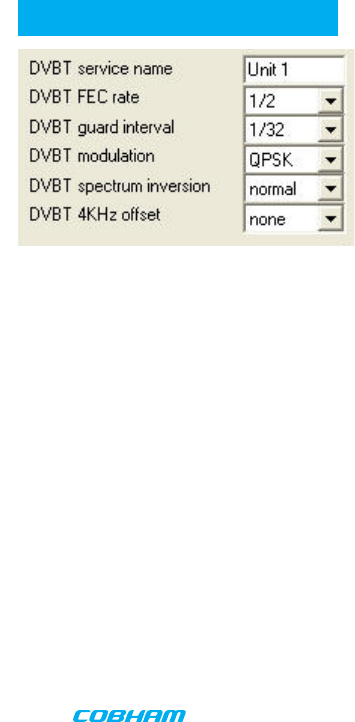
PROGRAMMING
DVBT Service Name
DVB-T service name is a place to assign a name for the DVB-T configuration. Press Apply to
save the new name.
DVBT FEC Rate
DVB-T FEC rate selects forward error correction rates in the wideband DVB-T modes. Options
are 1/2, 2/3, and 3/4, with 1/2 giving best range and 3/4 possibly giving better video quality
under certain conditions, recommended default is 1/2.
DVBT Guard Interval
DVB-T guard interval selects guard intervals in the wideband DVB-T modes between 1/32 and
1/4. Use the smallest guard interval that will allow reliable low error rate communications, this
parameter may need to be adjusted when the link is relocated; the recommended default is
1/16.
DVBT Modulation
DVB-T modulation selects the modulation used in the wideband DVB-T mode. Modulations
QPSK, 16QAM, or 64QAM can be selected. QPSK will give best distance and in most cases very
good video quality and low latency.
DVBT Spectrum Inversion
DVB-T spectrum inversion allows flipping the modulated spectrum to compensate for spectrum
inversion that may take place on the receiver side due to high side LO injection.
DVBT 4 KHz Offset
DVB-T 4 KHz offset is not normally used but might improve BER in cases where the TX upcon-
verter I/Q balance is poor.
15
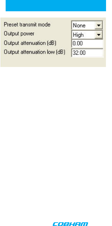
PROGRAMMING
Preset Transmit Mode
Preset transmit mode allows the user a convenient means of automatically setting bandwidth,
FEC, modulation and video frame rate/compression based on link distance requirements. Op-
tions are: None (preset mode not used), Short Range, Medium Range, Long Range, Ultra Long
Range.
Output Power
Output power selects one of two output power attenuator settings; low power or high power,
typically the low power setting is the larger of the two attenuator settings and is used, for
instance, if a power amplifier is added to the transmitter and the output power needs to be
lowered substantially to prevent overloading the input of the power amplifier.
Output Attenuation (dB)
Output attenuation (dB) is the high power attenuator setting.
This control can be used to make minor adjustments to the output power level, but in normal
operation should NOT be changed from factory
settings. (0 attenuation = full output power, greater than 0 attenuation = reduced power in 0.25
dB steps.)
Output Attenuation low (dB)
Output attenuation low (dB) is the low power attenuator setting.
16
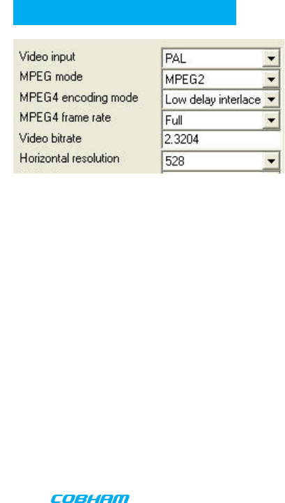
PROGRAMMING Video Input
Video input selects the video format going into the MPEG video compressor. Options are: OFF
(no video input typically used when link is used for data only), PAL, NTSC, NTSC no pedestal,
S-Video PAL, S-Video NTSC, S-Video NTSC no pedestal.
MPEG Mode
MPEG mode selects the MPEG compression being used, options are: MPEG2 or MPEG4. MPEG4
mode has to be used when in the 1.25 MHz bandwidth mode since this mode uses a nonstandard
frame rate that is not supported by MPEG2.
MPEG4 Encoding Mode
MPEG4 encoding mode selects the characteristics of the MPEG4 compression. Options are: low
delay interlaced, standard delay interlaced, low delay progressive, standard delay progressive, and
SIF. Interlaced scanning is what is used in conventional over-the-air video. Progressive scan is
available on some cameras and involves scanning an entire frame in one pass rather than two in interlaced
scanning. SIF is a bandwidth-conserving camera scan mode that cuts resolution in half in both the horizon-
tal and vertical.
MPEG4 Frame Rate
MPEG4 frame rate selects the frame rate used in the MPEG4 mode, full frame rate is 30 fps for NTSC and
25 fps for PAL a frame rate of 1/2 or less has to be used in 1.25 MHz bandwidth mode. Options are: Full,
1/2, 1/4, 1/8. or 1/24.
Video Bitrate (status only)
Video bitrate is a status window that will display the video transport data rate, this varies with bandwidth,
modulation, FEC rate and guard interval. The rate will increase with bandwidth and higher levels of modula-
tion, it will go down as the FEC rate and guard interval are increased. The video bit rate will also decrease
as other service options are activated such as audio and data channels. As a rule video quality and latency
improve as the bit rate is increased.
Horizontal Resolution
Horizontal resolution determines the maximum number of horizontal Pixels that can be sampled by the
video encoder. For optimal performance this setting should be set to the first value that exceeds the hori-
zontal resolution of the camera in use. Options are: 352, 480, 528, 704 pixels.
17
PROGRAMMING
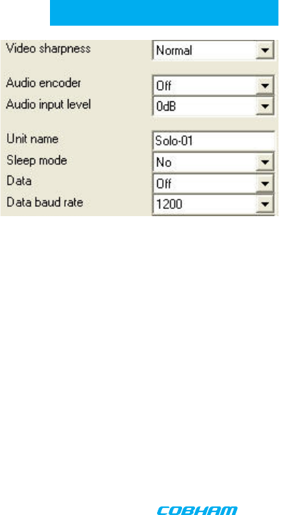
Video Sharpness
Video sharpness is a filter that may be switched in to smooth out blockiness in the
video.
Audio Encoder
Audio encoder selects quantity of active audio channels (2 maximum), sampling rate
(8, 16 or 32 KHz) which determines upper frequency response, and sampling bits (8 or
12) which determines audio signal to noise. Options are: Off, 8 KHz 8 bit stereo, 16 KHz
8 bit mono, 16 KHz 8 bit stereo, 32 KHz 8 bit mono, 32 KHz 8 bit stereo, 32 KHz 12 bit
mono, 32 KHz 12 bit stereo.
Audio Input Level
Audio input level selects the audio preamp gain level, options are:
0 dB, 12 dB, 24 dB, 36 dB, 48 dB. Use 24 dB for DTC supplied microphones. Note: 3.5
VDC phantom power is at the microphone input for powering electret condenser
microphones.
Unit Name
Unit name allows the user to enter a name (up to 8 characters) for the transmitter that will be
stored in memory.
Sleep Mode
Sleep mode shuts down most functions in the transmitter except the control functions. This
can be used to conserve battery power and yet allow the transmitter to become active again
with a simple command.
Data
Data allows activation of the RS232 half duplex serial data channel and to select parity mode.
Data Baud Rate
Data baud rate selects data channel baud rate, standard rates between 1200 and 115,200 baud
are available.
18
PROGRAMMING
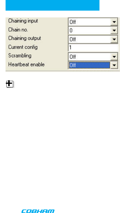
Chaining Input
Chaining input activates the chaining data port. This is not normally used except in
repeaters and high speed data transmission products.
Chain Number
Chain no. (not normally used) assigns a chaining tag number to the stream associated
with the transmitter’s video encoder. This can be user-defined to 0, 1, 2, 3, 4, 5, 6, 7, 8,
or 9. Normally 0.
Chaining Output
Chaining output (not normally used) assigns the output of the video encoder to the
chaining port. Normally OFF.
Current Configuration
Current config indicates the preset that is currently being programmed or viewed, this should
be the same as the preset selected by the channel switch. Enter channel number and click Ap-
ply to change.
Scrambling
Scrambling selects 3 different scrambling options: OFF (no scrambling), AES128, AES256 (op-
tional), or ABS (a proprietary 32 bit scrambling algorithym).
Heartbeat Enable
Heartbeat enable activates a flashing block on the screen video graphic to indicate that a link is
still functioning even if there is no motion on screen.
NOTE: Chaining is digital signal input
and output through the 16-pin Data,
Chaining, and Control Connector.
19
PROGRAMMING
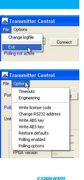
File
Change Logfile – opens a standard Windows file save dialog box which allows the user to
change the path and name of the log file generated by the application.
Exit – exits the control application.
Options
Timeouts – password protected access to change timeouts used during the serial communi-
cations between the unit and the controller.
Engineering – password protected access to further diagnostic and calibration features.
Write License Code – open a further password protected box for entering license codes for
future upgrade.
Change RS232 address – Changes RS232 address of configuration port, which is normally
set to 1.
Write AES Key – opens a dialog box for entering a customer-selected
scrambling key. A key is a combination of 32 hexadecimal characters (64 for optional 256-
bit encryption). Hexadecimal characters are 0, 1, 2, 3, 4, 5, 6, 7, 8, 9, A, B, C, D, E, and F. The
receiver and transmitter must have identical AES keys.
Restore Defaults – restores factory default settings in the transmitter. User should NOT
select Restore Defaults.
Polling Enabled – selecting this option makes the control application automatically refresh
the data presented to the user every few seconds.
Polling Options – selecting this option opens a dialog box for entering a customer-selected
polling interval (in milliseconds).

20
Physical
Unit Dimensions not including heatsink or 4.25” x 2.75” x 1.25”
connectors (approx.) (10.8 cm x 7.0 cm x 3.2 cm)
Unit Dimensions including heatsink and 4.75” x 2.75” x 2.5”
connectors (approx.) (10.8 cm x 7.0 cm x 6.3 cm)
Weight
Weight without heatsink 9 oz (0.26 kg)
Weight including heatsink 1 lb 3 oz (0.54 kg)
Environmental
Operational Temp -10 degrees C to 50 degrees C
Power
Input Voltage 10 to 16 VDC
Power Consumption Fully Operational ~ 29 W max.,
Sleep Mode < 0.5 W
Control
PC Control Interface RS-232.
Memory Eight user-programmable configurations
Video Encoding
Compression Standard MPEG-2 w/ non-DVB modes, MPEG-4
DVB-T Compliant
Chrominance Profile 4:2:0
Line Standard PAL 625 or NTSC 525
Horizontal Resolution 704, 528, 480, 352 pixels (528 as standard)
Vertical Resolution 576 (625 lines) or 480 (525 lines)
SPECIFICATIONS

21
SPECIFICATIONS
Video Bitrates 1Mbps to 10 Mbps
Video Latency End to end delay of 54 milliseconds
Audio Encoding
Input Stereo or Dual Mono pair
Bitrates 28 kbps to 72 kbps depending on configuration
Sampling Frequency 32 kHz, 16 kHz or 8kHz
THD < 0.1% max
Response 20Hz to 15KHz, +/- 0.25dB depending on
configuration
Crosstalk > 55 dB min
S/N 60 dB RMS
Composite Video Input
Standards NTSC (with and without pedestal) or PAL
Specification Rec. ITU-R BT.470-4
Connector Hirose
Composite PAL and NTSC decoding Eight-bit comb filtering composite decoder
Analog Audio
Analog Audio Input +10 dBu
Nominal Level +4 dBu
Scrambling
Scrambling type Fixed key scrambling system
Algorithms offered include AES.
COFDM RF output
Output Frequency Band Dependent
Occupied Bandwidth 1.22/2.44 MHz
Power 1 Watt
Connector SMA
COFDM Standard Proprietary, 2.5 MHz channel bandwidth.
DVB-T 6, 7, 8 MHz Bandwidth

TWO YEAR WARRANTY
DTC Communications, Inc. (DTC) warrants its RF transmitting and receiving products to be free from defects in workmanship or mate-
rial for a period of two (2) years from the date of shipment unless otherwise stated.
The liability of DTC, Inc. under this warranty is limited to replacing, repairing, or issuing credit, at option, for any products, which are
returned by the purchaser during such warranty period, provided:
DTC is notified and a Repair Authorization Number is issued by DTC Customer Service within 30 days after discovery of such defects
by Customer.
The defective units are returned to DTC with transportation charged Prepaid by the Customer.
Product damaged in shipment must be reported to and claim forms filed with the Carrier by the
Customer. In shipments to the factory, notice and claim procedures will be initiated by DTC.
DTC’s examination of such products shall disclose to its satisfaction that such defects exist and have not been caused by mis-
use, misapplication, neglect, improper installation, improper storage, alteration, physical damage or accidents.
The warranty shall not apply to material or accessories ordinarily susceptible to field damage or of a disposable nature. Exam-
ples include batteries, antennas, microphones, headsets, cases, accessory bags, etc. The warranty shall not apply to Engineering
Prototypes or Customer requested modifications to electronic circuits.
This warranty does not apply to and DTC does not independently warrant items or systems sold by DTC which are produced
by other manufacturers. With respect to such items, the Customer shall look to the warranty of the original manufacturer and
DTC disclaims all warranty, expressed or implied.
Nothing in this warranty, or any statement, brochure, bulletin, or advertisement is to be interpreted as establishing the suit-
ability of any product for particular application or use. Applications of the product and the determination of suitability for any
application, is the sole responsibility of the Customer.

23
CONTACT USCONTACT US
Contact Information
Nashua Main Office Numbers
486 Amherst Street
Nashua, New Hampshire 03063 USA
(T) 603 880- 4411
(F) 603 880- 6965
Toll Free in the USA
1- 800 233- 8639
REGIONAL SALES MANAGERS
Howard Rich
toll free (888) 819- 8570
voice (860) 626- 8570
fax (860) 626- 8571
NY, MA, CT, RI, PA, NJ, MD, DE, WV, DC
hrich@cobham.com
Gary Nichols
toll free (866) 794-2823
voice (765) 473-8917
fax (765) 473-8920
MN, WI, MI, IA, MO, IL, IN, OH, KY, NE
gnichols@cobham.com
Joe Parkinson
toll free (800) 515-0599
voice (928) 443-9399
fax (928) 443-9302
CA, AZ, NV, HI, UT, AK
jparkinson@cobham.com
Inside Sales
Law Enforcement
1-800 233-8639
Military
1-800 233-8639
OEM
1-800 233-8639
A complete listing of Contact Individuals can
be located on our website at:
www.cobham.com/dtc
Ed Bryant
toll free (800) 396-0295
voice (903) 725-7229
fax (903) 725-6952
CO, KS, OK, AR, NM, TX, LA
ebryant@cobham.com
Phil Desmond
toll free (800) 233-8639
voice (603) 546-2217
fax (603) 880-6965
NH, VT, ME, WA, OR, ID, MT, ND,
WY, SD
pdesmond@cobham.com
Frank Prioli
toll free (800) 246-2610
voice (727) 392-4761
fax (727) 320-0509
FL, GA, AL, MS, TN, NC, SC, VA
fprioli@cobham.com
Federal Sales
Len Corasaniti
voice (202) 870-3905
fax (410) 544-6538
CO, KS, OK, AR, NM, TX, LA
lcorasaniti@cobham.com
486 Amherst Street • Nashua, New Hampshire 03063 • 603-880- 4411 www.cobham.com/dtc
Cobham Surveillance