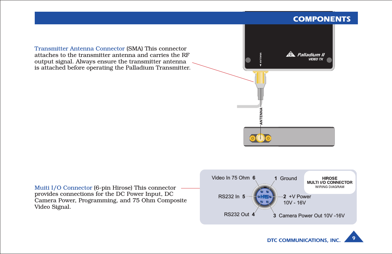
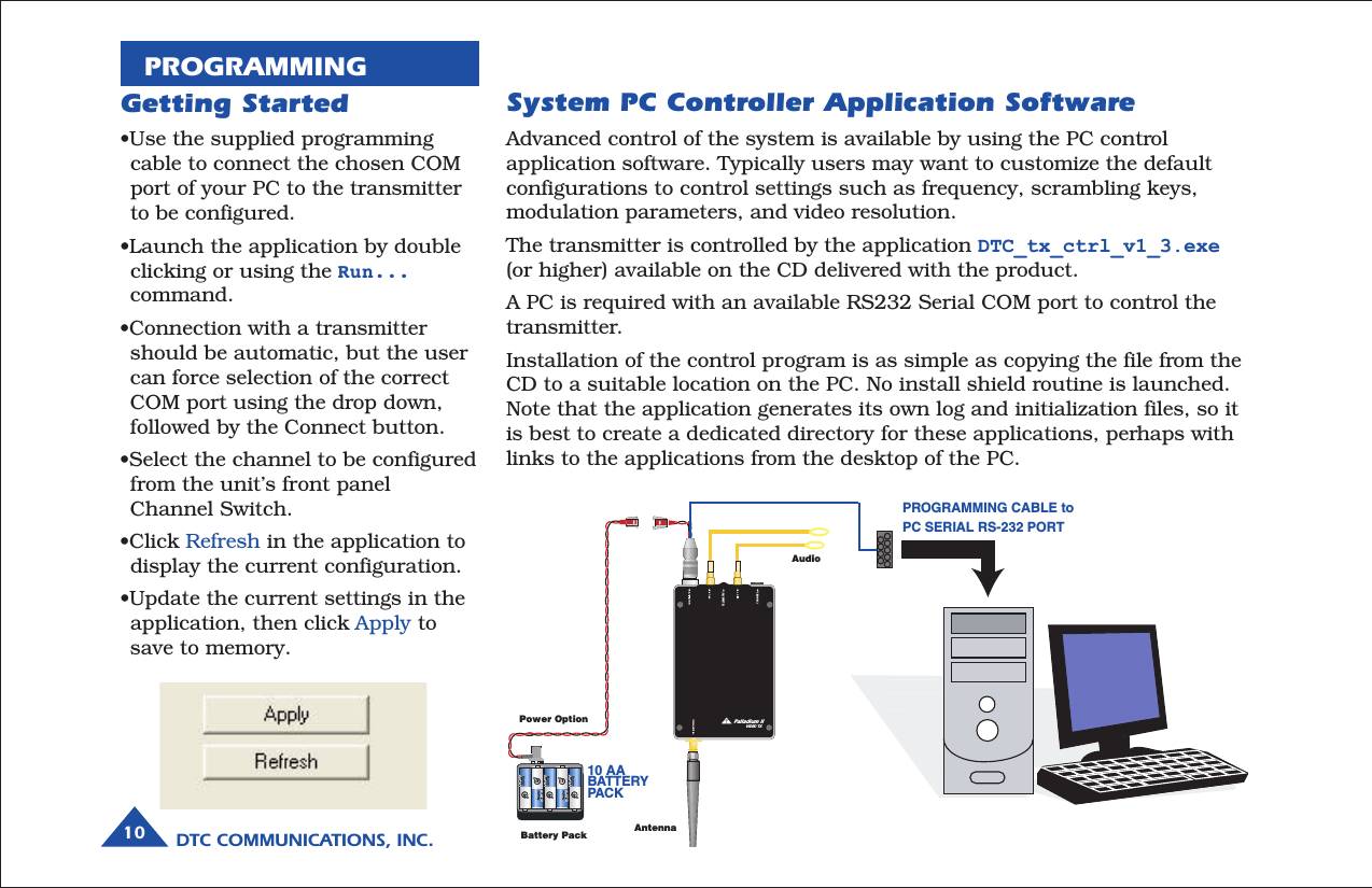
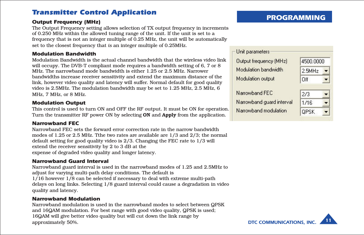
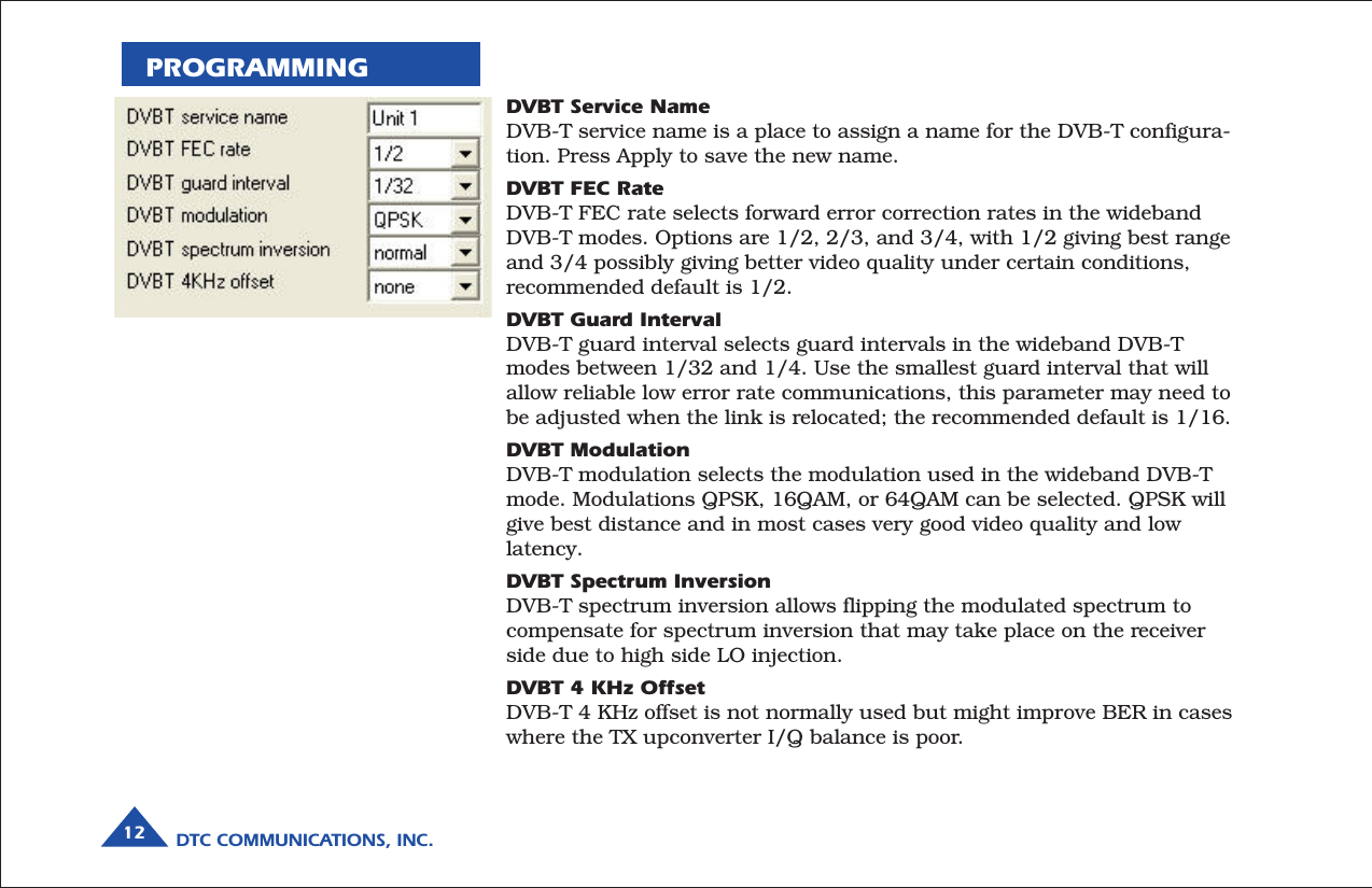
DTC Communications PD2TX100S COFDM Video Transmitter User Manual OP1920492Palladium2txRev003

DTC Communications Inc. COFDM Video Transmitter OP1920492Palladium2txRev003

Manual

COFDM TransmitterModel Pd2-TX-100 100 mW OutputPalladium II DigitalTELEMETRY CHANNEL Palladium IIVIDEO TXCOMMUNICATIONS
DTC COMMUNICATIONS, INC.2warrantyDTC warrants its manufactured componentsagainst defects in material and workmanshipfor a period of two (2) years, commencing onthe date of original purchase.Products manufactured by others that areapproved for use with DTC equipment arewarranted for the manufacturer’s warrantyperiod, commencing from the date of shipmentfrom DTC.PN OP1920492 REV 0.003copyright noticeCopyright © 2005 - 2008DTC Communications, Inc. All rightsreserved. No part of this document may bereproduced, transmitted, transcribed, storedin a retrieval system or translated into anylanguage or computer language, in any formor by any means, including but not limited toelectronic, magnetic, mechanical, optical,chemical, manual or otherwise, without theprior written permission of DTCCommunications, Inc.disclaimerThe information in the document is subject tochange without notice. DTC makes norepresentations or warranties with respect tothe contents hereof, and specifically disclaimsany implied warranties of merchantability orfitness for a particular purpose. DTC reservesthe right to revise this publication and tomake changes from time to time in thecontent hereof without obligation of DTC tonotify any person of such revision or changes.trademarksTrademarks of DTC Communications, Inc.include:• DTC• MiniPIXTM• SplitPIXTM• DynaViewTM• PalladiumTM• ArmorNetTMOther product names used in this manual arethe properties of their respective owners.how to contact DTCFor operator and troubleshooting information,customers are encouraged to refer to thedetails in this manual. For additionalclarification or instruction, or to order parts,contact DTC.Customer Service is available Monday throughFriday between the hours of 9:00 AM and5:00 PM EST at:Tel: 603-880-4411Fax: 603-880-6965Website: www.dtccom.comEmail: info@dtccom.com486 Amherst StreetNashua, New Hampshire 03063
DTC COMMUNICATIONS, INC. 3NOTE: Describes special issues you shouldbe aware of while using a particular function.WARNING: Calls out situations in whichequipment could be damaged or a processcould be incorrectly implemented, but inwhich operator safety is not a factor.TIP: Describes application hints.RF EXPOSURE STATEMENTNOTE: Unless specificaly designed for body-worn applications, the antenna must be keptat least 20 cm away from the body of theuser.NOTE: Do not allow the device to directlycontact the skin due to warm operatingtemperatures.manual conventionsQuick Start ............................................................................ 4-5Accessories ............................................................................... 5Introduction ............................................................................... 6Operation ............................................................................... 7Using your Palladium II Transmitter ............................................. 7Changing your Transmitter Configuration .................................... 7Components ........................................................................... 8-9Programming ...................................................................... 10-17System PC Controller Application Software .............................. 10Transmitter Control Application ................................................. 11Specifications ..................................................................... 18-19Notes ........................................................................ 20-21Warranty ............................................................................. 22Contact Us ............................................................................. 23TABLE OF CONTENTS
DTC COMMUNICATIONS, INC.4TELEMETRY CHANNEL Palladium IIVIDEO TXAntennaAudioCameraBattery PackPower Option1Connect the transmitter antenna to the SMA connector on the bottom ofthe Palladium unit.2If you plan to use audio, connect one or two microphones to the Audio 1and/or Audio 2 LEMO connectors. If using monaural, use Audio 1.3Connect power and video input via the Multi I/O cable to the 6-pinHirose connector:a Attach your camera video input (75 ohm composite video source in   PAL or NTSC) to the Multi I/O cable BNC connector.b Apply the necessary power to your camera (use supplied cable or   external source) and turn ON.c Attach a 12 VDC power source (such as the supplied battery pack or   the AC power adapter) to the Multi I/O cable via the Molex connector.   The input voltage range is from 10 to 16 VDC. WARNING: Do not apply power to the transmitter unless an antenna  or non-radiating load is connected to the Antenna SMA connector.Complete these steps:123Palladium Transmitter, Top ViewQUICK STARTTypical Wiring Configuration A2  L A1R/M
DTC COMMUNICATIONS, INC. 5TELEMETRY CHANNEL Palladium IIVIDEO TX4Set to the required configuration as indicated by the channel numbers.Refer to the Programming section on page 10 for more information onchannel settings. Your Transmitter is now operational. Confirm itssignal with your Palladium Receiver.4QUICK STARTPalladium Pd2-TX-100 Transmitter,Front ViewAntenna ConnectorAccessories• 10 cell AA Battery Pack• 12 VDC 2.5A Power Supply & AC Line Cord• Microphone, Body-Worn, (2)• Power & Video Cable• Camera Power Cable (2.1 mm plug)• DC Power Cable, flying lead• Camera Power Cable, flying lead• Programming Cable• Antenna, ANT2A• VidiWire on-body antenna system, VW-ANT• Palladium II Configuration Software• 16-Pin Data Chaining & Control Connector Cable• Transport Case
DTC COMMUNICATIONS, INC.6INTRODUCTIONPalladium IIThe Palladium II Series of digital video transmitters provide exceptionalvideo quality in high multipath environments. They are ideal for use insidebuildings, in urban areas, and in other applications where multipathwould normally cause video tearing or breakup.All Palladium II Series transmitters offer three bandwidth modes: DVB-T(6, 7, 8 MHz), Narrow (2.5 MHz), and Ultra Narrow (1.25 MHz) channelspacing. DVB-T utilizes 2000 carriers to transmit video and two channelsof voice and data. Palladium II transmitters may be located on adjacentchannels without a guard band. AES 128-bit encryption ensures users ofsecure communications.The Palladium 100 is a small transmitter with a 100 mW RF power output.This unit is ideal for concealments and shorter range robotic and UAVapplications. The package is only 4.2” x 2.6” x 0.65” (approximatedimensions not including connectors). Power consumption is 7.5 Watts.Operation time on a fresh set of Lithium batteries is approximately threehours. All connections are conveniently located off the ends of the unit.Many users will want to power this device with disposable batteries.Palladium Pd2-TX-100100-Milliwatt Digital Transmitter NOTE: Use only Lithium batteries with this device.TELEMETRY CHANNEL Palladium IIVIDEO TX
DTC COMMUNICATIONS, INC. 7OPERATIONUsing your Palladium II TransmitterFollow the instructions given in the Quick Start section on pages 4-5.When power is first applied to the Palladium, the unit reverts to theindicated channel and RF ON state. The Alarm LED may be ON, whichindicates that there is no active video input.Changing your Transmitter ConfigurationThe Palladium Transmitter can store up to 8 different configurations,which can be selected with the Channel Control. Each of these configura-tions can be programmed into the Transmitter with the supplied DTCProgramming Software and a Windows PC. Refer to the Programmingsection on page 10 for more information.To cycle through your preconfigured channels rotate the knob to the nextsetting.
DTC COMMUNICATIONS, INC.8COMPONENTSAudio 2 (left) and Audio 1 (right/mono) LEMO Conn. These connectorsprovide the audio input connections to the transmitter. Either one ortwo audio inputs can be used with the Palladium II Transmitter.ALARM LED This red LED indicates a valid video signal is notpresent.Top Controls/ConnectorsMulti-I/O Connector The Multi-I/O Connector is covered on page 9.Data Chaining & Control Connector This connector is normally covered.
DTC COMMUNICATIONS, INC. 9Palladium IIVIDEO TXCOMPONENTSTransmitter Antenna Connector (SMA) This connectorattaches to the transmitter antenna and carries the RFoutput signal. Always ensure the transmitter antennais attached before operating the Palladium Transmitter.Muiti I/O Connector (6-pin Hirose) This connectorprovides connections for the DC Power Input, DCCamera Power, Programming, and 75 Ohm CompositeVideo Signal.1  GroundVideo In 75 Ohm  6 RS232 In  5 RS232 Out  4 2  +V Power10V - 16V3  Camera Power Out 10V -16V
DTC COMMUNICATIONS, INC.10PROGRAMMINGSystem PC Controller Application SoftwareAdvanced control of the system is available by using the PC controlapplication software. Typically users may want to customize the defaultconfigurations to control settings such as frequency, scrambling keys,modulation parameters, and video resolution.The transmitter is controlled by the application DTC_tx_ctrl_v1_3.exe(or higher) available on the CD delivered with the product.A PC is required with an available RS232 Serial COM port to control thetransmitter.Installation of the control program is as simple as copying the file from theCD to a suitable location on the PC. No install shield routine is launched.Note that the application generates its own log and initialization files, so itis best to create a dedicated directory for these applications, perhaps withlinks to the applications from the desktop of the PC.Getting Started•Use the supplied programmingcable to connect the chosen COMport of your PC to the transmitterto be configured.•Launch the application by doubleclicking or using the Run...command.•Connection with a transmittershould be automatic, but the usercan force selection of the correctCOM port using the drop down,followed by the Connect button.•Select the channel to be configuredfrom the unit’s front panelChannel Switch.•Click Refresh in the application todisplay the current configuration.•Update the current settings in theapplication, then click Apply tosave to memory.TELEMETRY CHANNEL Palladium IIVIDEO TXAntennaAudioBattery PackPower OptionPROGRAMMING CABLE toPC SERIAL RS-232 PORT10 AABATTERYPAC K
DTC COMMUNICATIONS, INC. 11PROGRAMMINGTransmitter Control ApplicationOutput Frequency (MHz)The Output Frequency setting allows selection of TX output frequency in incrementsof 0.250 MHz within the allowed tuning range of the unit. If the unit is set to afrequency that is not an integer multiple of 0.25 MHz, the unit will be automaticallyset to the closest frequency that is an integer multiple of 0.25MHz.Modulation BandwidthModulation Bandwidth is the actual channel bandwidth that the wireless video linkwill occupy. The DVB-T compliant mode requires a bandwidth setting of 6, 7 or 8MHz. The narrowband mode bandwidth is either 1.25 or 2.5 MHz. Narrowerbandwidths increase receiver sensitivity and extend the maximum distance of thelink, however video quality and latency will suffer. Normal default for good qualityvideo is 2.5MHz. The modulation bandwidth may be set to 1.25 MHz, 2.5 MHz, 6MHz, 7 MHz, or 8 MHz.Modulation OutputThis control is used to turn ON and OFF the RF output. It must be ON for operation.Turn the transmitter RF power ON by selecting ON and Apply from the application.Narrowband FECNarrowband FEC sets the forward error correction rate in the narrow bandwidthmodes of 1.25 or 2.5 MHz. Tthe two rates are available are 1/3 and 2/3; the normaldefault setting for good quality video is 2/3. Changing the FEC rate to 1/3 willextend the receiver sensitivity by 2 to 3 dB at theexpense of degraded video quality and longer latency.Narrowband Guard IntervalNarrowband guard interval is used in the narrowband modes of 1.25 and 2.5MHz toadjust for varying multi-path delay conditions. The default is1/16 however 1/8 can be selected if necessary to deal with extreme multi-pathdelays on long links. Selecting 1/8 guard interval could cause a degradation in videoquality and latency.Narrowband ModulationNarrowband modulation is used in the narrowband modes to select between QPSKand 16QAM modulation. For best range with good video quality, QPSK is used;16QAM will give better video quality but will cut down the link range byapproximately 50%.
DTC COMMUNICATIONS, INC.12PROGRAMMINGDVBT Service NameDVB-T service name is a place to assign a name for the DVB-T configura-tion. Press Apply to save the new name.DVBT FEC RateDVB-T FEC rate selects forward error correction rates in the widebandDVB-T modes. Options are 1/2, 2/3, and 3/4, with 1/2 giving best rangeand 3/4 possibly giving better video quality under certain conditions,recommended default is 1/2.DVBT Guard IntervalDVB-T guard interval selects guard intervals in the wideband DVB-Tmodes between 1/32 and 1/4. Use the smallest guard interval that willallow reliable low error rate communications, this parameter may need tobe adjusted when the link is relocated; the recommended default is 1/16.DVBT ModulationDVB-T modulation selects the modulation used in the wideband DVB-Tmode. Modulations QPSK, 16QAM, or 64QAM can be selected. QPSK willgive best distance and in most cases very good video quality and lowlatency.DVBT Spectrum InversionDVB-T spectrum inversion allows flipping the modulated spectrum tocompensate for spectrum inversion that may take place on the receiverside due to high side LO injection.DVBT 4 KHz OffsetDVB-T 4 KHz offset is not normally used but might improve BER in caseswhere the TX upconverter I/Q balance is poor.
DTC COMMUNICATIONS, INC. 13PROGRAMMINGPreset Transmit ModePreset transmit mode allows the user a convenient means of automaticallysetting bandwidth, FEC, modulation and video frame rate/compressionbased on link distance requirements. Options are: None (preset mode notused), Short Range, Medium Range, Long Range, Ultra Long Range.Output PowerOutput power selects one of two output power attenuator settings; lowpower or high power, typically the low power setting is the larger of the twoattenuator settings and is used, for instance, if a power amplifier is addedto the transmitter and the output power needs to be lowered substantiallyto prevent overloading the input of the power amplifier.Output Attenuation (dB)Output attenuation (dB) is the high power attenuator setting.This control can be used to make minor adjustments to the output powerlevel, but in normal operation should NOT be changed from factorysettings. (0 attenuation = full output power, greater than 0 attenuation =reduced power in 0.25 dB steps.)Output Attenuation low (dB)Output attenuation low (dB) is the low power attenuator setting.
DTC COMMUNICATIONS, INC.14PROGRAMMING Video InputVideo input selects the video format going into the MPEG video compressor.Options are: OFF (no video input typically used when link is used for dataonly), PAL, NTSC, NTSC no pedestal, S-Video PAL, S-Video NTSC, S-VideoNTSC no pedestal.MPEG ModeMPEG mode selects the MPEG compression being used, options are: MPEG2or MPEG4. MPEG4 mode has to be used when in the 1.25 MHz bandwidthmode since this mode uses a nonstandard frame rate that is not supportedby MPEG2.MPEG4 Encoding ModeMPEG4 encoding mode selects the characteristics of the MPEG4 compres-sion. Options are: low delay interlaced, standard delay interlaced, low delay progres-sive, standard delay progressive, and SIF. Interlaced scanning is what is used inconventional over-the-air video. Progressive scan is available on some cameras andinvolves scanning an entire frame in one pass rather than two in interlaced scan-ning. SIF is a bandwidth-conserving camera scan mode that cuts resolution in halfin both the horizontal and vertical.MPEG4 Frame RateMPEG4 frame rate selects the frame rate used in the MPEG4 mode, full frame rate is30 fps for NTSC and 25 fps for PAL a frame rate of 1/2 or less has to be used in 1.25MHz bandwidth mode. Options are: Full, 1/2, 1/4, 1/8. or 1/24.Video Bitrate (status only)Video bitrate is a status window that will display the video transport data rate, thisvaries with bandwidth, modulation, FEC rate and guard interval. The rate willincrease with bandwidth and higher levels of modulation, it will go down as the FECrate and guard interval are increased. The video bit rate will also decrease as otherservice options are activated such as audio and data channels. As a rule videoquality and latency improve as the bit rate is increased.Horizontal ResolutionHorizontal resolution determines the maximum number of horizontal Pixels that canbe sampled by the video encoder. For optimal performance this setting should be setto the first value that exceeds the horizontal resolution of the camera in use.Options are: 352, 480, 528, 704 pixels.
DTC COMMUNICATIONS, INC. 15PROGRAMMINGVideo SharpnessVideo sharpness is a filter that may be switched in to smooth outblockiness in the video.Audio EncoderAudio encoder selects quantity of active audio channels (2 maxi-mum), sampling rate (8, 16 or 32 KHz) which determines upperfrequency response, and sampling bits (8 or 12) which determinesaudio signal to noise. Options are: Off, 8 KHz 8 bit stereo, 16 KHz8 bit mono, 16 KHz 8 bit stereo, 32 KHz  8 bit mono, 32 KHz 8 bitstereo, 32 KHz 12 bit mono, 32 KHz 12 bit stereo.Audio Input LevelAudio input level selects the audio preamp gain level, options are:0 dB, 12 dB, 24 dB, 36 dB, 48 dB. Use 24 dB for DTC supplied micro-phones. Note: 3.5 VDC phantom power is at the microphone input forpowering electret condenser microphones.Unit NameUnit name allows the user to enter a name (up to 8 characters) for thetransmitter that will be stored in memory.Sleep ModeSleep mode shuts down most functions in the transmitter except thecontrol functions. This can be used to conserve battery power and yet allowthe transmitter to become active again with a simple command.DataData allows activation of the RS232 half duplex serial data channel and toselect parity mode.Data Baud RateData baud rate selects data channel baud rate, standard rates between1200 and 115,200 baud are available.
DTC COMMUNICATIONS, INC.16PROGRAMMINGChaining InputChaining input activates the chaining data port. This is not normallyused except in repeaters and high speed data transmission products.Chain NumberChain no. (not normally used) assigns a chaining tag number to thestream associated with the transmitter’s video encoder. This can beuser-defined to 0, 1, 2, 3, 4, 5, 6, 7, 8, or 9.  Normally 0.Chaining OutputChaining output (not normally used) assigns the output of the videoencoder to the chaining port. Normally OFF.Current ConfigurationCurrent config indicates the preset that is currently being programmed orviewed, this should be the same as the preset selected by the channelswitch.ScramblingScrambling selects 3 different scrambling options: OFF (no scrambling),AES128, AES256 (optional), or ABS (a proprietary 32 bit scramblingalgorithym).Heartbeat EnableHeartbeat enable activates a beating heart on the screen video graphic toindicate that a link is still functioning even if there is no motion on screen.NOTE: Chaining is digitalsignal input and outputthrough the 16-pin Data,Chaining, and ControlConnector.
DTC COMMUNICATIONS, INC. 17PROGRAMMINGFileChange Logfile – opens a standard Windows file save dialog box whichallows the user to change the path and name of the log file generated bythe application.Exit – exits the control application.OptionsTimeouts – password protected access to change timeouts used during theserial communications between the unit and the controller.Engineering – password protected access to further diagnostic andcalibration features.Write License Code – open a further password protected box for enteringlicense codes for future upgrade.Change RS232 address – Changes RS232 address of configuration port,which is normally set to 1.Write AES Key – opens a dialog box for entering a customer-selectedscrambling key. A key is a combination of 32 hexadecimal characters (64for optional 256-bit encryption). Hexadecimal characters are 0, 1, 2, 3, 4,5, 6, 7, 8, 9, A, B, C, D, E, and F. The receiver and transmitter must haveidentical AES keys.Restore Defaults – restores factory default settings in the transmitter.User should NOT select Restore Defaults.Polling Enabled – selecting this option makes the control applicationautomatically refresh the data presented to the user every few seconds.Polling Options – selecting this option opens a dialog box for entering acustomer-selected polling interval (in milliseconds).
DTC COMMUNICATIONS, INC.18PhysicalUnit Dimensions (approx.) 4.2” x 2.6” x 0.65” (not including connectors)10.67 mm x 6.6 mm x 1.65 mmEnvironmentalOperational Temp -10 degrees C to 50 degrees CPowerInput Voltage 10 to 16 VDCPower Consumption Fully Operational ~ 7.5 W, Sleep Mode < 0.5 WControlPC Control Interface RS-232.Memory Eight user-programmable configurationsVideo EncodingCompression Standard MPEG-2 w/ non-DVB modes, MPEG-4DVB-T CompliantChrominance Profile 4:2:0Line Standard PAL 625 or NTSC 525Horizontal Resolution 704, 528, 480, 352 pixels (528 as standard)Vertical Resolution 576 (625 lines) or 480 (525 lines)Video Bitrates 1Mbps to 10 MbpsVideo Latency End to end delay of 54 millisecondsSPECIFICATIONS
DTC COMMUNICATIONS, INC. 19SPECIFICATIONSAudio EncodingInput Stereo or Dual Mono pairBitrates 28 kbps to 72 kbps depending on configurationSampling Frequency 32 kHz, 16 kHz or 8kHzTHD < 0.1% maxResponse 20Hz to 15KHz, +/- 0.25dB depending onconfigurationCrosstalk > 55 dB minS/N 60 dB RMSComposite Video InputStandards NTSC (with and without pedestal) or PALSpecification Rec. ITU-R BT.470-4Connector HiroseComposite PAL and NTSC decoding Eight-bit comb filtering composite decoderAnalog AudioAnalog Audio Input +10 dBuNominal Level +4 dBuScramblingScrambling type Fixed key scrambling systemAlgorithms offered include AES.COFDM RF outputOutput Frequency Band DependentOccupied Bandwidth 1.22/2.44 MHzPower 100 mWConnector SMACOFDM Standard Proprietary, 2.5 MHz channel bandwidth.DVB-T 1.25 MHz
DTC COMMUNICATIONS, INC.20NOTES
DTC COMMUNICATIONS, INC. 21NOTES
             TWO YEAR WARRANTYDTC Communications, Inc. (DTC) warrants its RF transmitting and receiving products to be free fromdefects in workmanship or material for a period of two (2) years from the date of shipment unlessotherwise stated.The liability of DTC, Inc. under this warranty is limited to replacing, repairing, or issuing credit, atoption, for any products, which are returned by the purchaser during such warranty period, provided:DTC is notified and a Repair Authorization Number is issued by DTC Customer Service within 30 daysafter discovery of such defects by Customer.The defective units are returned to DTC with transportation charged Prepaid by the Customer.Product damaged in shipment must be reported to and claim forms filed with the Carrier by theCustomer.  In shipments to the factory, notice and claim procedures will be initiated by DTC.DTC’s examination of such products shall disclose to its satisfaction that such defects exist and havenot been caused by misuse, misapplication, neglect, improper installation, improper storage, alteration,physical damage or accidents.The warranty shall not apply to material or accessories ordinarily susceptible to field damage or of adisposable nature.  Examples include batteries, antennas, microphones, headsets, cases, accessorybags, etc. The warranty shall not apply to Engineering Prototypes or Customer requested modificationsto electronic circuits.This warranty does not apply to and DTC does not independently warrant items or systems sold by DTCwhich are produced by other manufacturers.  With respect to such items, the Customer shall look to thewarranty of the original manufacturer and DTC disclaims all warranty, expressed or implied.Nothing in this warranty, or any statement, brochure, bulletin, or advertisement is to be interpreted asestablishing the suitability of any product for particular application or use.  Applications of the productand the determination of suitability for any application, is the sole responsibility of the Customer.
CONTACT USContact InformationNashua Main Office Numbers486 Amherst StreetNashua, New Hampshire 03063 USA(T) 603 880-4411(F) 603 880-6965Toll Free in the USA1-800 233-8639Inside SalesLaw Enforcement1-800 233-8639Military1-800 233-8639OEM1-800 233-8639A complete listing of ContactIndividuals can be located on ourwebsite at:www.dtccom.comREGIONAL SALES MANAGERSHoward Richtoll free (888) 819-8570voice (860) 626-8570fax (860) 626-8571NY, MA, CT, RI, PA, NJ, MD, DE,WV, DChrich@dtccom.comEd Bryanttoll free (800) 396-0295voice (903) 725-7229fax (903) 725-6952CO, KS, OK, AR, NM, TX, LAebryant@dtccom.comJoe Parkinsontoll free (800) 515-0599voice (928) 443-9399fax (928) 443-9302CA, AZ, NV, HI, UT, AKjparkinson@dtccom.comGary Nicholstoll free (866) 794-2823voice (765) 473-8917fax (765) 473-8920MN, WI, MI, IA, MO, IL, IN, OH,KY, NEgnichols@dtccom.comFrank Priolitoll free (800) 246-2610voice (727) 392-4761fax (727) 320-0509FL, GA, AL, MS, TN, NC, SC, VAfprioli@dtccom.comPhil Desmondtoll free (800) 233-8639voice (603) 546-2217fax (603) 880-6965NH, VT, ME, WA, OR, ID, MT,ND, WY, SDpdesmond@dtccom.com
486 Amherst Street • Nashua, New Hampshire 03063 • 603-880-4411www.dtccom.comCOMMUNICATIONS

Navigation menu