DTC Communications PD2TX5000S Licensed non boradcast 4.8W COFDM video transmitter User Manual
DTC Communications Inc. Licensed non boradcast 4.8W COFDM video transmitter
User Manual
PD2 Digital Transmitter
COFDM Transmitter Module
Model PD2-TX-5000S 5 Watt Output
The most important thing we build is trust

2OP1920633 Rev.001
copyright notice
Copyright © 2003 - 2011
COBHAM All rights reserved. No part of this
document may be reproduced, transmitted,
transcribed, stored in a retrieval system or
translated into any language or computer
language, in any form or by any means,
including but not limited to electronic,
magnetic, mechanical, optical, chemical,
manual or otherwise, without the prior
written permission of COBHAM.
disclaimer
The information in the document is subject
to change without notice. COBHAM
makes no representations or warranties
with respect to the contents hereof, and
specifically disclaims any implied warranties
of merchantability or fitness for a particular
purpose. COBHAM reserves the right to
revise this publication and to make changes
from time to time in the content hereof
without obligation of COBHAM to notify
any person of such revision or changes.
how to contact COBHAM
For operator and troubleshooting
information, customers are encouraged
to refer to the details in this manual. For
additional clarification or instruction, or to
order parts, contact COBHAM.
Customer Service is available Monday
through Friday between the hours of 9:00
AM and 5:00 PM EST at:
Tel: 603-880-4411
Fax: 603-880-6965
Website: www.cobham.com/tcs
Email: dtc.info@cobham.com
DTC Communications, Inc.
dba Cobham Tactical Communications and
Surveillance
486 Amherst Street
Nashua, New Hampshire 03063
FCC information
The following information is provided as a
service to our law enforcement customers
who require a Part 90 station license for
video surveillance operations using the 2450
to 2483.5 MHz band.
You will need to provide two documents:
• Form 600 (the application form)
• Form 159 (the filing fee form)
Forms can be obtained from the FCC on
their website at: www.fcc.gov
You can also contact the FCC using their FAX
back service at: (888) 418-3676 Additional
instructions are available by telephone at:
(888) 225-5322
The filing fee form is returned to: Federal
Communications Commission
1270 Fairfield Road
Gettysburg, PA 17325-7245
FCC ID #H25PD2TX5000S

3
manual conventions
Introduction ............................................................................................................... 4-5
Quick Start ........................................................................................................................6
Specifications ............................................................................................................ 7-8
Notes ...........................................................................................................................9-10
Contact Us .................................................................................................................... 11
TABLE OF CONTENTS
NOTE: Describes special issues you should be aware of
while using a particular function.
WARNING: Calls out situations in which
equipment could be damaged or a process could be
incorrectly implemented, but in which operator safety is
not a factor.
TIP: Describes application hints.
RF EXPOSURE STATEMENT
A separation distance of at least 30 cm must be maintained
between the antenna and the body of the user or nearby
persons. When the unit is used consistant with the previous
notice, it conforms to the requirements of FCC Rules and
regulations, sections 1.1307 & 2.19091, as required by section
90.1217.
WARNING: Use of antennas with gain above 2.1 dBi may
exceed Maximum Permissible Exposure (MPE) limits.
NOTE: This device is for occupational use only. Oc-
cupational users are those persons who are exposed as
a consequence of their employment, provided these
persons are fully aware of and exercise control over their
exposure
4
INTRODUCTION
The Palladium II Series of digital video trans-
mitters provide exceptional video quality in
high multipath environments. They are ideal
for use inside buildings, in urban areas, and
in other applications where multipath would
normally cause video tearing or breakup.
All Palladium II Series transmitters are
designed for spectrum-efficient 2.5 MHz
channel spacing. Approximately 400 carriers
are used to transmit video and two channels
of voice and data. Palladium transmitters may
be located on adjacent channels without a
guard band. AES 128-bit encryption ensures
users of secure communications.
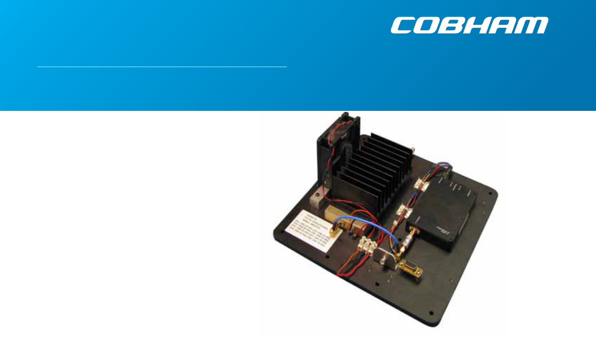
The Palladium 5000S is a small, modular
transmitter with a 5W RF power output. It’s
ideal for OEM concealments and short to
mid-range robotic and UAV applications. The
package is only 10” x 10” x 3.625”. All connec-
tions are conveniently located. The Palladium
5000S incorporates a power amplifier bring-
ing total power output to 5W.
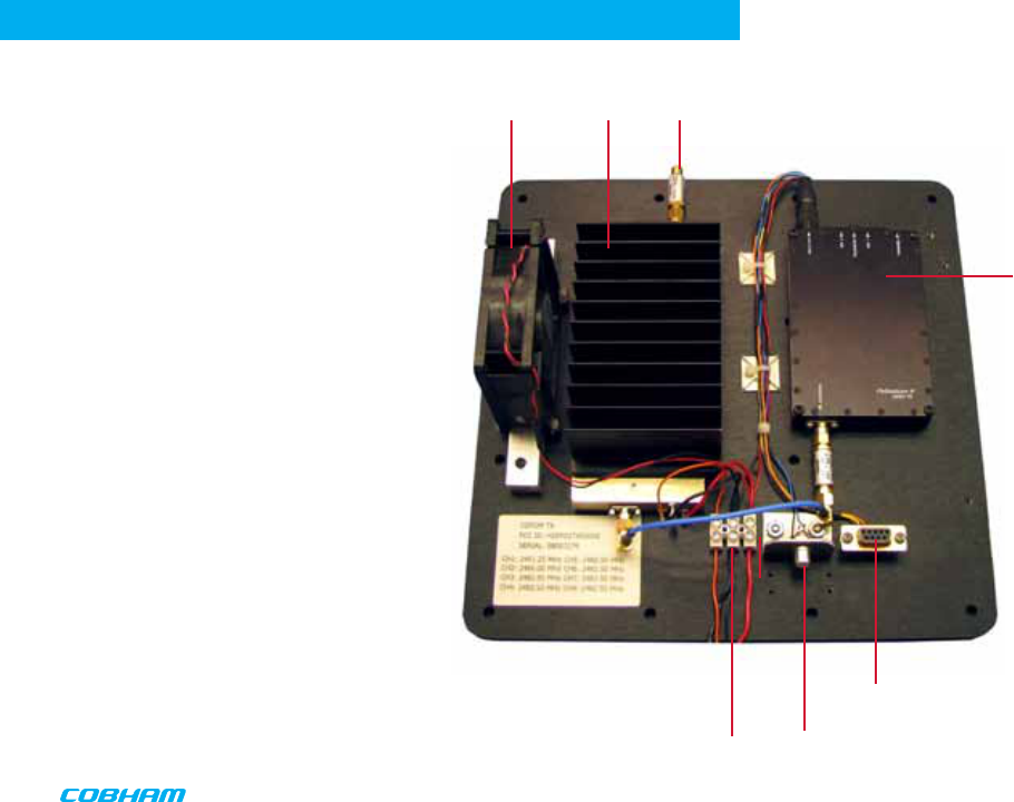
PD2
Transmitter
9 Pin Connector
NTSC Video Input
DC Power Input and
RF Output ON/OFF
control
Heatsink SMA Antenna connection
Fan
5
INTRODUCTION
Using your Palladium II Transmitter
Follow the instructions given in the Quick Start section on pages 6-7. When power is first ap-
plied to the Palladium, the unit reverts to the indicated channel and RF ON state. The Alarm LED
may be ON, which indicates that there is no active video input.
Changing your Transmitter Configuration
The Palladium Transmitter can store up to 8 different configurations, which can be selected
with the Channel Control. The frequency channels are preprogrammed please contact your
local Sales Manager for more information
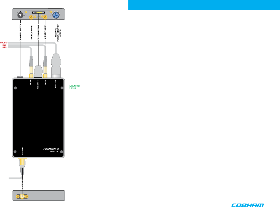
Top Controls/Connectors
• Multi-I/O Connector
• Data Chaining & Control Connector.
• Audio 2 (left) and Audio 1 (right/mono) LEMO Conn. These connectors provide the audio
input connections to the transmitter. Either one or two audio inputs can be used with the Pal-
ladium II Transmitter.
• Frequency Channel Controller
- Fmin = 1 (2451.25 MHz)
- Fmid = 2 (2466.00 MHz)
- Fmax = 3-8 (2482.50 MHz)
Bottom Controls/Connector
• SMA Antenna connection
6
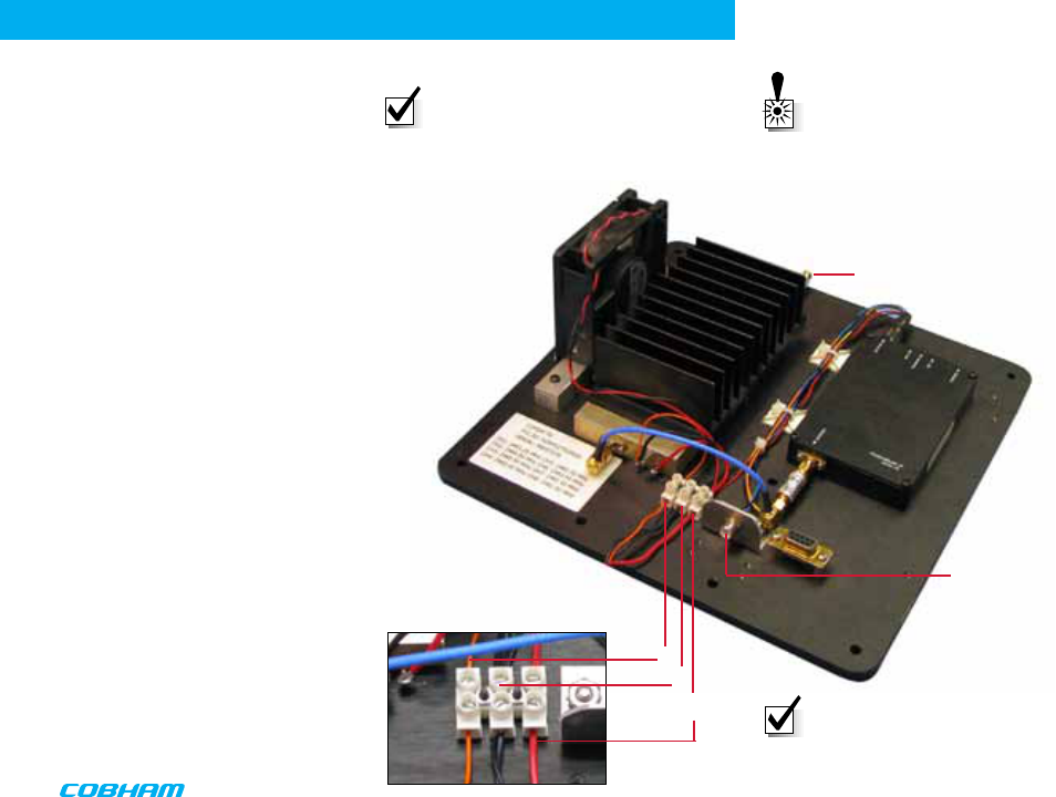
QUICK START
Complete these steps:
1. Connect the transmitter antenna to the
SMA connector on the Palladium unit
(see photo right).
2. Attach a 12 VDC power source (capable
of 7 amp output current) to the power block
(red) as shown to the right. The input voltage
is 12 VDC nom.
3. Connect a TTL logic source to the power
block (orange) as shown to turn on the
amplifier. This is the ON/OFF control for the
RF amp.
RF/ON = TTL1 RF/OFF = TTL0
4. Attach the common return of both supplies
to the (black) power center block
5. Attach your camera video input (75 ohm
composite video source in PAL or NTSC) to
the video RCA connector (see photo to the
right).
6. Apply the necessary power to your camera
and turn ON.
1
5
2
34
NOTE: Palladium TX-5000A Modules
feature a heat sink for proper heat
dissipation. For optimal performance,
do not block air flow over the fins of
this heat sink.
NOTE: Device is polarity sensitive.
Connect DC power only as shown
above; black to black (-), red to red (+).
WARNING: Do not connect the
antenna without a suitable 50
ohm load attached. The maxi-
mum safe operating distance,
antenna to human body must
be 30cm.

7
Physical
Unit Dimensions (approx.) 10 “ x 10” x 3.625 (not including connectors)
Environmental
Operational Temp -30 degrees C to 50 degrees C
Power
Input Voltage 12 VDC nominal
Power Consumption 75w
Control
PC Control Interface RS-232.
Memory 8 configurations
3 Factory programmed frequencies
Video Encoding
Compression Standard MPEG-2 w/ non-DVB modes, MPEG-4
DVB-T Compliant
Chrominance Profile 4:2:0
Line Standard PAL 625 or NTSC 525
Horizontal Resolution 704, 528, 480, 352 pixels (528 as standard)
Vertical Resolution 576 (625 lines) or 480 (525 lines)
Video Bitrates 1Mbps to 10 Mbps
Video Latency End to end delay of 54 milliseconds
SPECIFICATIONS

8
Audio Encoding
Input Stereo or Dual Mono pair
Bitrates 28 kbps to 72 kbps depending on configuration
Sampling Frequency 32 kHz, 16 kHz or 8kHz
THD < 0.1% max
Response 20Hz to 15KHz, +/- 0.25dB depending on
configuration
Crosstalk > 55 dB min
S/N 60 dB RMS
Composite Video Input
Standards NTSC (with and without pedestal) or PAL
Specification Rec. ITU-R BT.470-4
Connector Hirose
Composite PAL and NTSC decoding Eight-bit comb filtering composite decoder
Analog Audio
Analog Audio Input +10 dBu
Nominal Level +4 dBu
Scrambling
Scrambling type Fixed key scrambling system
Algorithms offered include AES.
COFDM RF output
Output Frequency Band Dependent
Occupied Bandwidth 2.44 MHz
Power 5000 mW
Connector SMA
COFDM Standard Proprietary, 2.5 MHz channel bandwidth
SPECFICATIONS

9
NOTES

10
NOTES

11
CONTACT USCONTACT US
486 Amherst Street • Nashua, New Hampshire 03063 • 603-880-4411 www.cobham.com/tcs
Cobham Tactical Communications and Surveillance