DTC Communications RCT1 Remote Switch Encoder and Receiver User Manual Switch Receiver Module
DTC Communications Inc. Remote Switch Encoder and Receiver Switch Receiver Module
Manual

DESCRIPTION: OPERATION MANUAL,
RCT-1 SWITCH TX ENCODER AND
RCR-2 SWITCH RECEIVER MODULE
ECO NUMBER: _______
Page ______of_______
Date: ______________
Orig.: ____________
SIGN OFF DATE: mm/dd/yy
Proj. Eng._________________
Prod. Eng._________________
Mfg. Mgr. _________________
Documentation ____________
Eng. Mgr._________________
Purchasing _______________

01/08/02
RCT-1 Switch Encoder and RCR-2 Switch Receiver Module
Detailed operating instructions, frequency and code options.
Encoder
The purpose of the RCT-1 Switch Encoder and RCR-2 Switch Receiver Module is to remotely activate
audio transmitters, recorders, camera, encryption, and microwave video transmitter packages via a secure
wireless link at distances up to 100 Meters. The handheld encoder is a license-free, Part-15 battery operated
device with an integral rubber duck antenna. The low power 900 MHz signal is digital FSK modulated and
digitally coded for security.
Switch Receiver
The miniature switch receiver unit, which detects this signal, is typically inserted between a power source
like a battery pack and a load. Voltages as high as 30 VDC at 2 Amps or 117 VAC at ½ Amp can be
switched.
The control signal from the RCT-1 is also digitally coded with an 8-bit user selectable address. Seven user-
selectable channels in the 902-928 MHz band are made available. This band was selected because it is
likely to be different from the frequencies used in the audio transmitter or microwave video link, thus
reducing the possibility of interference from these transmitters.
As configured from the factory, the switch receiver unit provides a dry switch closure. The small antenna
provided must be attached to the connector located on the module. Range extension can be accomplished
by locating the unit as high and in the clear as possible with the antenna in a vertical orientation. External
antennas such as standard 900 MHz GSM cellular vehicular antennas are also useful.
Security
The digital bitstream which includes the ON and OFF bits is encoded. 7 channels in the 902 –928 MHz
band are available and these are user –selectable via a rotary switch located on the PCB, by removing the
cover. The receiver must be pre-set to the same channel as the handheld encoder.
Channel Frequency
0 903.370
1 906.370
2 907.870
3 909.370
4 912.370
5 915.370
6 919.870
7 921.370
In addition to matching the channel setting, the 8 security address bits of the receiver must exactly match
that of the encoder. The security address bits are set via a dip switch on the PCBs.
Independent ON and OFF Commands
The control signal is of very short duration (< 5 seconds) and is intermittent in nature. That is, it only needs
to be sent once for turn on or turn off. Rather than a simple toggle state system, independent ON and OFF
commands are recognized. This eliminates the problem of not knowing or remembering what the last state
the receiver was in.
The command buttons (VIDEO ON and VIDEO OFF) should be pressed for a minimum of 2
seconds. ALWAYS TEST THE SYSTEM TO ASSURE THAT THE ENCODER AND SW
RECEIVER ARE SET PROPERLY AND FUNCTION BEFORE DEPLOYMENT.
1
01/08/02
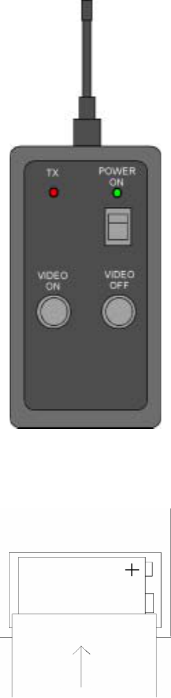
RCT-1 Handheld Encoder
The Handheld Encoder is a remote control transmitter, which provides secure short-duration command
signals for the Switch Receiver module. When used in conjunction with a properly deployed switch
receiver, a range of more than 100 Meters is available (note: the antenna is not removable). The signal
duration and power output of the handheld encoder is extremely low and the transmission is digitally
encoded. The size of the units is 5.0 X 2.75 X .75 Inches plus 3 Inches for the antenna.
Always start with a fresh Alkaline or Lithium 9VDC battery. The battery compartment may be accessed by
pushing down and back on the battery door and removing it. Insert the battery as shown:
BATTERY REPLACEMENT
2
01/08/02
Controls
The front panel of the RCT-1 has three switches and two LED indicators:
ON-OFF This switch applies power to the device. When ON, the green LED will illuminate.
VIDEO ON This momentary pushbutton sends the switch closure command (ON).
VIDEO OFF This momentary pushbutton sends the switch open command (OFF).
RED LED – This indicator will blink during the ON and OFF command transmissions indicating that data
is being sent.
The command buttons (VIDEO ON and VIDEO OFF) should be pressed for a minimum of 2
seconds. Do not be afraid to send the command signal several times while changing position or
closing the package, if the receiver does not initially respond. ALWAYS TEST THE SYSTEM TO
ASSURE THAT THE ENCODER AND SW RECEIVER ARE SET PROPERLY AND FUNCTION
BEFORE DEPLOYMENT.
Keep the unit turned OFF when not in use.
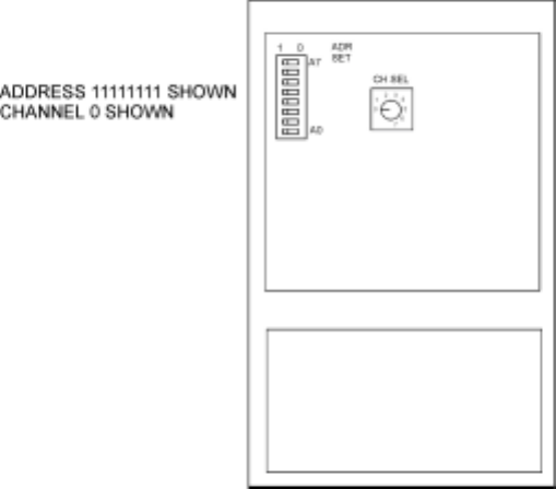
Changing Channels or Address Code bits
The Channel and 8 Address Bits in the handheld encoder must be set to agree with the Switch Receiver
module code settings to allow control to occur.
To access the board for channel and address bit settings changes, first remove the battery door and the
battery and then the four Phillips head screws on the rear of the unit. Carefully split the two halves and
access the switches, being careful not to break or stress the wiring. After switch setting, re-mate the halves;
replace the four screws and the battery and battery door.
3
01/08/02
Note: When this transmitter is operated in countries outside the USA with a 900 MHz GSM network,
channels 5, 6 and 7 are preferred, since they fall between the TX and RX cellular band segments.
Channel Frequency
0 903.370
1 906.370
2 907.870
3 909.370
4 912.370
5 915.370
6 919.870
7 921.370
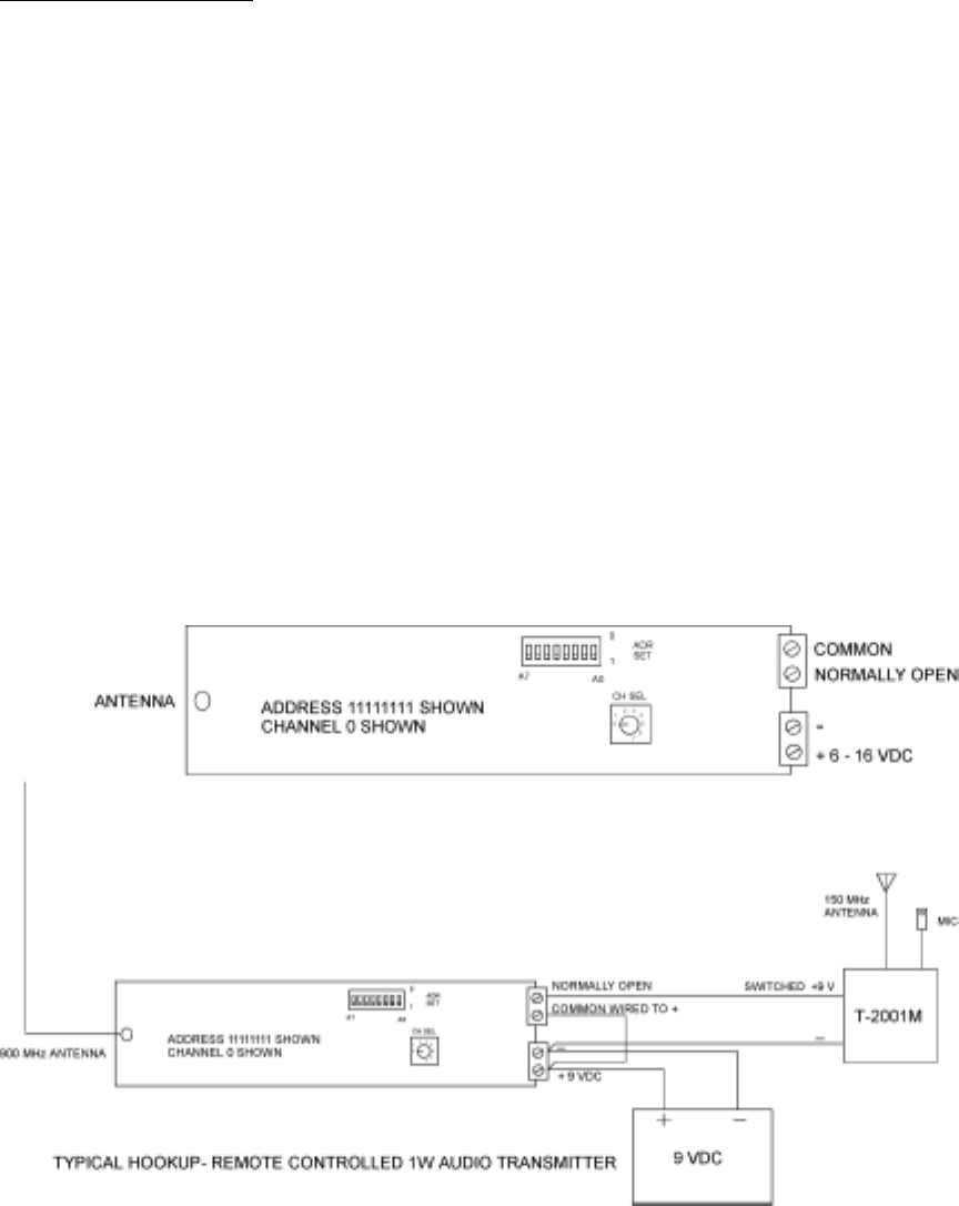
RCR-2 Switch Receiver Module
The RCR-2 (Remote Control Receiver) can be operated from 6 to 16 VDC and draws less than 20 mA in
all modes. It is equipped with an antenna, and two screw terminal blocks, one for external DC power and a
block for the normally open relay contacts. A small “noodle” antenna, equipped with an MMCX connector,
is provided with the receiver. The size of the unit is 5 X 1 X ½ Inches.
The hookup diagram shows a typical application; the RCR-2 controlling a 1 watt audio surveillance
transmitter, both SHARING a single power supply. The battery pack should be designed to support both
the ON time of the 1 Watt transmitter and the standby current of the switch receiver over the operational
period. Separate power sources may also be employed.
4
01/08/02
5
Latching Relay Feature
The Switch Receiver Module controls the power to the system via a latching type relay. This relay does not
require power to remain in the last state that it was set to. That is, if it was set to provide power and the
power source is removed, the relay remains latched.
Power On Reset
When the Switch Receiver Module is initially powered or is power is removed for 5 second or more and it
is reapplied (attaching a rechargeable battery for instance), the relay will automatically default to the OFF
or OPEN state.
Standby Operation / Operating Life
When the Switch Receiver Module is in the OFF state, only the receiver module is drawing current. This
drain is typically less than 20 mA. With a fully-charged 2 Ampere–Hour battery, the unit could remain in
standby for two days (48 Hours) and still provide more than 1 hour of video transmission.
Controlling Other Devices
The unit, as configured from the factory, provides a switched dry contact normally open set of contacts.
These contacts are closed when the ON command is received. Any external voltage up to 30 VDC at 2
Amps or 117 VAC up to 0.5 Amps can be controlled. Normally open (N.O.) contacts have been brought
out to the terminal block.
Changing Channels or Address Code bits
The RCR-2 channel switch and address switch may be accessed by first removing power and unscrewing
the four flathead Phillips screws holding the ABS case to the standoffs. The ABS housing will fall off
revealing the circuitry. The figure above shows the location of the channel and address switches. After
setting the switches, replace the cover and screws.
FCC Information:
DTC Communications, Inc.
75 Northeastern Blvd.
Nashua, NH 03062
Model RCT-1
FCC ID: H25 RCT1
This device complies with Part 15 of the FCC Rules.
Operation is subject to the following two conditions:
1. This device may not cause harmful interference.
2. This device must accept any interference including
interference that may cause undesired operation.