DTC Communications T2071 Surveillance Transmitter for Law Enforcement User Manual T2071M
DTC Communications Inc. Surveillance Transmitter for Law Enforcement T2071M
NEW MANUAL

DTC COMMUNICATIONS INCORPORATED
Derringer
Audio Transmitter
T-2071-M

2 OP1920175 Rev 1
How to contact DTC
For operator and troubleshooting
information, customers are encouraged to refer to
the details in this manual. For additional
clarification or instruction, or to order parts,
contact DTC.
Customer Service is available Monday through
Friday between the hours of 9:00 AM and
5:00 PM EST at:
1-800-233-8639
Tel: 603-880-4411
Fax: 603-880-6965
Website: www.dtccom.com
Email: info@dtccom.com
486 Amherst Street
Nashua, New Hampshire 03063
USA
Copyright Notice
Copyright © 2003
DTC Communications, Inc. All rights
reserved. No part of this document may be
reproduced, transmitted, transcribed, stored in a re-
trieval system or translated into any
language or computer language, in any form or by
any means, including but not limited to electronic,
magnetic, mechanical, optical, chemical, manual or
otherwise, without the prior written permission of
DTC Communications, Inc.
Disclaimer
The information in the document is subject to change
without notice. DTC makes no representations or
warranties with respect to the contents hereof, and
specifically disclaims any implied warranties of mer-
chantability or fitness for a particular purpose. DTC
reserves the right to revise this publication and to
make changes from time to time in the content hereof
without obligation of DTC to notify any person of such
revision or changes.
Trademarks
Trademarks of DTC Communications, Inc. include:
• DTC
• MiniPIX®
• DynaPIX®
Other product names used in this manual are the
properties of their respective owners.
Warranty
DTC warrants its manufactured components against
defects in material and workmanship for a period of
two (2) years, commencing on the date of original
purchase.
Products manufactured by others that are approved
for use with DTC equipment are warranted for the
manufacturer’s warranty period, commencing from
the date of shipment from DTC.
FCC information
Forms can be obtained from the FCC on their
website at:
www.fcc.gov
You can also contact the FCC using their FAX back
service at: (888) 418-3676
Additional instructions are available by telephone at:
(888) 225-5322
The filing fee form is returned to:
Federal Communications Commission
1270 Fairfield Road
Gettysburg, PA 17325-7245
3
Manual Conventions
NOTE Describes special issues you should be aware
of while using a particular function.
WARNING Calls out situations in which equipment
could be damaged or a process could be incorrectly
implemented, but in which operator safety is not a
factor.
TIP Describes application hints.
TABLE OF CONTENTS
Overview ............................................................................. 4
Quick Start ........................................................................... 5
Tips ..................................................................................... 6
Connections ....................................................................... 7
Specifications .................................................................. 8-9
Programming .............................................................. 10-13
Accessories...................................................................... 14
Contact ............................................................................. 15
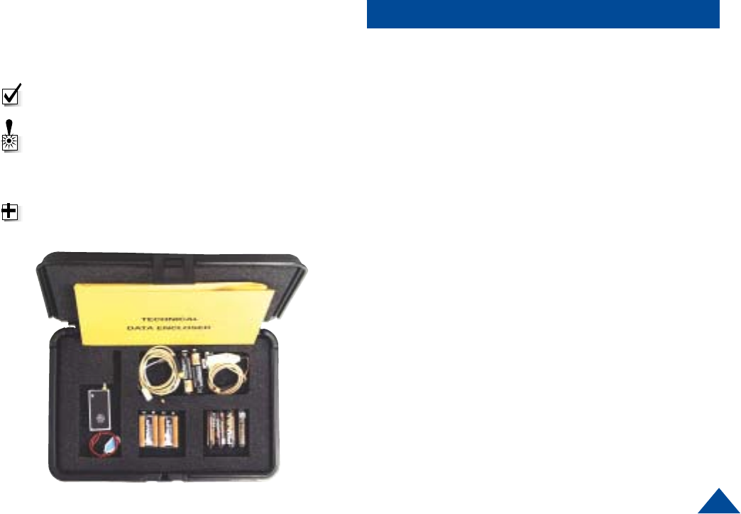
What should you expect to receive with your Derringer
transmitter?
• T2071-M Transmitter
• 2 9V Batteries
• 1 “AA” Battery Pack
• Programming Software kit with programming cable
• 36" Microphone
• Noodle antenna
• Data sheet and 1 Operator’s Manual
• Screwdriver
4
OVERVIEW
The T2071-M Derringer is a small audio transmitter which
can transmit a secure and clear audio signal. It has up to 10
programmable channels for the RF transmission,
accessed through a PC with DTC programming software
installed. The transmitter is designed for personal protec-
tion and evidence gathering missions. Its miniature size
and rugged design ensures safe concealment and long-
lasting performance. The frequency is programmable for
narrowband (TIA/EIA 102 compliant) or wideband operation.
These parameters may be saved in memory. The Derringer
has a built-in internal microphone, the abilty to use an 36”
external microphone, and built-in scrambler.
Channel Programming Includes
• Frequency
• AGC (Automatic Gain Control) On/Off
• Width (Narrow / Wide band)
• Scrambled / Clear Signal ON/OFF
Note: Do not operate the transmitter without the
noodle antenna installed.
NOTE: To prevent unwanted interference keep the
microphone and the noodle antenna separated.
Do not allow them to come into contact with each
other.
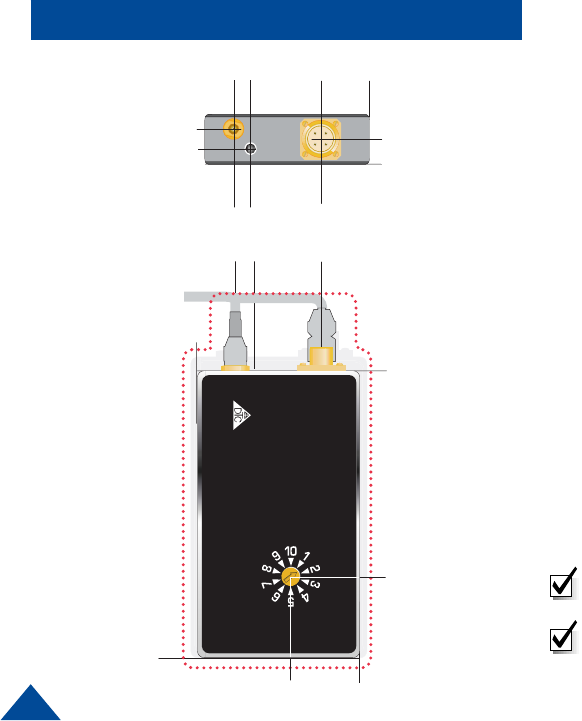
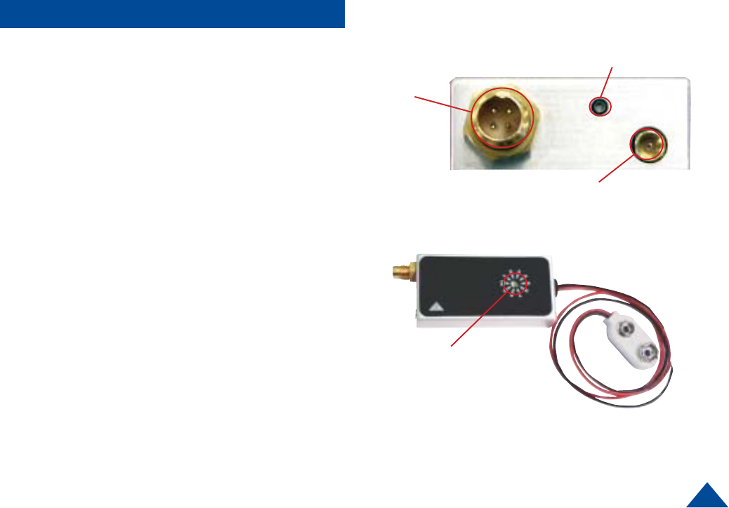
Top View
Front View
Using The Derringer
.250
.000
.420
.200
.313
.313
.1
4
5
.145
.
21
0
.210
.
625.625
1.1
00
1.100
.590
.590
000
000
.000
.000
.000
.000
.
2.14
0
.2.140
MULTI-PIN
CONNECTOR/
EXTERNAL
MICROPHONE
ANTENNA
INTERNAL
MICROPHONE
5
QUICK START
PROCELL
DURCELL
43
1
2
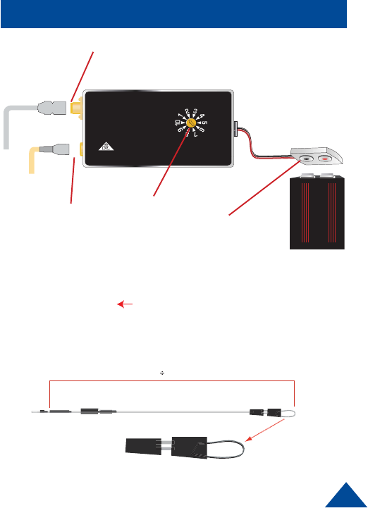
Using A Separate Microphone
1Install the 36” microphone into the microphone
connector on the transmitter.
2Install the noodle antenna into the antenna connector
on the transmitter. Adjust length according to band of
operating frequencies.
3Attach fresh batteries to the snap on connector.
4Using a small screwdriver, turn the recessed rotary
switch located on the front cover to the desired
channel. The configuration of each channel is
managed with DTC programming software. The
programming software included with your Derringer
allows you to assign frequencies, and set the
deviation.
The NOODLE ANTENNA
The “noodle” antenna may be adjusted over the frequency
range of 138 MHz to 174 MHz by adjusting the amount of wire
that is folded back along side the end of the antenna. Use
heatshrink tubing to hold the adjusted length.
The total length may be calculated by the following formula.
Length (inches) = 2950 / (Freq MHz)
Example:
CH1: 150.000
CH2: 151.000
CH3: 152.000
Center of operating frequency
Length (inches) = 2950/151
Total length = 19.5"
Length
Loop
2950 151 = 19.5
6
TIPS
34
Battery Operation:
Always remove battery when not in use. It is imperative to
discard partially used batteries, as their remaining life is not
predictable. Always start an operation with fresh batteries.
Audio Circuit and Body Mounting Tips:
All body-worn transmitters are susceptible to “clothing noise”.
Reducing this rubbing effect is accomplished in a variety of ways.
Secure the transmitter to the body with an ace bandage or a custom
harness.
1Try to locate the microphone in an area where “pickup” will be
best and rubbing noise is least. Avoid the arms, legs, crotch,
under the arms or waist area. Front torso mounting is ideal.
2Always provide a small amount of strain relief on the micro
phone cable itself. This reduces the noise caused by the
microphone cable and element being tugged and prevents
cable damage.
3Secure the microphone cable to the body with medical adhesive
tape in at least two spots, the final being about an inch below the
element. Remember to leave a strain relief loop!
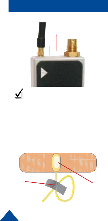
4Completely cover the microphone element (facing outward) with
an ordinary Band Aid™. This provides a damped baffle for the
microphone and a slick surface for clothing to rub on, and
actually does not impact audio pickup level at all.
Note: This is a push-on, pull off
locking connector. The connector
will rotate 360° in the transmitter
without disconnecting. Use
extreme caution when connecting
or removing the noodle antenna.
To remove pull the noodle antenna
straight out.
PULL UP ON SECTION INDICATED
TO RELEASE LOCK AND REMOVE
7
Antenna Connector
Multi Pin
Connector
Top View
CONNECTIONS
Microphone
Front View
Channel Select
Switchable
ANTENNA (Male MMCX Connector)
This connector accepts the noodle antenna.
MICROPHONE
The Derringer uses an internal electret microphone in addition
to an external microphone
MULTI-PIN CONNECTOR (Male multi-pin connector)
This connector mates with the 36” external microphone and
also mates with the programming cable and optional vehicular
power adaptor model VPA-2001.
CHANNEL SELECT SWITCH (Rotary Switch)
The channel select switch allows you to change transmit
channels and is located on the front of the transmitter. It is a
rotary switch which requires the use of the supplied screw-
driver to turn the switching mechanism. Select a transmit
channel number by turning the rotary switch. The configuration
of each channel is managed with DTC programming software.
The programming software included with your Derringer allows
you to assign frequencies, set the deviation, turn ON/OFF
scrambler mode, and turn ON/OFF AGC.
8
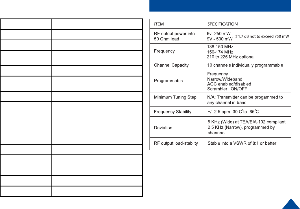
SPECIFICATIONS
The Derringer measures just 2.1” by 1.1” by .4”; it provides
ten user programmable channels and audio scrambling.
Automatic gain control is programmable by channel as well.
The Derringer contains an internal microphone, which is
automatically disabled if an external microphone is at-
tached. Power is provided by a convenient snap-on 9 Volt
battery type connector.
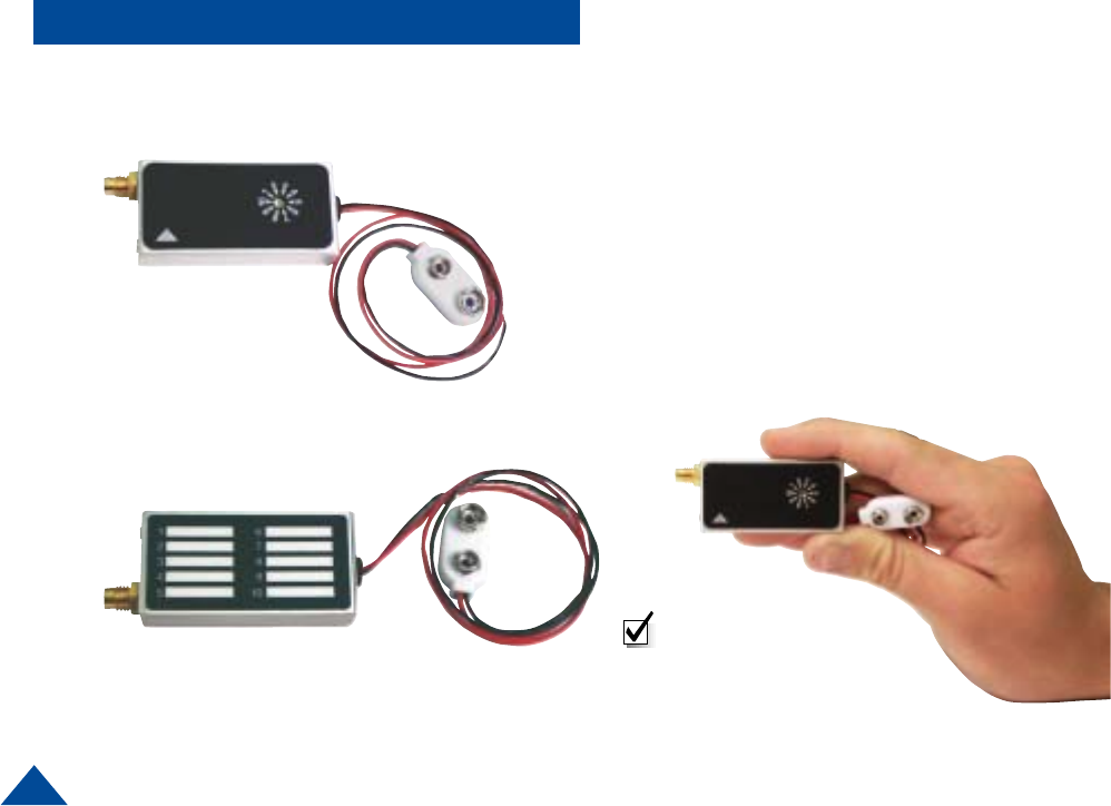
The back cover of the Derringer allows an individual to use
a pencil to write down the frequency for each channel, as a
quick reference guide.
Front Cover View
Back Cover View
Note: Consider using a
designator for your
frequency, such as “A” or
“Blue”. If you lose control of
the transmitter you won’t
compromise your frequency.
9
SPECIFICATIONS
ITEM SPECIFICATION
AGC Range 45dB
Microphone Electret-fet internal or external
Spurious & Harmonics -50 dBc max non-harmonic, -45 dBc
harmonic
Operating Temp Range -30° C to +70° C
Operating Voltage
Range 6.0 to 9.0 VDC
Controls 10 channel recessed rotary switch
Connectors
RF output to antenna - MMCX
Multi-pin Telocate (JT4MB -00)
Pin 1 - Audio from external microphone
Pin 2 - RS-232 serial input
Pin 3 - RS232 serial output
Pin 4 - external power
Shield - ground return
Power Sources External
NOTE All specifications at 25° C and R/F
measurements taken into 50 Ohms unless
otherwise noted
NTIA Compliant TIA/EIA- 102 - analog mode
Dimensions 2.10" W x 1.1" H x .043" D
10
PROGRAMMING
Introduction
When you order a Derringer audio transmitter, DTC will factory program your
frequencies at no additional charge to you. You may want to place a sticker over
the rotary switch on the chassis so users in the field don’t attempt to change
frequencies. This is often the best path for state and local agencies with limited
frequencies available to them.
DTC will also provide you with free software and a free programming cable,
enabling you to change your transmit frequencies.This is ideal if you often work
with other agencies, or anticipate the equipment being used by a multi-jurisdic-
tional task force. You can program up to ten channel settings per unit. In general,
this allows you to program most variations you might encounter in the field at the
depot level. You will be able to program frequency, narrowband/wideband, AGC
enabled/disabled and scrambler ON/OFF.
As a practical matter, your Derringer transmitter’s frequencies will be dictated by
the frequency of your receiver and/or repeater. In many cases, these devices are
crystal controlled or have few channel options.
TIP: Make sure that you program your transmitter to match the frequencies
of your receiver, and test the components as a system prior to going into
the field!
11
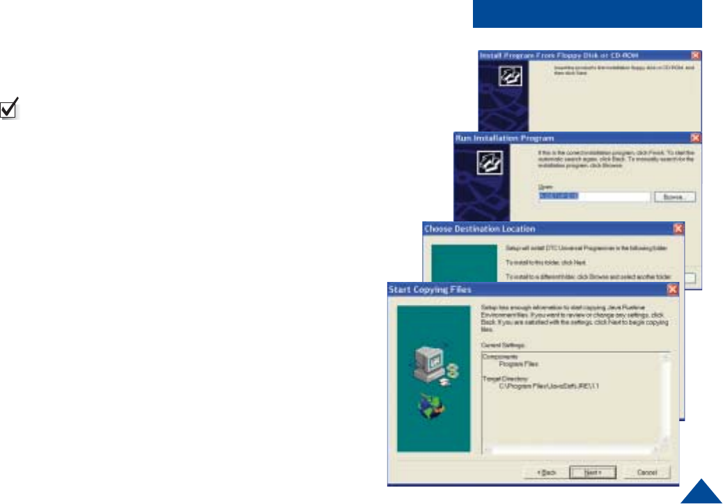
PROGRAMMING
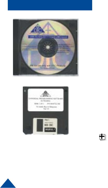
Installing DTC Universal Programming
Software on your PC
NOTE: Uninstall any previous versions by going to Add/
Remove Programs, clicking on DTC Universal Pro-
gramming, and clicking on uninstall.
1Click on Start, click on run.
2Click on the Browse button.
3Click on or find your CD drive.
4Install the JAVA Runtime Environment Application first
(CD provided).
5Follow the install wizard screens.
6Install the Universal Programming software next (floppy
provided).
7Click on Start, click on run.
8Click on the Browse Button.
9Click on your floppy drive.
10 Double click on the setup.
11 Follow the install wizard screens.
Your programming software is installed
12
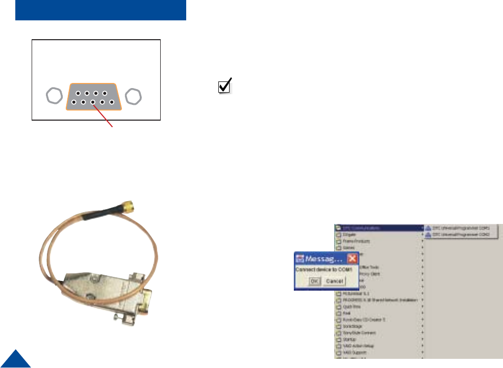
PROGRAMMING
COM1 or COM2
Serial port of computer
1Check that an antenna (or non-radiating load) is connected to the Derringer
MMCX antenna port.
2Connect the DB9 end of the DTC programming cable to either the COM1 or
COM2 port of the PC depending on port availability.
Note: A 6-foot extension cable may be used between the PC and the DTC
programming cable.
3Plug the round 4-pin connector end of the DTC programming cable into the
Derringer multi-I/O connector. Rotate the cable plug until the connector can
be felt to align properly. At this point push the connector in and screw the
retaining sleeve until snug
4Check that the Derringer has a battery power installed with proper polarity
orientation.
5On the PC, mouse-click on Start, Programs, DTC Communications.
6You will be prompted to select either COM1 or COM2.
7Select the desired port as defined in Step 2.
Connect the serial end of the
programming
cable here
13
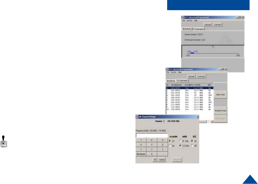
PROGRAMMING
8Mouse-click OK or cancel.
9Now follow the instructions on the DTC Programming Application to begin
the download and subsequent frequency reprogramming process.
Select the channel number you want to edit
Click Edit Chan
Input the frequency using key pad on window or keyboard numbers
Set scramble options
Set AGC (Automatic Gain Contol) options
When done, click OK-if no change is desired, click CANCEL
When all programming edits have been completed, select UPLOAD to
transfer your new settings to the Derringer.
Your Derringer is now programmed.
10 After successfully using the DTC Programming Application, remove the
round 4 pin multi-I/O connector from the Derringer by unscrewing the
retaining sleeve on the connector “barrel”.
Warning: Do not disconnect the programming cable
until the programming operation (connect or Upload)
is complete.
14
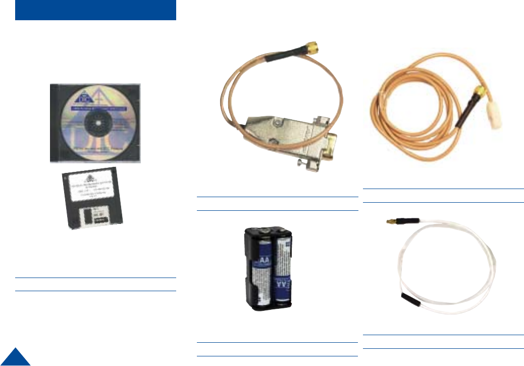
ACCESSORIES
Part Number Description
7011150 3’ Microphone
DTC Universal Programming Software
DTC part number 8002025
Part Number Description
4045319 Noodle Antenna
Part Number Description
4044738 Programming Cable
Part Number Description
4044377 4 “AA” Battery Pack

15
CONTACT US
Director of Federal Sales
John Morgan
toll free (800) 233-8639
voice (603) 546-2122
cell (603) 320-3257
fax (603) 880-6965
jmorgan@dtccom.com
Federal Sales Manager
Marianne Caiazza
toll free (800) 233-8639
voice (603) 546-2121
cell (603) 320-3256
fax (603) 880-6965
mcaiazza@dtccom.com
Federal Sales Manager
Wireless Video Products
John Robey
toll free (800) 233-8639
voice (703) 878-4375
fax (703) 680-7997
cell (571) 217-0599
pager (877) 468-1764
jrobey@dtccom.com
Sales Representatives
National Sales Manager
State & Local Agencies
Michael Demos
toll free (800) 233-8639
voice (603) 546-2120
cell (603) 320-3255
fax (603) 880-6965
mdemos@dtccom.corn
Inside Sales
Federal/International
Steve Chisholm
toll free (800) 233-8639
voice (603) 546-2124
fax (603) 880-6965
schisholm@dtccom.corn
International Sales Manager
Juan Alfonso
voice (603) 546-2126
cell (978) 505-1745
fax (603) 880-6965
jalfonso@dtccom.com
Surveillance Platforms
IST
toll free (888) 478-6599
voice (954) 755-0724
cell (954) 755-0817
teamist@aol.com
Canada
Dyplex Communications LId.
Gary Sayer
voice (416) 675-2002
tax (416) 675-1822
info@dyplex.com
REGIONAL SALES MANAGERS
Howard Rich
toll free (888) 819-8570
voice (860) 626-8570
fax (860) 626-8571
NY, MA, CT, RI, PA, NJ, MD, DE
hrich@dtccom.com
Gary Nichols
toll free (866) 794-2823
voice (765) 473-8917
fax (765) 473-8920
MN, WS, MI, IA, MO, IL, IN, OK, KY
gnichols@dtccom.com
Floyd Flowers
voice (208) 667-5197
fax (208) 769-9387
WA, OR, ID, MT, ND, WY, UT, SD
Joe Parkinson
toll free (800) 952-4914
voice (909) 598-5110
fax (909) 598-3120
CA, AZ, NV, HI, AK
jparkinson@dtccom.com
Tim Scally
toll free (877) 860-9096
voice (817) 368-9830
fax (817) 281-0453
TX, OK, AR, LA, NM, KS
tscally@dtccom.com
Frank Prioli
toll free (800) 246-2610
voice (727) 392-4761
fax (727) 320-0509
FL, GA, AL, MS, TN, NC, SC
fprioli@dtccom.com

486 Amherst Street • Nashua, New Hampshire 03063 • 603-880-4411
www.dtccom.com
486 Amherst Street • Nashua, New Hampshire 03063 • 603-880-4411
www.dtccom.com