DTC Communications T2350 T-2350 1Watt Audio Transmitter User Manual T2300manual 2
DTC Communications Inc. T-2350 1Watt Audio Transmitter T2300manual 2
Users Manual
DTC COMMUNICATIONS INCORPORATED Draft
T-2350-1Watt
Audio Transmitter
PrPr
PrPr
Project 25 Digital & Analogoject 25 Digital & Analog
oject 25 Digital & Analogoject 25 Digital & Analog
oject 25 Digital & Analog
Users ManualUsers Manual
Users ManualUsers Manual
Users Manual

How to contact DTC
For operator and troubleshooting
information, customers are encouraged to refer to
the details in this manual. For additional
clarification or instruction, or to order parts,
contact DTC.
Customer Service is available Monday through
Friday between the hours of 9:00 AM and 5:00 PM
EST at:
Tel: 603-880-4411
Fax: 603-880-6965
Website: www.dtccom.com
Email: info@dtccom.com
486 Amherst Street
Nashua, New Hampshire 03063
USA
Copyright Notice
Copyright © 2004
DTC Communications, Inc. All rights
reserved. No part of this document may be
reproduced, transmitted, transcribed, stored in a re-
trieval system or translated into any
language or computer language, in any form or by
any means, including but not limited to electronic,
magnetic, mechanical, optical, chemical, manual or
otherwise, without the prior written permission of
DTC Communications, Inc.
Disclaimer
The information in the document is subject to change
without notice. DTC makes no representations or
warranties with respect to the contents hereof, and
specifically disclaims any implied warranties of mer-
chantability or fitness for a particular purpose. DTC
reserves the right to revise this publication and to
make changes from time to time in the content hereof
without obligation of DTC to notify any person of such
revision or changes.
Trademarks
Trademarks of DTC Communications, Inc. include:
• DTC
• MiniPIX®
• DynaPIX®
Other product names used in this manual are the
properties of their respective owners.
Warranty
DTC warrants its manufactured components against
defects in material and workmanship for a period of
two (2) years, commencing on the date of original
purchase.
Products manufactured by others that are approved
for use with DTC equipment are warranted for the
manufacturer’s warranty period, commencing from
the date of shipment from DTC.
Intellectual Property Rights
Notice
Digital Voice Systems, Inc. (DVSI) claims
certain rights, including patent rights under
US Patents #5,870,405, #5,826,222,
#5,754,974, #5,701,390, #5,715,365,
#5,649,050, #5,630,011, #5,581,656,
#5,517,511, #5,491,772, #5,247,579,
#5,226,084, #5,195,166, and under other US
and foreign patents patents and patents
pending, in IMBE Vocoder technology and
software embedded in this product. Any
use of this technology or software requires
a separate written license grant
from DVSI.
IMBE is a registered trademark of Digital
Voice Systems, Inc.
2
3
NOTE Describes special issues you should be aware
of while using a particular function.
WARNING Calls out situations in which equipment
could be damaged or a process could be incorrectly
implemented, but in which operator safety is not a
factor.
TIP Describes application hints.
Manual Conventions
Table of Contents
Overview ............................................................................. 4
Connections ...................................................................... 5
Quick Start Option 1 .......................................................... 6
Quick Start Option 2 .......................................................... 7
miniSDTM Card ................................................................. 8-9
Recording to a miniSDTM Card ......................................... 10
Trouble Shooting ...............................................................11
Tips................................................................................... 12
Specifications .................................................................. 13
Programming .............................................................. 14-16
Programming Options ................................................ 17-20
Encryption ......................................................................... 21
Accessories Antennas..................................................... 22
Warranty ............................................................................ 23
4
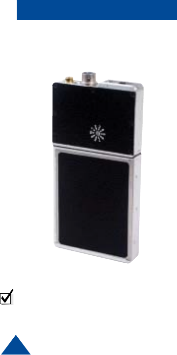
The T-2350 is a synthesized VHF, digital and analog audio transmitter with a
software selectable power output of 1 Watt. The T-2350 has an optional
removable Mini SDTM Card that can record approximately 1 minute of audio in
WAV file format per MB of storage.
The T-2350 has 10 programmable channels. It is designed for body worn
personal protection and evidence gathering missions. Its miniature size and
rugged design insures safe concealment and long lasting performance. The
time to half power with fresh AAA Alkaline batteries is 5 hours. The transmission
is programmable for digital P25 clear, digital P25 encrypted, analog
narrowband, or analog wideband operation. The T-2350 transmission is either
duplexed on the mic/antenna cable (meaning the microphone is the antenna)
or transmitted on a stand-alone noodle antenna, in which case the internal
microphone or remote microphone must be used.
Concerned with the rapid evolution of digital communication technologies and
a need for interoperability, the Association of Public Communications safety
Officials (APCO) developed an open architecture, digital standard for public
safety and government communications systems. Products compliant with
APCO Project 25 standard are interoperable, regardless of the manufacturer.
The National Telecommunications and Information Administration (NTIA) has
adopted the APCO Project 25 interoperability standard, also known as TIA/EIA-
102. The T-2350 is compliant with this standard.
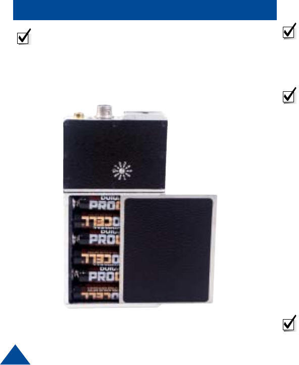
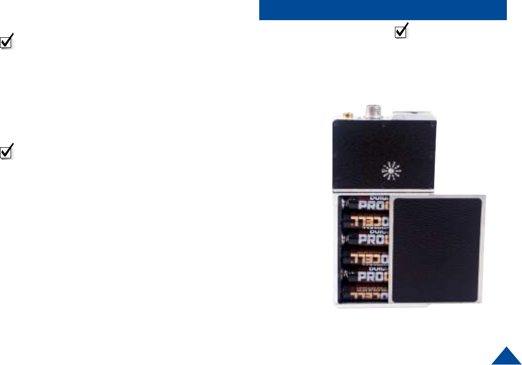
Overview
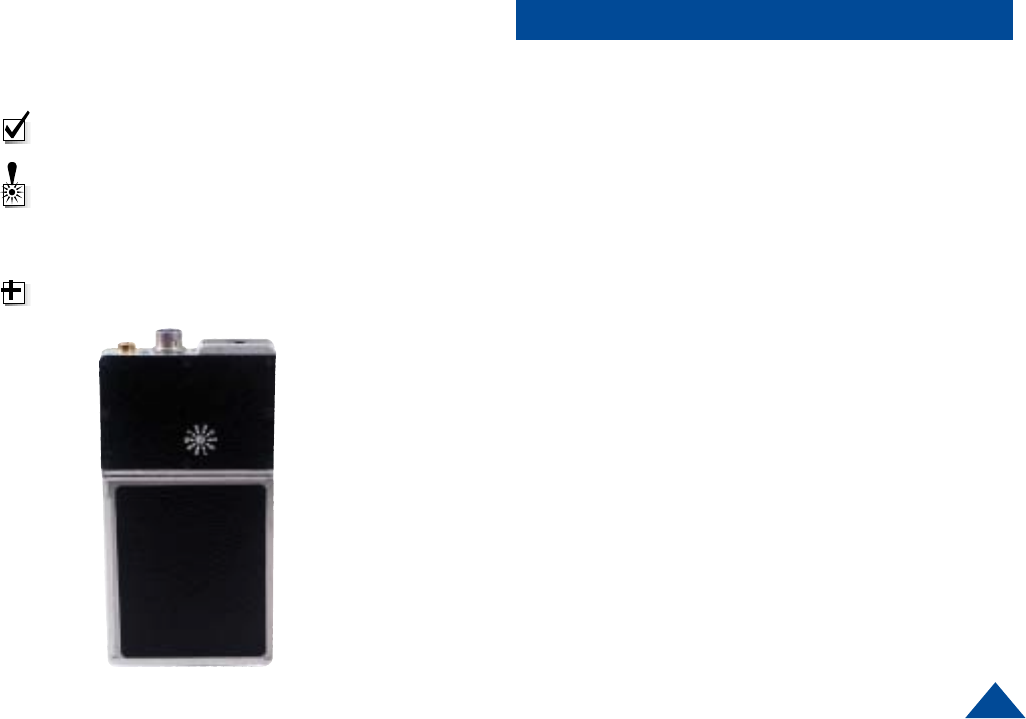
Front of Transmitter
Channel Select
Switch
Internal
Batteries
Back of Transmitter
miniSDTM Card
5
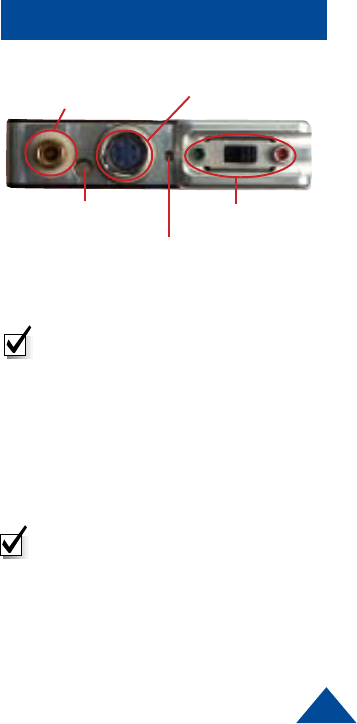
Connections
ANTENNA (Female Lemo Connector)
This connector accepts both the mic/antenna and the noodle antenna.
MULTI-PIN CONNECTOR (Male multi-pin connector)
This connector mates with an external microphone and is used in conjunction
with the noodle antenna. This connector also mates with the programming
cable.
STATUS LED
Once power is applied (after approximately 3 seconds), the Status LED will turn
on (green), which indicates a successful self-test. The LED will turn off after a
few seconds, and remain off or flash green at 1 second intervals. (See program-
ming section)
ON/OFF SWITCH (Slide Switch: Green dot is ON, Red dot is OFF)
The ON/OFF switch controls the power to the transmitter. The power is supplied
through the internal battery compartment, which holds six AAA batteries. Sliding
the switch to the green dot turns the power ON. Sliding the switch to the red dot
turns the power OFF.
CHANNEL SELECT SWITCH (Rotary Switch)
The channel select switch allows you to change transmit channels and is
located on the front of the transmitter. It is a rotary switch which requires the use
of the supplied screwdriver to turn the switching mechanism. Select a transmit
channel number by turning the rotary switch.
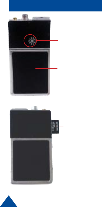
On / Off Switch
Multi Pin Connector
Top View
Internal Microphone
Status LED
Antenna Connector
NOTE: When Cycling power on the
unit, power switch must be left in
the off postion for at least 2
seconds before turning it back on.
NOTE: When using the noodle
antenna, the unit must be pro-
grammed to use the alternate
microphone. If no external
microphone is connected, the unit
will automatically use the internal
microphone.
6
QUICK START Option1 Using The Antenna/Mic AssemblyUsing The Antenna/Mic Assembly
Using The Antenna/Mic AssemblyUsing The Antenna/Mic Assembly
Using The Antenna/Mic Assembly
NOTE: The channel being used must be programmed
to use the antenna/mic
1Install the antenna/mic into the antenna connector
on the transmitter.
NOTE: This is a push-on, push off locking connector.
The connector will rotate 360° in the transmitter
without disconnecting. Use extreme caution when
connecting or removing the mic/antenna.(See
illustration on page 12.)
2Ensure that the power switch on the transmitter is set
to OFF. (Red dot is OFF).
3Slide the battery door to the right and install six, fresh
AAA batteries, being careful to observe proper polarity.
Slide the battery door to the left to close the battery
compartment.
4Using a small screwdriver, turn the recessed rotary
switch located on the front cover, to the desired
channel.
5Turn the unit on by sliding the switch to the ON
position. (Green dot is ON.)
NOTE: Once power is applied (after approximately 3
seconds), the Status LED will turn on (green), which
indicates a successful self-test. The LED will turn off
after a few seconds.
NOTE: Do not operate
the transmitter without
an antenna installed.
7
QUICK START Option 2
Using A Separate MicrUsing A Separate Micr
Using A Separate MicrUsing A Separate Micr
Using A Separate Microphone with theophone with the
ophone with theophone with the
ophone with the
Noodle AntennaNoodle Antenna
Noodle AntennaNoodle Antenna
Noodle Antenna
NOTE: The channel being used must be programmed
to use the internal mic.
1Install the 36” remote microphone into the auxiliary
(multi-pin) connector on the transmitter
2Install the noodle antenna into the antenna connector
on the transmitter. Adjust length to center of operating
frequencies. (See example on Page 22)
NOTE: This is a push-on, push off locking connector.
The connector will rotate 360° in the transmitter without
disconnecting. Use extreme caution when connecting
or removing the noodle antenna.(See illustration on
page 12.)
3Ensure that the power switch on the transmitter is set
to OFF. (Red dot is OFF).
4Slide the battery door to the right and install six, fresh
AAA batteries, being careful to observe proper polarity.
Slide the battery door to the left to close the battery
compartment.
5Using a small screwdriver, turn the recessed rotary
switch located on the front cover to the desired
channel.
6Turn the unit on by sliding the switch to the ON
position.(Green dot is ON.)
NOTE: Do not operate
the transmitter without
an antenna installed.
8
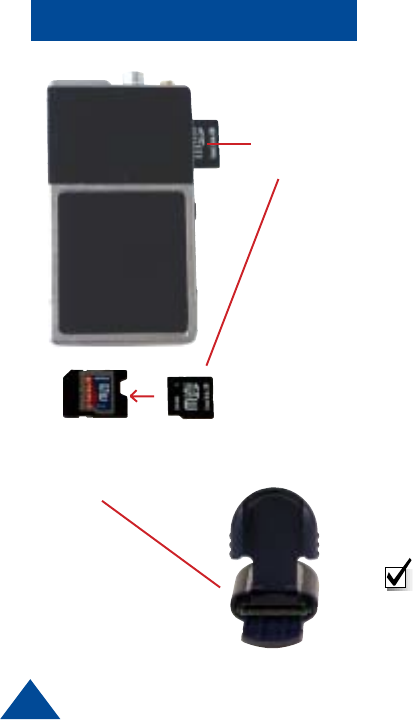
miniSDTM
Card
miniSDTM Card
Adapter (to be
used with Card
Reader)
miniSDTM Card
miniSDTM
Card
miniSDTM Card
The T-2350 uses an industry-standard miniSD™ card to make audio
recordings. A 512 MB card, an SD to miniSD adapter, and an SD card reader
are provided with a new T-2350. The audio is recorded in a Windows PCM
waveform format (.wav file). Should the need to replace the card arise, they can
be purchased at most major retailers in various densities from 32 Mb to
512 Mb. Higher densities may be available in the future. As an example, a 32Mb
card will provide approximatley 30 minutes of recording time, 64Mb wil provide
about 60 minutes, etc. The 512 Mb card included with the transmitter will
provide well over 8 hours of recording time. Generally speaking, 1 MB of
memory will provide about 1 minute of recording.
Every new miniSD™ must be properly formatted before it can be used.
Formatting is a simple process that can be done on almost any Microsoft
Windows equipped PC, Laptop, Notebook, and some hand-held PCs. Typically,
this will only need to be done once on each card.
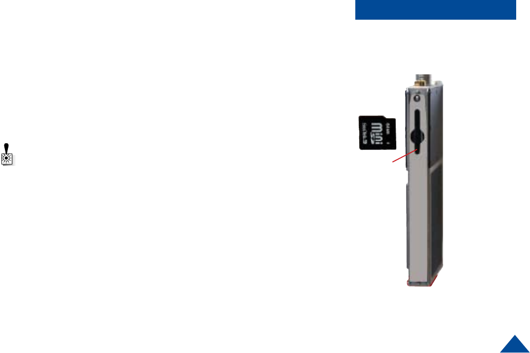
Installing miniSDTM Card
The miniSD™ card slot is accessed by sliding the side panel down (Figure 2).
The Card is inserted with the gold tabs facing the same side as the Channel
Switch. When installed, a red LED will be illuminated indicating that the card
should not be removed due to file management activity. Wait until the red LED
is OFF before removing the card by gently pushing in until it releases.
SD Card
Reader
NOTE: Never insert or remove the card while power is ON.
9
miniSDTM Card
miniSDTM
slot
Figure 2
Formatting Instructions for Desktop, Laptop, and Notebook computers.
1. Double click on ‘my computer’ to display your list of drives.
2. Insert the miniSD™ card into the miniSD™ to SD adaptor as shown.
3. Insert the adaptor into the SD card reader included with the
transmitter.
4. Insert the card reader into an available USB port on your computer.
The computer should acknowledge the installation by adding another
drive icon in the drive list called ‘Removable Disk’ and followed by a
drive letter.
5. Right click on this new drive, pick Properties, and then Format.
WARNING: Do not perform this function on any drive whose name or type is
“LOCAL DRIVE”. Doing so could permanently harm your computer.
6. Ensure that the ‘Quick Format’ and ‘Enable Compression’ boxes are
NOT checked, then click ‘Start’.
7. Click OK in the Warning box that appears. When the dialog box that
confirms that the format is complete appears, click OK. The format is
now complete and the miniSDTM card can be used in the T-2350.
Installing the miniSDTM card into the T-2350
1. Power OFF the T-2350.
2. Remove the aluminum cover plate access the miniSDTM slot.
3. Install the miniSDTM card so the gold fingers of the miniSDTM card will
face the same side as the Channel Select Rotary switch of the T-2350
transmitter.
4. Replace the aluminum cover plate
Side View of the miniSDTM slot
10
Recording to a miniSDTM Card
Each of the ten selected channels on the T-2350 can have the recording feature
turned on or off independently from each other. This is accomplished by
clicking the ‘recording on’ or ‘recording off’ button for each channel in the DTC
Universal Programming Software (refer to Figure 3 page 19 for details). To
make a recording, the desired channel must have the ‘recording on’ button
checked, and a properly formatted miniSD card with some available space
must be installed in the T-2350 miniSD slot. For the purposes of this tutorial,
the ‘recording messages’ radio button should be set to ON via the DTC
Universal Programmer.
1. Install a properly formatted miniSDTM card with some available space into
the T-2350, gold connectors facing the side with the channel switch, and
slide the door closed.
2. Set the channel switch to a channel with recording enabled.
3. Turn on a radio reciever tuned to a matching frequency.
4. Turn on the T-2350. First, a message broadcasting “Media Present With
More Than Four Hours Of Recording Time” will be heard on the receiver, then
a few seconds later you will hear the message “Recording Start”.
5. Speak into whichever microphone is enabled, allowing for the recording to
progress for a few moments
6. Set the power switch to the OFF position.
7. Ensure that the red LED in the card slot is NOT on, then push the card in to
remove.
8. Insert the card into the miniSD-SD adaptor, then insert the adaptor into the
reader.
9. Using Windows Explorer, open the SD card and double click on the newly
created .wav file. This should launch the application that plays audio files.
10. Ensure the PC speakers are turned on and at a comfortable listening level.
The recording you just made should now be playing.
NOTE: Pre-recorded messages are
broadcast but not recorded.
Recording
11
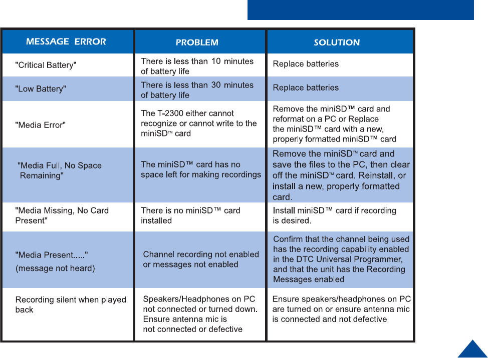
Trouble Shooting
12
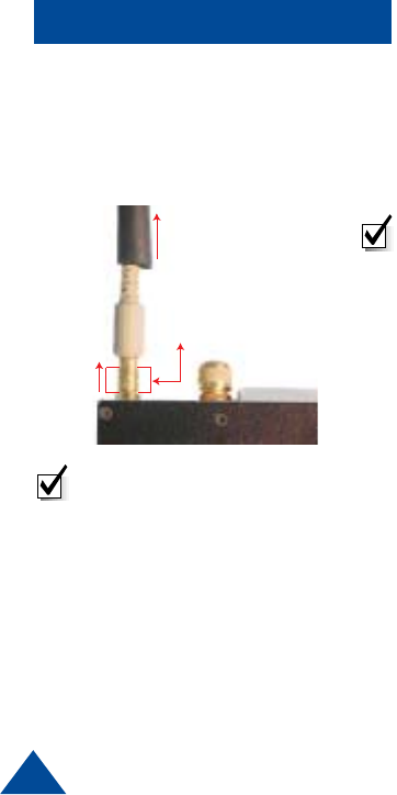
Tips
SLIDE BLACK SLEEVE
UP
PULL UP ON SECTION INDICATED
TO RELEASE LOCK AND REMOVE
NOTE: This is a push-on, push off
locking connector. The connector
will rotate 360° in the transmitter
without disconnecting. Use extreme
caution when connecting or
removing the mic/antenna or
noodle antenna. To remove slide
the black sleeve back, and pull up
on the metal base, then pull the
mic/antenna or noodle antenna
straight out.
Disconnecting the noodle
antenna or the mic/antenna
assembly.
Additional Operational Notes:
The T-2350 operates on six AAA batteries in series, which produce 9 VDC. A fresh
set of batteries will operate the unit for over five hours when in high power mode.
Battery reversal guards are integral to the battery compartment to eliminate the
possibility of cell reversal.
NOTE: Always turn the unit off and remove used batteries when not in use. It is
imperative to discard partially used batteries, as their remaining life is not
predictable. Always start an operation with a fresh set of batteries.
Audio Circuit and Body Mounting Tips:
All body worn transmitters are susceptible to “clothing noise”. Reducing this
rubbing effect is accomplished in a variety of ways. Attach the transmitter to the body
with a secure mounting method, such an ace bandage or a custom harness.
Then;
1Try to locate the microphone in an area that “pickup” will be best and rubbing
noise is least. Avoid the arms, legs, crotch or under the arms or the waist
area. Front torso mounting is ideal.
2Always provide a small amount of strain relief on the microphone cable itself.
This reduces the noise caused by the microphone cable and element being
tugged and prevents cable damage.
3Secure the microphone cable to the body with medical adhesive tape in at
least two spots, the final being about an inch below the element. Remember
to leave a strain relief loop!
4Completely cover the microphone element (facing outward) with an ordinary
Band Aid™. This provides a damped baffle for the microphone and a slick
surface for clothing to rub on, and actually does not impact audio pickup level
at all.
13
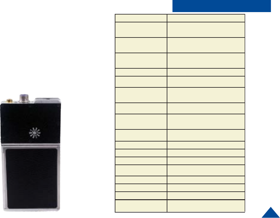
Specifications
Care should be taken when selecting the proper output
power for the T-2350. Higher power will give the greatest
range but will shorten the battery life and increase the
chance of counter detection. DTC recommends using the
lowest possible transmit power that can safely do the job.
The power level must be selected in software. Each
channel can be individually set to either high or low
power.
ITEM SPECIFICATION
Power (RF) 500mW
1000mW
Controls and Indicators • 10 position rotary channel/mode switch
• Sliding ON/OFF power switch
• Bi-color Status LED
Connectors Mic/antenna, combination external
mic/power/programming and
multi-pin connector
Frequency Stability Within +/- 2.5 ppm over -30° C to +65° C
Channel Capacity 10 User programmable with DTC Universal
Software
Frequency Range • 150 - 174 MHz (VHF-High)
• 138 - 150 MHz (Option VHF-Low)
Minimum Tuning Step N/A: Transmitter can be programmed to any channel
within specified frequency band.
Deviation 5 KHz (wide) or TIA/EIA-102 compliant
2.5 KHz (narrow) , programmed by channel
Microphone Electret-fet
Spurious and Harmonics -50 dBc max
Operating Temp Range -30° C to + 70° C
Power Sources Six AAA batteries
Battery Life 5 hours min with AAA batteries measured to half-life
of transmitter output power
Dimensions
Weight
2.275” W x 3.70” L x 0.525” D
Unit .188 lbs / Unit and Batteries .288 lbs
NTIA Compliant TIA/EIA-102 - Analog and Digital mode
NOTE All specifications at 25° C and RF measurements
taken into 50 Ohms unless otherwise stated.
14
Introduction
DTC has improved the flexibility in the programming options you have on the
T-2350 audio transmitter. You can choose to use some, all, or none of this
flexibility.
When you order a T-2350 transmitter, DTC will factory program your frequen-
cies at no additional charge to you. You may want to place a sticker over the
rotary switch on the chassis, so users in the field don’t attempt to change
channels.
DTC will also provide you with free software and a free programming cable,
enabling you to change any programmable option. This is ideal if you often
work with other agencies, or anticipate the equipment being used by a multi-
jurisdictional task force. You can program up to ten channel settings per unit.
In general, this allows you to program at the depot for most variations you
might encounter in the field.
The configuration of each channel is managed with DTC programming
software. The programming software included with your T-2350 allows you
to do all of the following:
Programming
-Assign frequencies to each channel
-Select the mode of operation for each channel
(digital clear, digital encrypted, analog narrow or
analog wideband)
- Select the 56-bit DES-OFB encryption key and
16-bit key ID
-Select power level for each channel (High or Low)
-Select which microphone to use
(mic/antenna or alternate microphone).
TIP: Make sure that you program
your transmitter to match the
frequencies of your receiver, and
test the components as a system
prior to going into the field!
- Select Automatic Gain Control mode
(High Gain AGC, Low Gain AGC, No AGC
(Digital Clear/Encryption Only)
- Select LED operation
(normal operation or disabled)
-Enable/disable recording for each channel
- Turn on/off pre-recorded miniSD™ status and
battery status messages
- Set internal clock
15
Programming
Installing DTC Universal Programming Software
on your PC
NOTE: Uninstall any previous versions by going to Add/Remove Pro-
grams, clicking on DTC Universal Programming, and clicking on
uninstall.
1Click on Start, click on run.
2Click on the Browse button.
3Click on or find your CD drive
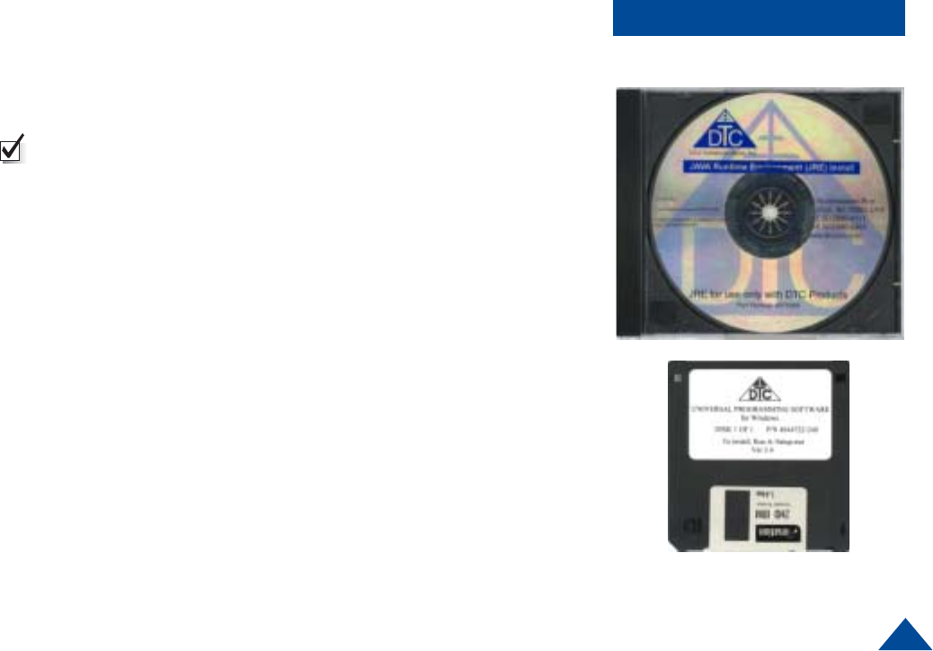
4Install the JAVA Runtime Environment Application first (CD provided).
5Follow the install wizard screens.
6Install the Universal Programming software next (floppy provided).
7Click on Start, click on run.
8Click on the Browse Button.
9Click on your floppy drive.
10 Double click on the setup.
11 Follow the install wizard screens.
Your programming software is installed
16
Programming
Your new settings have been installed.
NOTE: Width refers to channel spacing. 12.5 kHz =
Narrowband. 25 kHz = Wideband
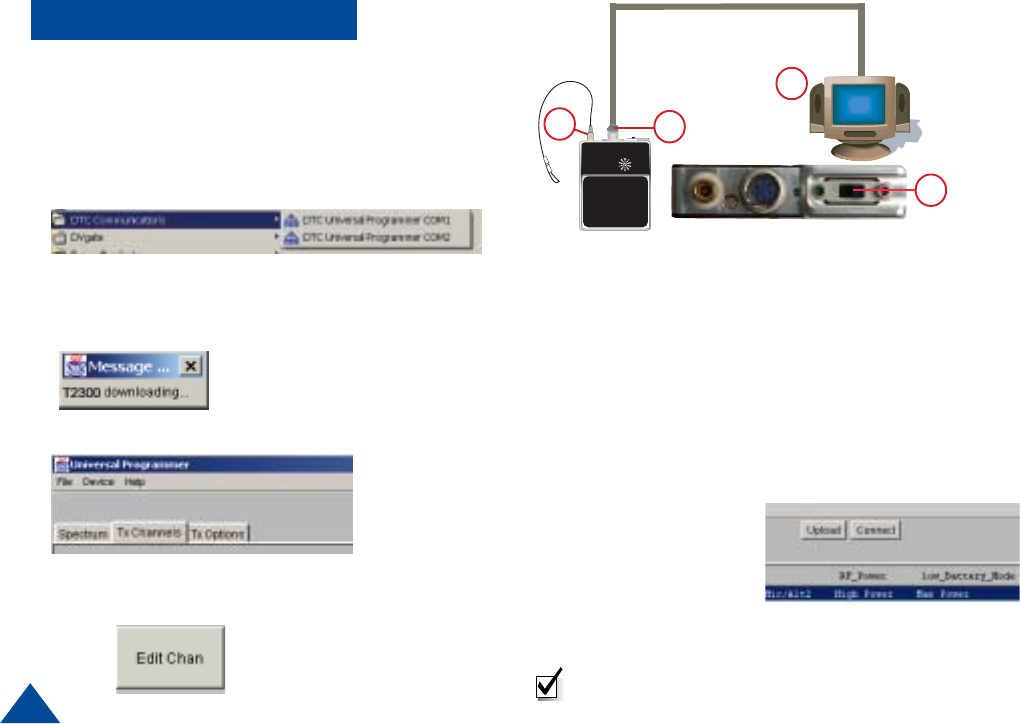
1Connect the antenna to the T-2350 transmitter.
2Install the programming cable into the connector on
the T-2350.
3Plug the serial cable of the programming cable into
the COM1 or COM2 port of your computer.
4From the Start Menu, Select Programs>DTC
Communications>COM1 or COM2 on your computer.
5The cycle power screen displays.
6Slide the power switch to the ON position and click OK.
A message screen displays T-2350 downloading.
7Click on the TX Channels Tab.
6
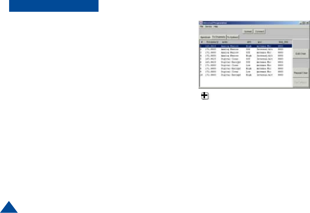
9Enter your new settings and click OK. (See Programming
Options pages 18-21) You can change the frequencies,
mode, key ID, misc source, AGC, and bandwidth
The programming software returns
to the TX channels screen with
your new settings displayed, and
an asterisk (*) beside the channel
that has changed.
10 Click on the upload button.
A message screen displays the new settings being
uploaded to device.
A message screen
displays that your
settings have been
successfully uploaded.
8Click on the channel you need to change and click on
the Edit Channel button
12
3
17
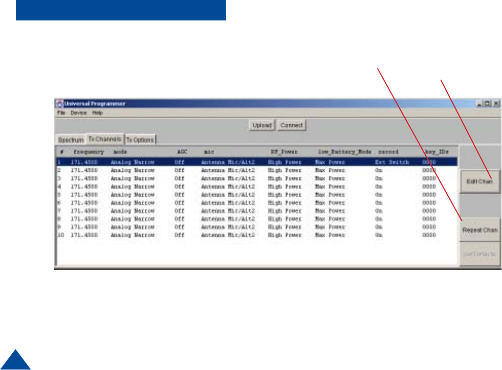
Programming Options
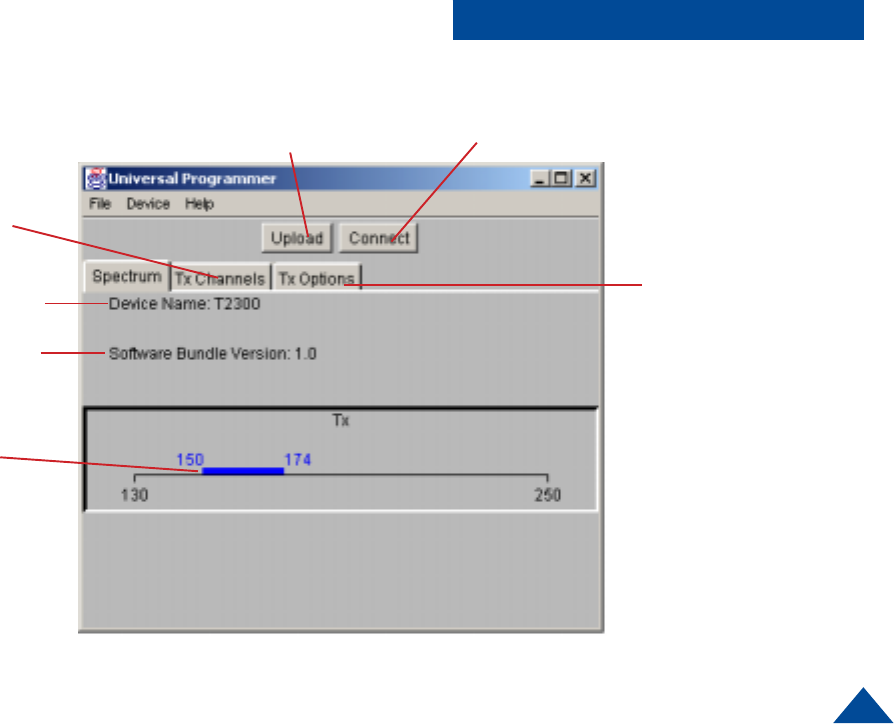
Click this button to establish
communication between unit and PC.
Follow the on-screen instructions.
Uploads new channel information
to the unit. Click this button when all
of the necessary configuration
changes are complete
Global transmit options.
See Page 20
Individual channel
information
See Page 18
Model Number
Firmware Version
Denotes band of
operation
Figure 1
18
Programming Options Click on the channel of
interest, then click this button
to edit individual channel
settings.
Refer to Page 19.
Figure 2
Repeats channel settings
from previously set channel
19
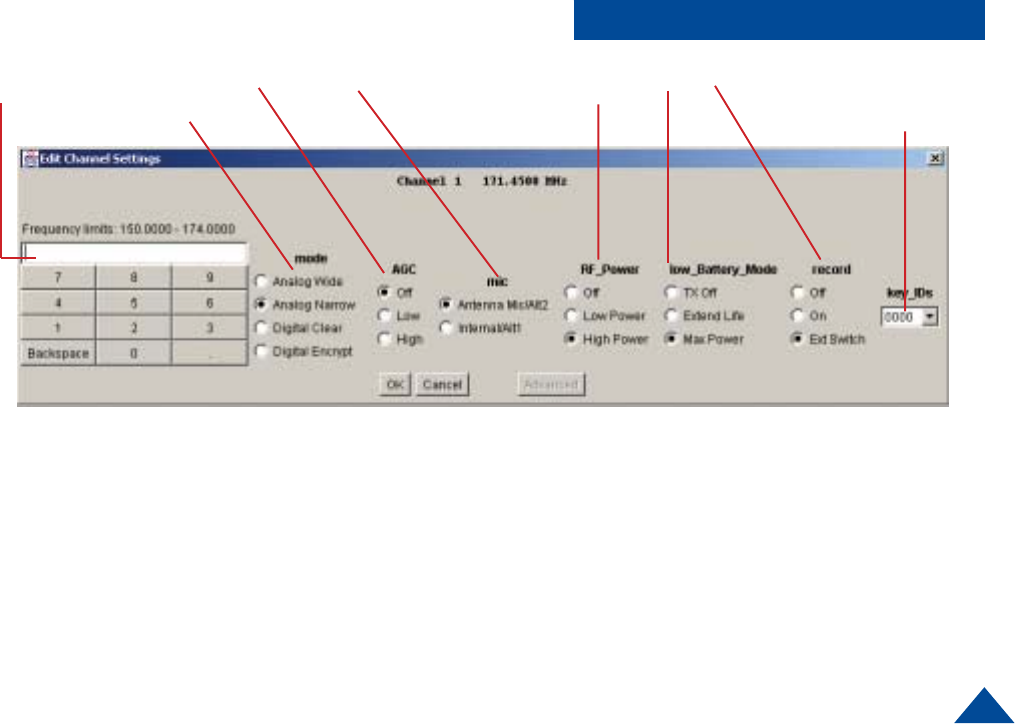
Programming Options
Figure 3
Sets encryption key to be
associated with this channel
C
Select RF Power
Selects Modulations
mode
Enter frequency
in MHz AD
B
A. Selects AGC mode. In analog transmission
modes, AGC Off is not available and will operate as
LOW when selected. In digital transmission mode
all three settings are available.
B. Selects microphone or auxiliary input. When
selecting Internal/ALT1, the internal microphone will
be automatically selected unless there is an external
source connected to ALT1 on the circular connector.
In both settings, an external source will automatically
be selected when connected. When selecting
Antenna Mic/ALT2, you must have either the Antenna
Mic (DTC PN 7011149) or an external input source
connected to ALT2 on the circular connector.
C. Selects RF power operation when unit is in a low battery
condition. When the internal microprocessor detects that the
battery voltage has dropped below 4.1 VDC, the transmit
power will be controlled according to these settings.
Selecting Low Power or Off will prolong battery life, and will
not affect recording settings.
D. Record mode. Disables or enables recording on individual
channels. The Switched setting is intended to be used with
the optional remote recording switch.
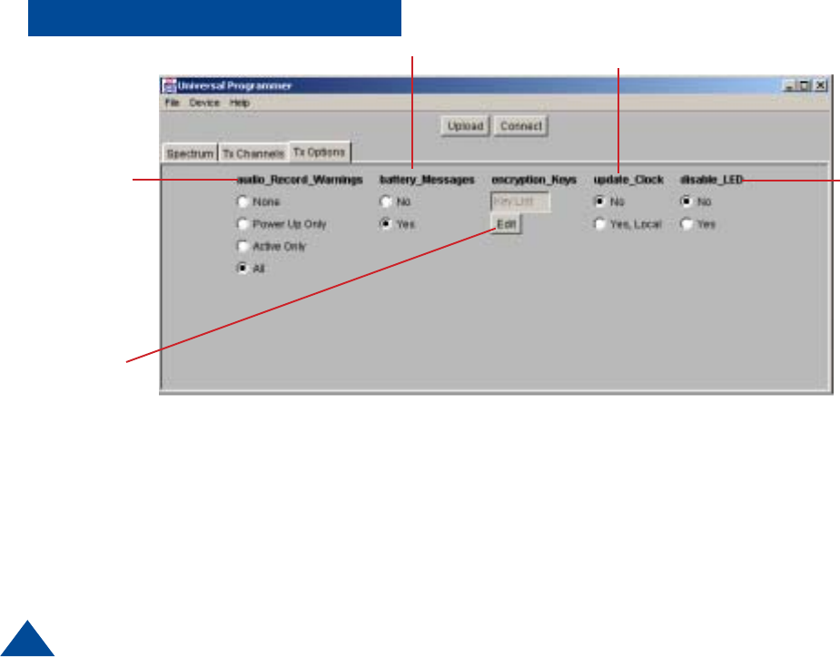
20
E. Turns audio messages On/Off
None - No recording status or warnings will be broadcast.
Power Up - The status of the card will be broadcast on
power up only, not during operation.
Active Only - Record status and warnings will be broad-
cast during operation, but NOT on power up.
All - Record status and warnings will be broadcast during
operation AND on power up.
Figure 4
Turns low battery
Warnings On/Off
Turns external
status
LED On/Off
Edits encryptions
codes and keys.
See Page 21
Programming Options
E
F. Updates clock
Selecting yes will update the T-2350 internal clock using
the time from your computer. The update will be made
when the Upload button is clicked.
F

21
Digital Encryption
In the “Digital Encrypt” mode of opera-
tion, this unit uses a 56-bit DES-OFB
Encryption Key per the APCO Project 25
specification. Each Encryption Key is
identified/labeled using a shorter Key
Identifier (16 bits), known as the KeyID.
If the unit uses the Digital Encrypt mode
of operation, one or more KeyID/key
pairs need to be entered.
0000
0001
0010
0011
0100
0101
0110
0111
1000
1001
1010
1011
1100
1101
1110
1111
(Table 1)
Encryption
Figure A
Hexa
decimal Binary
Encryption
1. To start entering KeyID/Key pairs, select the “Tx Options” tab , and click the Edit
button under “Encryption_Keys”.
2. To enter a new pair, click “Add Item”. In the dialog box (see Figure A), enter a
four-digit hexadecimal number for the KeyID and click “OK”.
3. The KeyID will be displayed at the top of the dialog box, and the program will
then ask to enter the Encryption Key (16 hexadecimal digits). When done
entering the Key, click OK, and the KeyID/Key pair will be entered into the avail-
able list. If the parity of any of the bytes is not odd, the user will be warned
“Wrong parity entered” and the KeyID/Key will have to be re-entered. To protect
the Key, it will not be shown or displayed once it is entered.
Associating a Key/KeyID pair with a
Channel
For each channel with the “Digital
Encrypt” mode selected, a Key/KeyID
pair must be selected. Under the “Tx
Channels” tab, select the channel and
click “Edit Chan”. The Key/KeyID pair
is selected under “key_IDs”. Note that
you only see the KeyID, not the Key
itself. Note that multiple channels
may use the same KeyID/Key pair if
desired. If the mode is not “Digital
Encrypt”, the key_ID setting is ignored
and has no effect.
Entering Key/KeyID pairs
The KeyID is essentially a label for the
DES-OFB Encryption Key. The KeyID is
a 16-bit value, represented by four
hexadecimal digits, with each hexadeci-
mal digit representing 4-bits (see Table
1 below). The Encryption Key is a 64-bit
value (56-bit key + 8 bits parity), repre-
sented by eight hexadecimal digits. Per
the APCO Project 25 specification, each
byte (i.e. pair of hexadecimal digits) in
the Encryption Key must have odd
parity. Odd parity means that the
number of “one’s” in the binary (0/1)
representation of the 8-bit byte must be
odd. For example, the following is a
valid Encryption Key: 2F AB 08 E3 B5
9D 4C 16 . 1
2
3
4
5
6
7
8
9
A
B
C
D
E
F
22
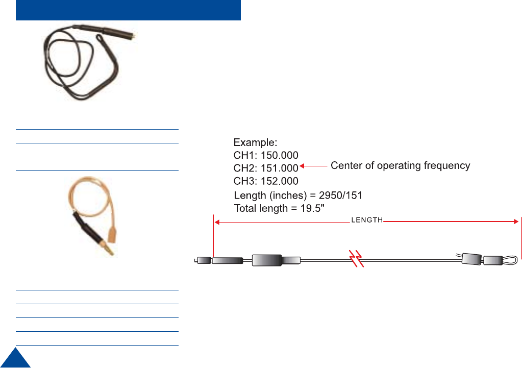
NOODLE ANTENNA
DTC part number
7011151 138 - 225 MHz
(adjustable)
The “noodle” antenna may be adjusted over the frequency range of 138 MHz to 225
MHz by adjusting the amount of wire that is folded back along side the end of the
antenna.
The total length may be calculated by the following formula.
Length (inches) = 2950 / (Freq MHz)
MICROPHONE/ANTENNA
DTC part number Frequency Range
7011149 150 - 174 MHz
7001073 140 - 150 MHz
7001077 210 - 225 MHz
Accessories Antennas

23
DTC Communications, Inc. (DTC) warrants its RF transmitting and receiving products to be free
from defects in workmanship or material for a period of two (2) years from the date of shipment
unless otherwise stated.
The liability of DTC, Inc. under this warranty is limited to replacing, repairing, or issuing credit, at
option, for any products, which are returned by the purchaser during such warranty period, provided:
DTC is notified and a Repair Authorization Number is issued by DTC Customer Service within 30
days after discovery of such defects by Customer.
The defective units are returned to DTC with transportation charged Prepaid by the Customer.
Product damaged in shipment must be reported to and claim forms filed with the Carrier by the
Customer. In shipments to the factory, notice and claim procedures will be initiated by DTC.
DTC’s examination of such products shall disclose to its satisfaction that such defects exist and
have not been caused by misuse, misapplication, neglect, improper installation, improper storage,
alteration, physical damage or accidents.
The warranty shall not apply to microphones, batteries, antennas, crystals or material ordinarily
susceptible to field damage or any accessories of a disposable nature. The warranty shall not apply
to Engineering Prototypes or Customer requested modifications to electronic circuits.
This warranty does not apply to and DTC does not independently warrant items or systems sold by
DTC which are produced by other manufacturers. With respect to such items, the Customer shall
look to the warranty of the original manufacturer and DTC disclaims all warranty, expressed or
implied.
Nothing in this warranty, or any statement, brochure, bulletin, or advertisement is to be interpreted as
establishing the suitability of any product for particular application or use. Applications of the product
and the determination of suitability for any application, is the sole responsibility of the Customer.
TWO YEAR WARRANTY

486 Amherst Street • Nashua, New Hampshire 03063 • 603-880-4411
www.dtccom.com