DTC Communications TAC2001 Survelliance Transmitter for Law Enforcement User Manual TEST PROCEDURE TP1910132 FOR T75 CCA REV A
DTC Communications Inc. Survelliance Transmitter for Law Enforcement TEST PROCEDURE TP1910132 FOR T75 CCA REV A
TAC2001 Manual

DOCUMENT NUMBER: OP1920104 REV. B
DESCRIPTION: TACTICAL REPEATER TAC-COM 2001
OPERATING INSTRUCTIONS
ECO NUMBER:_______
Page____of________
Date:_____________
Orig:_____________
SIGN OFF DATE: mm/dd/yy
Proj Eng._________________
Mfg Mgr. _________________
Documentation ____________
Eng. Mgr._________________
Purchasing _______________
Op1920104 REV B 04/09/01 Page 1of 7
OPERATING INSTRUCTIONS
TAC-COM 2001
TACTICAL REPEATER
OP1920104 REV B
DTC COMMUNICATIONS, INC.
75 Northeastern Blvd.
Nashua, NH 03062
Tel: (603) 880-4411
Fax: (603) 880-6965
Op1920104 REV B 04/09/01 Page 2of 7
Description:
Repeaters are devices, comprised of both a receiver and transmitter, which are used
to extend the range of a transmitter. It does this by receiving a weak signal on one channel
and re-transmitting the signal (at the same time) on a 2nd channel, usually at higher power.
The TAC/COM-2001 is a portable 1.7 Watt VHF FM tactical repeater capable of receiving
both 12.5 kHz (NTIA compliant) and standard wideband (25.0 kHz) signals and re-
broadcasting them as 12.5 kHz signals. The TAC/COM repeater is housed in a sealed,
water resistant, milled aluminum housing and is designed to operate over a wide
temperature and humidity range. Both transmitter and receiver sections are frequency
synthesized; and both are locked to highly stable temperature compensated crystal
oscillators (TCXO’s). The repeater will transmit continuously for over 10 hours on one
battery pack (9 D cells). Special attention has been paid to protecting the switch settings by
the use of a control section door.
Operation:
The typical mission of the repeater is to extend the range of a low power FM
transmitter such as a pager disguise. The repeater should remain in standby (not
transmitting) until the transmitter is activated. When the transmitter is on and in range of
the repeater, the repeater will re-transmit the signal on another selected channel. Typically,
the repeater is powered from its own D-Cell battery box, or via another DC source such as
automotive power. The antenna is very important. The performance of the TAC/COM is
highly dependent on the proper location and orientation of the antenna.
To set up the TAC/COM 2001 repeater, remove the control door by turning the
thumbscrews CCW. First set the bandwidth switch. Is the transmitter that you are using
narrowband (12.5 kHz) or is it an older wideband (25 kHz) unit? It is always best to select
the bandwidth, which matches the transmitter. If unknown, the repeater can receive either
signal in the WB mode, so this is a good default. Note: using a narrowband transmitter with
a wideband receive setting will cause some loss of audio.
The repeater’s receiver channel is next set to the transmitters (bodywire) frequency using
the RX channel control. The repeaters output channel also needs to be set to a channel
covered by the listening post receiver. This is accomplished with the TX channel control.
The squelch control is factory set and normally does not require adjustment.
CAUTION: DO NOT TIGHTEN (TURN CW) THE SQUELCH CONTROL
UNLESS YOU ARE EXPERIENCING A CONSTANT TRANSMIT CONDITION –
Op1920104 REV B 04/09/01 Page 3of 7
TEMPORARILY SWITCH TO ANOTHER CHANNEL; IF THE TRANSMIT
CONDITION STOPS: YOU MAY BE RECEIVING ANOTHER TRANSMISSION
ON THE ORIGINAL CHANNEL.
When the repeater is used in some high noise environments, the squelch may need to be
tightened by turning the squelch control slightly CW until the repeater stops transmitting
(with no input signal). Test the squelch by turning the transmitter on and off a few times.
Remember that adjusting the squelch too far CW (tight) will reduce the range of the
repeater. If you can, try another transmitter channel, which is free of interference.
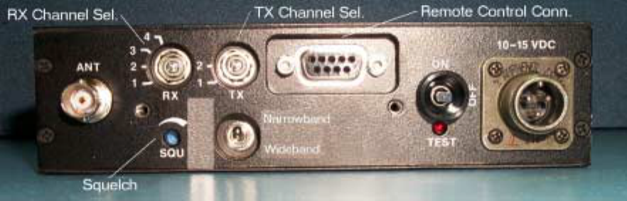
CONTROLS:
1. Channel Switches:
• RX- adjust the slot in the recessed switch labeled RX so that it aligns with the
proper receive channel.
• TX- adjust the slot in the recessed switch labeled TX so that it aligns with the
proper transmit channel.
2. On–Off–Test Switch:
• OFF POSITION- This is a maintained center position switch. In the center position all
power is removed from the Repeater Electronics.
• ON POSITION- This is a maintained position of the switch. To operate the
repeater move the switch to the upper position labeled ON this will apply power
to the repeater electronics.
• TEST- this is a momentary position and is used to verify that power is being
applied to the repeater and that the Transmitter is functional. Momentarily move
the switch to the position labeled test, hold the switch in this position. the TEST
LED should light indicating that power is connected to the repeater. In addition
the transmitter is turned on allowing the user to verify operation of the
transmitter.
3. Power Connector:
• Attach the cigarette plug end of the power cord to the vehicle's power socket
and the other end to the Tactical Repeater's power connector. When using the
optional battery pack a different cable is supplied. This cable connects the
battery pack to the Tactical Repeater.
4. Antenna BNC Connector:
• Connect the supplied antenna to the BNC connector on the TAC-COM 2001
Tactical Repeater. This connection requires a 50-ohm antenna.
Do not turn the repeater on without an antenna attached.
Orient the external “rubber ducky” antenna so that it is in a vertical position. A higher
location like the top story of a building will almost always produce better results than a
below ground level location. Repeater installations near the outer wall or windowed part of
a building will produce better results than inner rooms. If the repeater is to be enclosed in
the trunk of a car, a remotely located, external antenna may be required for best
Op1920104 REV B 04/09/01 Page 4of 7
performance and range. An external antenna will allow the signal to be transmitted more
effectively. Target antenna locations include plastic rear panels and bumpers, or underneath
the vehicle.
Antenna location is the most influential factor in extending range.
5. Squelch Adjustment:
• Make sure the transmitter to be "REPEATED" is not turned on. Turn the
squelch adjustment counterclockwise until the transmitter is turned on (This will
have to be monitored with an additional receiver). Now turn the squelch
adjustment clockwise until the repeater transmitter is just turned off. Once
adjusted, turn the transmitter on and off, while monitoring the repeaters output
frequency. The repeater transmitter should switch on and off, along with the
transmitter being repeated.
6. Bandwidth Switch:
• This switch allows the repeater to selectively RECEIVE either narrowband 12.5
kHz (NTIA compliant) or 25 kHz transmissions. Note that the repeater transmits
strictly in 12.5 kHz bandwidth mode, whatever the input bandwidth.
As with all Wideband/Narrowband switchable devices, if the bandwidth switch is
mistakenly set for 12.5 kHz when a conventional wideband (25 kHz) signal is received,
audio distortion may result on the repeated channel.
Op1920104 REV B 04/09/01 Page 5of 7
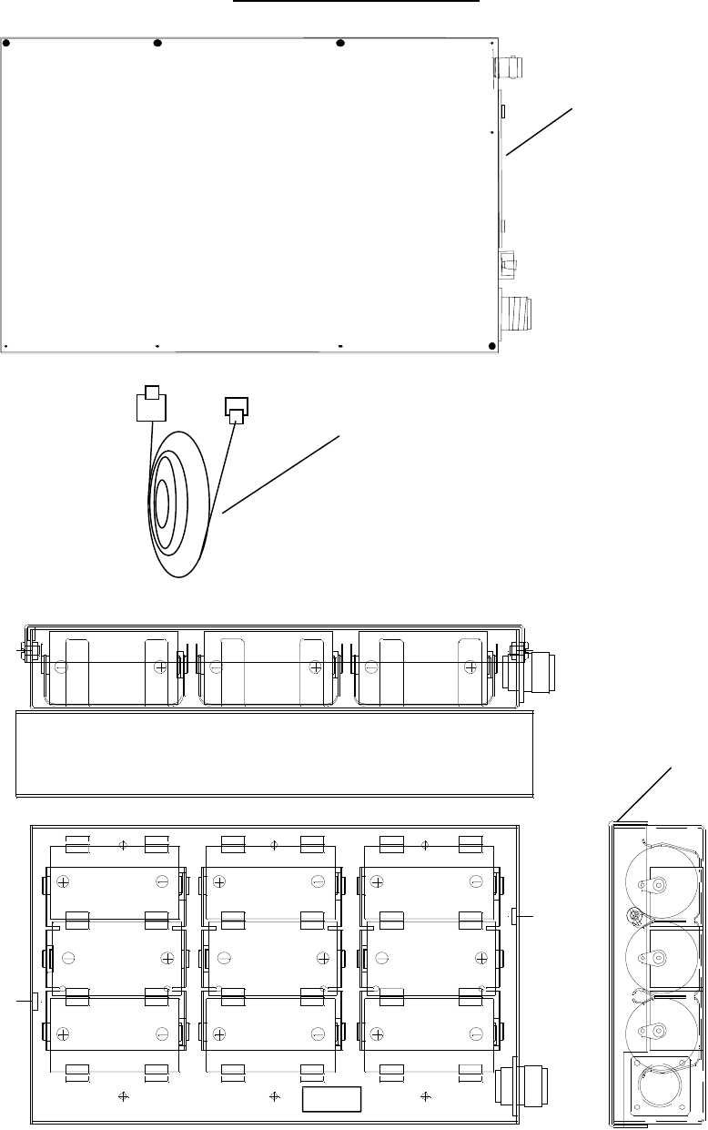
COMPONENTS
Remove cover
To access
Operator controls
Tactical Repeater
Power Cable
Bat Power
Connector
Cover
Mounting to Repeater Using
Optional Mounting Plate
Fuse
Battery Pack

Op1920104 REV B 04/09/01 Page 6of 7
TWO YEAR WARRANTY
DTC Communications, Inc. (DTC) warrants its RF transmitting and receiving products to be free
from defects in workmanship or material for a period of two (2) years from the date of shipment unless
otherwise stated.
The liability of DTC Communications, Inc. under this warranty is limited to replacing, repairing, or
issuing credit at its option, for any products, which are returned by the purchaser during such warranty period,
provided:
DTC is notified and a Repair Authorization Number is issued by DTC Customer Service
within 30 days after discovery of such defects by Customer.
The defective units are returned to DTC with transportation charged Prepaid by the
Customer.
Product damaged in shipment must be reported to and claim forms filed with the Carrier by
the Customer. In shipments to the factory, notice and claim procedures will be initiated by
DTC.
DTC’s examination of such products shall disclose to its satisfaction that such defects
exist and have not been caused by misuse, misapplication, neglect, improper installation,
improper storage, alteration, physical damage or accidents.
The warranty shall not apply to microphones, batteries, antennas, crystals or material
ordinarily susceptible to field damage or any accessories of a disposable nature. The
warranty shall not apply to Engineering Prototypes or Customer requested modifications to
electronic circuits.
This warranty does not apply to and DTC does not independently warrant items or systems
sold by DTC which are produced by other manufacturers. With respect to such items, the
Customer shall look to the warranty of the original manufacturer and DTC disclaims all
warranty, expressed or implied.
Nothing in this warranty, or any statement, brochure, bulletin, or advertisement is to be
interpreted as establishing the suitability of any product for particular application or use.
Applications of the product and the determination of suitability for any application, is the
sole responsibility of the Customer.
75 Northeastern Blvd. Nashua, NH 03062
Op1920104 REV B 04/09/01 Page 7of 7
February, 2001
The information contained in this document is subject to change without
Notice. DTC Communications, Inc. assumes no responsibility for any
errors that may appear in this document.
The text, graphics, and information contained in this document referred
To herein as a manual are furnished as a service of DTC Communications, Inc.
And may not be copied or reproduced except in accordance with terms of
specific agreements with DTC Communications, Inc.
© 2001
DTC Communications, Inc.
75 Northeastern Blvd.
Nashua, New Hampshire 03062
Telephone: (603) 880-4411
Fax: (603) 880-6965
Website: www.dtccom.com