DTC Communications TCCM2005 Tactical Repeater User Manual TacCom2005 Rev4b pmd
DTC Communications Inc. Tactical Repeater TacCom2005 Rev4b pmd
Users Manual Revised
User Programmable
8 Channel RX & TX
Tactical Repeater
NTIA Compliant
DTC COMMUNICATIONS, INCORPORATED
TAC COM 2005

DTC COMMUNICATIONS, INC.
2PN OP1920328 REV 4
copyright notice
Copyright © 2005 - 2006
DTC Communications, Inc. All rights
reserved. No part of this document may be
reproduced, transmitted, transcribed, stored
in a retrieval system or translated into any
language or computer language, in any form
or by any means, including but not limited to
electronic, magnetic, mechanical, optical,
chemical, manual or otherwise, without the
prior written permission of DTC
Communications, Inc.
disclaimer
The information in the document is subject
to change without notice. DTC makes no
representations or warranties with respect to
the contents hereof, and specifically disclaims
any implied warranties of merchantability or
fitness for a particular purpose. DTC reserves
the right to revise this publication and to
make changes from time to time in the
content hereof without obligation of DTC to
notify any person of such revision or changes.
how to contact DTC
For operator and troubleshooting information,
customers are encouraged to refer to the
details in this manual. For additional
clarification or instruction, or to order parts,
contact DTC.
Customer Service is available Monday through
Friday between the hours of 9:00 AM and
5:00 PM EST at:
Tel: 603-880-4411
Fax: 603-880-6965
Website: www.dtccom.com
Email: info@dtccom.com
486 Amherst Street
Nashua, New Hampshire 03063
trademarks
Trademarks of DTC Communications, Inc.
include:
• DTCTM
• PalladiumTM
• ArmorNetTM
• SplitPIXTM
• MiniPIXTM
• DynaViewTM
Other product names used in this manual are
the properties of their respective owners.
FCC information
The following information is provided as a
service to our law enforcement customers who
require a Part 90 station license for video
surveillance operations.
You will need to provide two documents:
• Form 600 (the application form)
• Form 159 (the filing fee form)
Forms can be obtained from the FCC on their
website at:
www.fcc.gov
You can also contact the FCC using their FAX
back service at: (888) 418-3676 Additional
instructions are available by telephone at:
(888) 225-5322
The filing fee form is returned to:
Federal Communications Commission
1270 Fairfield Road
Gettysburg, PA 17325-7245

DTC COMMUNICATIONS, INC. 3
manual conventions
Quick Start .............................................................................. 4
Description .............................................................................. 5
Operation .............................................................................. 7
Components ........................................................................... 8-9
Troubleshooting ................................................................... 10-11
Specifications ............................................................................ 12
Accessories ............................................................................ 13
Warranty ............................................................................ 14
Contact Us ............................................................................ 15
TABLE OF CONTENTS
NOTE: Describes special issues you should
be aware of while using a particular function.
WARNING: Calls out situations in which
equipment could be damaged or a process
could be incorrectly implemented, but in
which operator safety is not a factor.
TIP: Describes application hints.
RF EXPOSURE STATEMENT
A separation distance of at least 20 cm must be
maintained between the antenna and the body of
the user or nearby persons and must not be
co-located or operating in conjunction with any
other antenna or transmitter..
NOTE: This device is for occupational use
only. Occupational users are those persons
who are exposed as a consequence of their
employment, provided these persons are fully
aware of and exercise control over their
exposure.
WARNING: In order to comply with FCC rule
47 CFR 1.1310 regarding general population
radiation exposure, deployment of this device
must be such that unaware bystanders
maintain a minimum separation from the
antenna of 42 cm.
DTC COMMUNICATIONS, INC.
4
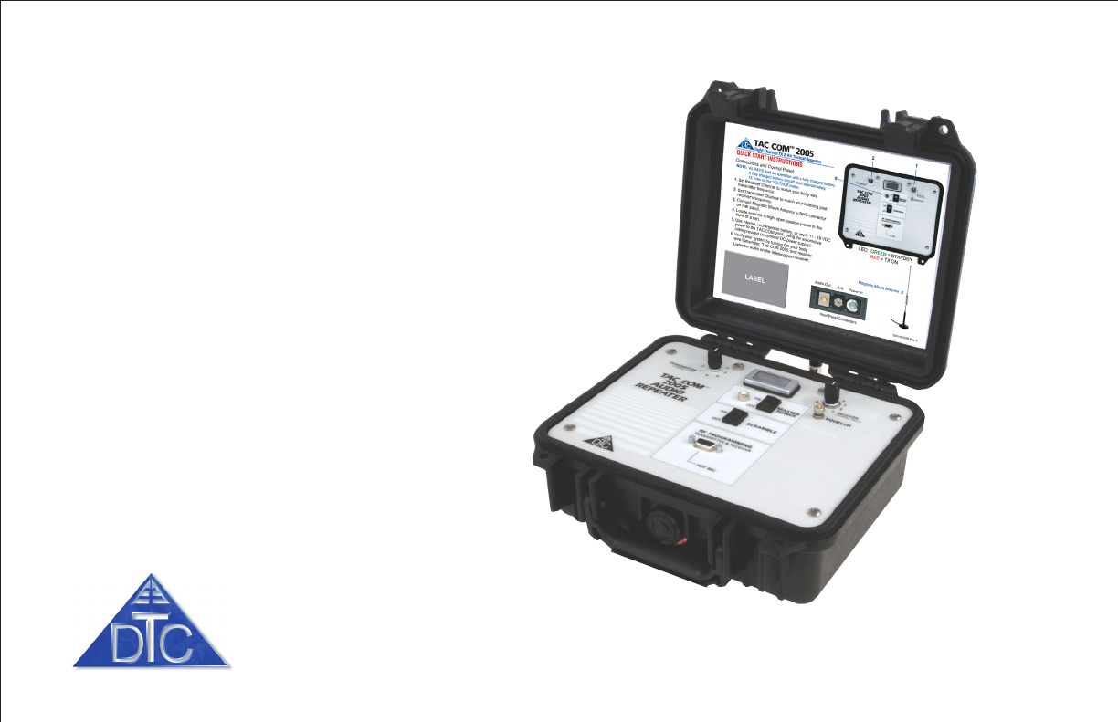
QUICK START
Complete the following steps to
start using your TAC COM 2005:
11
11
1Set Receiver Channel to match
your body wire transmitter
frequency.
22
22
2Set Transmitter Channel to
match your listening post
receiver’s frequency.
33
33
3Connect antenna to BNC
connector on rear panel.
44
44
4Locate antenna in high, open
position (never in the trunk
of a car).
55
55
5Use the internal rechargeable
battery, or apply 11 to 16 VDC
power to the TAC COM 2005
using the automotive power cable
provided (or optional DC supply).
66
66
6Verify system by turning ON your
body wire transmitter,
TAC COM 2005, and receiver.
Listen for audio on the receiver.
LED: GREEN = STANDBY/RECEIVE
RED = TX ON
11
11
1
22
22
2
55
55
5
NOTE: Always fully charge
the internal battery before a
mission.
Audio Out Antenna Power In
66
66
6
Rear Panel Connectors Antenna
33
33
3
DTC COMMUNICATIONS, INC. 5
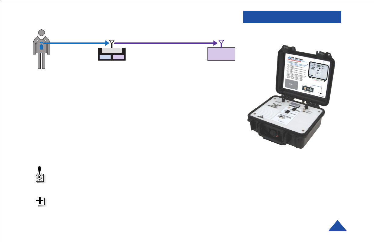
Repeaters are devices comprised of both receiver and transmitter
sections, which are used to extend the range of a transmitted signal.
It does this by receiving a weak signal on one channel and retransmitting
the signal (at the same time) on a second channel, at higher power.
The TAC COM 2005 has special features that extend its capabilities for
surveillance operations. These include a phono output for direct
connection from the repeater to a recorder, an optional HOT MIC for full
time audio signal transmissions, and an optional scrambler to encrypt any
of the TAC COM transmitted signals. In addition to receiver and transmit-
ter options, the TAC COM is capable of connecting with an array of
directional and covert antennas through the use of its standard BNC
antenna connector.
WARNING: Never place the repeater with antenna attached in a
closed trunk of a car. You will degrade your range to the extent that
the repeater is useless.
TIP: DTC recommends the use of highly efficient antennas, such as
the ANT-3 Cellular disguise antenna.
DESCRIPTION
DUPLEXER
TAC COM 2005 BASE STATIO
N
BODY WORN
TRANSMITTER
RX TX
RX
TX

DTC COMMUNICATIONS, INC.
6
DESCRIPTION
The TAC COM 2005 is a portable 2 Watt VHF FM tactical repeater capable
of receiving and transmitting both 12.5 kHz and standard wideband (+25
kHz signals).
Both the receive and transmit frequencies are user-programmable within a
2 MHz range and can be set to any of eight switch selected channels for
both RX and TX. (Programming Kit is optional.) Minimum separation
between receive and transmission frequencies is 3.5 MHz. Programming
cable and software are available as an option. The 2 MHz range and factory
preset frequencies are listed on a label on your TAC COM 2005.
The TAC COM 2005 repeater is housed in a rugged, water resistant,
Pelican case and is designed to operate over a wide temperature and
humidity range. Both transmitter and receiver sections are frequency
synthesized and both are locked to highly stable temperature
compensated crystal oscillators (TCXO’s). The repeater will transmit
continuously for approximately 3 hours on one full charge of the internal
battery.
NOTE: Minimum 3.5 MHz separation between receive and transmit
channels is required. Wider separation between transmit and receive
channels will provide improved performance.

DTC COMMUNICATIONS, INC. 7
NOTE: Do not adjust the
squelch unless you are
experiencing a constant
transmit condition. If that
happens, temporarily switch
to another receive channel.
If the transmit condition
stops, you may be receiving a
third-party transmission on
the original channel.
NOTE: using a wideband
transmitter with a
narrowband receiver setting
will cause some distortion and
loss of some audio.
The typical mission of the repeater is to extend the range of a low power
FM transmitter such as a bodywire. The repeater should remain in
standby mode (not transmitting) until the transmitter is activated. When
the transmitter is keyed ON and in range of the repeater, the repeater will
retransmit the signal on another selected channel. Typically, the repeater
is powered from its own internal rechargeable battery, or via another DC
source such as automotive power. The performance of the TAC COM 2005
is highly dependent on the proper location and
orientation of the antenna.
Is the transmitter that you are using narrowband (12.5 kHz) or is it a
wideband (25 kHz) unit? It is always best to select the bandwidth which
matches the transmitter. If this is unknown, the repeater can receive
either signal in the wideband mode. The TAC COM 2005
bandwidth can be set with the optional software.
The repeater’s receiver channel should be set to the transmitter’s
(bodywire) frequency using the Receiver Channel control. The repeater’s
transmit channel also needs to be set to a frequency covered by the
listening post receiver. This is accomplished with the Transmitter
Channel control. The squelch can be set with the control on the main
panel but it normally should not require adjustment.
If you experience the squelch breaking when the bodywire is off, try
another transmitter channel, which is free of interference. Squelch param-
eters can be modified with the Squelch control.
OPERATION
NOTE: To provide easy
narrowband/wideband
selection capability, program
the same frequency on
different channels using the
wide setting on one and the
narrow setting on the other.
DTC COMMUNICATIONS, INC.
8
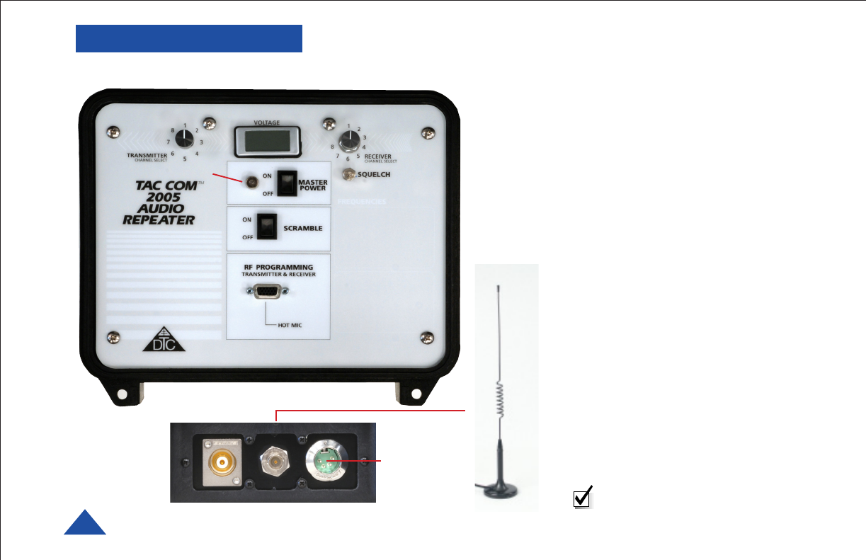
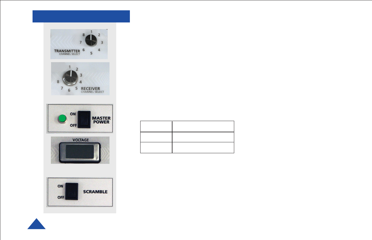
COMPONENTS
Channel Select
TRANSMITTER - This rotary switch selects the channel for the repeater’s
transmitter section. The frequencies are programmed in software.
RECEIVER - This rotary switch selects the channel for the repeater’s
receiver section. The frequencies are programmed in software.
Original factory settings are provided on a label with your equipment
Master Power/ Voltage Meter
MASTER POWER SWITCH - This rocker switch turns ON/OFF the
repeater’s power.
POWER LED - This indicator turns ON when the power is ON. The LED
changes to indicate the following:
VOLTAGE METER - This device measures the voltage present at the
internal battery. 12 Volts is nominal. Low voltage (< 11 VDC) indicates the
battery should be recharged.
Optional Scrambling
SCRAMBLE ON/OFF SWITCH - If your TAC COM 2005 is equipped with
the optional Scrambler feature, a Scramble ON/OFF switch is located on
the main panel. Generally, it is recommended that you test the system
first with the Scramble feature turned OFF. Once the system has tested
successfully, turn the Scramble switch ON. The listening post receiver
must also be equipped with a descrambler.
Green Standby/Receive
Red Transmitter ON
Flickering Weak Signal Receiver
12.6
DTC COMMUNICATIONS, INC. 9
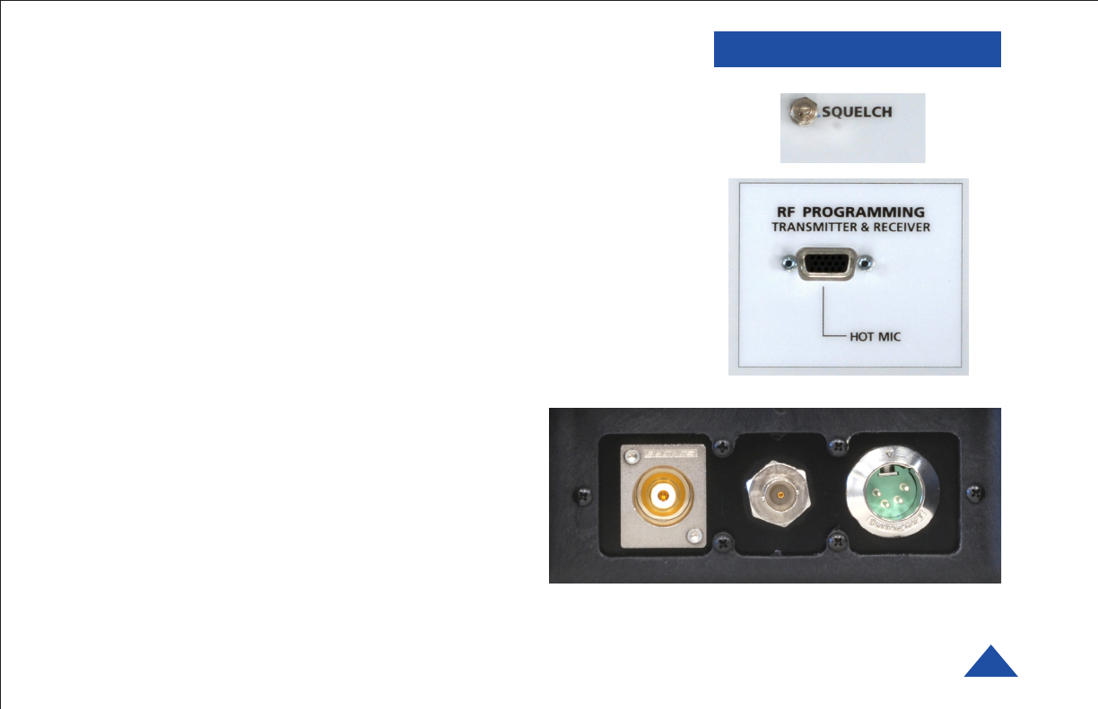
COMPONENTS
Squelch
Adjustment is not usually needed. If needed, make sure the bodywire
transmitter is OFF. Loosen the locknut and use a small screwdriver to turn
the Squelch control on the TAC COM 2005 counterclockwise until the
Master Power LED turns RED. Then turn the adjustment slightly clockwise
until the LED turns GREEN. Finally test the squelch setting by transmit-
ting with the bodywire and observing the listening post receiver, to make
sure it transmits ON/OFF properly. Retighten the locknut.
RF Programming/Hot Mic
TRANSMITTER & RECEIVER/HOT MIC - This DB-15 connector attaches to
an optional serial cable to allow for programming the repeater’s transmitter
and receiver sections. (Programming is optional.) The same connector is
used to connect to the optional Hot Mic.
Antenna Connector
BNC - This RF connector allows for RF transmission.
The device comes with a mag mount antenna, however
optional 50 Ohm external VHF gain antennas can
improve performance.
Line Audio Out
RCA - This audio connector allows for connection
to a recorder or other line-level audio device.
Power/Charging Input
XLR - This connector attaches to the power cable to
allow for automotive auxiliary power. This is also
used with the external AC charger provided. Antenna
Connector
Power/Charger
Input
Audio
Line Out

DTC COMMUNICATIONS, INC.
10
TROUBLESHOOTING
Problem Solution
Unit will not turn ON. Check internal battery voltage as read on the panel meter. If less than 11 VDC, recharge the
battery.
Use an external power source 11 to 16 VDC.
Poor local Audio at Audio out jack. Audio out jack is at line level. It will not drive an external speaker without use of an external
amplifier.
Check battery and antenna on body wire transmitter.
Ensure that body wire transmit frequency and TAC COM 2005 receive frequency are the same.
Ensure that the body wire transmitter is in range of repeater.
Ensure that the TAC COM 2005 antenna is positioned vertically, or an external antenna is in use.
Ensure that an antenna is attached to the antenna jack.
Ensure that the squelch adjust has been performed correctly.
Ensure that the TAC COM 2005 receiver is programmed correctly for wide/narrow bandwidth
operation. This bandwidth must match that of the body-wire transmitter for optimum performance.
Good local audio at the Audio out jack, but
poor or no audio at listening post. Ensure the TAC COM 2005 transmit and listening post receive frequencies are the same.
Ensure that the scramble feature is deactivated.
Check the listening post's receiver program to ensure that any subaudible coding (i.e. PL code)
matches the transmitter, or is turned OFF.
Ensure a clear, line-of-sight path with no buildings or mountains between listening post and
repeater.
Ensure that there is no interference near the listening post. Try changing frequencies.

DTC COMMUNICATIONS, INC. 11
TROUBLESHOOTING
Operating Tips
• Put the TAC COM 2005 on the smart charger until the LED on the
smart charger blinks green and orange, or just green to indicate a
full charge. Charge time is 4 to 6 hours. TAC COM should be OFF
for optimum charging.
NOTE: After extended operation, the battery may be hot (Smart
Charger LED green-red flashing). After battery cool down, the
Smart Charger will automatically revert to fast charge (LED solid
red).
• Ensure the body wire transmit frequency is the same as the
selected TAC COM 2005 receive frequency.
• Choose a frequency that is free of interference.
• Energize the bodywire transmitter and the TAC COM 2005. Using
the Audio Out jack on the rear of the TAC COM 2005, you may
connect an external, amplified speaker or recorder to ensure that
the TAC COM 2005 is receiving the body wire transmitted signal.
• The LED will occasionally begin to flicker between green and red,
sometimes appearing yellow or orange. This is an indication that
the received signal is not strong enough to provide full receiver
quieting. Reposition the ANT-3 Cellular look-alike mobile antenna
with magnetic base to increase signal reception and working
distance.
Operating Tips
• The TAC COM 2005 can be powered with an AC to DC converter,
or an automotive accessory power cord. If the internal battery is
fully charged, it will automatically provide power to your TAC COM
2005. Some automobiles have power-off timers on their accessory
power ports, which could otherwise cause a loss of power if the
automobile timed-off off during operation.
• The TAC COM 2005 will continue to broadcast the received audio
signal on the original transmit frequency even if the transmit
frequency is changed at the front panel. This prevents loss of audio
information during the mission if the channel knob is moved.
To change the channel during transmission:
• Turn OFF the body wire transmitter, or
• Turn OFF the TAC COM 2005, change the
channel, and restore power.
• If using the body-wire with scramble option enabled, DO NOT
activate the TAC COM 2005's scramble feature, as the result will be
a double scrambled signal at the listening post that will not be
readily usable.

DTC COMMUNICATIONS, INC.
12
SPECIFICATIONS General
Weight Approx. 7 Lbs.
Dimensions 10.7 in. x 9.8 in. x 5.0 in.
Operating Temperature Range -10o to +50o C
Power Requirements 12 VDC nominal. Internal rechargeable NiMH
battery and automotive cable. External Input 11
to 16 VDC diode summed with internal battery.
RF
Operating Range 150 to 174 MHz (any pair of 2 MHz TX and RX
bands, separated by 3.5 MHz minimum.
Channels 8 Transmit, 8 Receive
Output Power 2 Watts min.
Programming - Optional
User Programmable TX & RX Software Applications and
Programming Cables Optional Kit
Programming Range 2 MHz bandwidth
Bandwidth Narrow/Wide software selectable
12.5 or 25 KHz
Connectors
Antenna BNC Female 50 Ohms
DC Power 4-pin XLR Male
Programming and Hot Mic High Density DB-15 Female
Audio Line Out RCA Female, line level
Display
Volt Meter 4 to 25 VDC
Charging, Charged External (AC Power Smart Charger)
4 to 6 hours charge time
Optional Features
Scrambling Single Inversion (Optional)
Hot Mic Connection Hot Mic optional
User Programming Optional
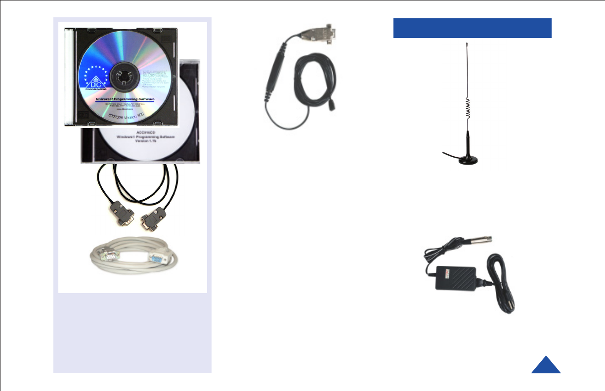
DTC COMMUNICATIONS, INC. 13
ACCESSORIES
The TAC COM 2005 may be turned
into a continuous 2 Watt Transmitter
by attaching the DTC Hot Mic.
When attached via the 15 pin
connector, the Hot Mic disables the
audio receive section. Mic level
audio is connected directly to the
transmit section.
This is ideal when:
A. You are setting up the system and
want to ensure the repeater is within
range of the listening post.
or
B. You require maximum transmit power
using a hard wired microphone, such as
in a vehicle installation.
P/N 4540107
ANT-3 Cellular look-alike
mobile antenna with magnetic
base and BNC connector.
P/N 7011114-T
For Transmitter/Receiver section
channel configuration using a PC.
A free COM port and
DB9 connector is required.
Two software CDs and two cables
are included in kit.
P/N 4045592
TAC COM 2005 Programming Kit
Hot Microphone
Mag-Mount Antenna
Input = 100 to 240 VAC, 47 to 63 Hz
Output = 15 VDC, 2.0 A
P/N 4640137
External AC Power Supply

DTC COMMUNICATIONS, INC.
14
TWO YEAR WARRANTY
DTC Communications, Inc. (DTC) warrants its RF transmitting and receiving products to be free from
defects in workmanship or material for a period of two (2) years from the date of shipment unless
otherwise stated.
The liability of DTC, Inc. under this warranty is limited to replacing, repairing, or issuing credit, at
option, for any products, which are returned by the purchaser during such warranty period, provided:
DTC is notified and a Repair Authorization Number is issued by DTC Customer Service within 30 days
after discovery of such defects by Customer.
The defective units are returned to DTC with transportation charged Prepaid by the Customer.
Product damaged in shipment must be reported to and claim forms filed with the Carrier by the
Customer. In shipments to the factory, notice and claim procedures will be initiated by DTC.
DTC’s examination of such products shall disclose to its satisfaction that such defects exist and have
not been caused by misuse, misapplication, neglect, improper installation, improper storage,
alteration, physical damage or accidents.
The warranty shall not apply to material or accessories ordinarily susceptible to field damage or of a
disposable nature. Examples include batteries, antennas, microphones, headsets, cases,
accessory bags, etc. The warranty shall not apply to Engineering Prototypes or Customer requested
modifications to electronic circuits.
This warranty does not apply to and DTC does not independently warrant items or systems sold by DTC
which are produced by other manufacturers. With respect to such items, the Customer shall look to the
warranty of the original manufacturer and DTC disclaims all warranty, expressed or implied.
Nothing in this warranty, or any statement, brochure, bulletin, or advertisement is to be interpreted as
establishing the suitability of any product for particular application or use. Applications of the product
and the determination of suitability for any application, is the sole responsibility of the Customer.

DTC COMMUNICATIONS, INC. 15
CONTACT US
Contact Information
Nashua Main Office Numbers
486 Amherst Street
Nashua, New Hampshire 03063 USA
(T) 603 880- 4411
(F) 603 880- 6965
Toll Free in the USA
1-800 233 - 8639
REGIONAL SALES MANAGERS
Howard Rich
toll free (888) 819-8570
voice (860) 626-8570
fax (860) 626- 8571
NY, MA, CT, RI, PA, NJ, MD, DE, WV, DC
hrich@dtccom.com
Greg Langley
voice (702) 236- 0021
fax (702) 293-6448
WA, OR, ID, MT, ND, WY, SD
glang46@aol.com
Gary Nichols
toll free (866) 794-2823
voice (765) 473-8917
fax (765) 473-8920
MN, WI, MI, IA, MO, IL, IN, OH, KY, NE
gnichols@dtccom.com
Frank Prioli
toll free (800) 246-2610
voice (727) 392-4761
fax (727) 320-0509
FL, GA, AL, MS, TN, NC, SC, VA
fprioli@dtccom.com
Joe Parkinson
toll free (800) 952- 4914
voice (909) 598-5110
fax (909) 598-3120
CA, AZ, NV, HI, UT, AK, CO, NM
jparkinson@dtccom.com
Christine Guzman
toll free (800) 233-8639
voice (603) 546-2217
fax (603) 880-6965
NH, VT, ME, TX, OK, AR, LA
cguzman@dtccom.com
Inside Sales
State & Local Law Enforcement
603 546-2217
Federal Law Enforcement
603 546-2169
Military
603 546-2121
International
603 546-2217
A complete listing of Contact Individuals
can be located on our website at:
www.dtccom.com

486 Amherst Street • Nashua, New Hampshire 03063 • 603-880- 4411
www.dtccom.com