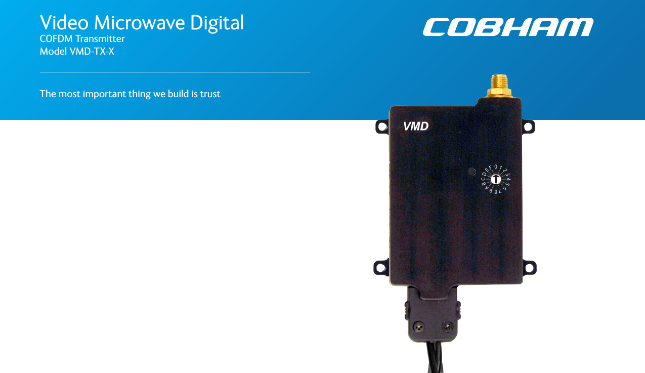
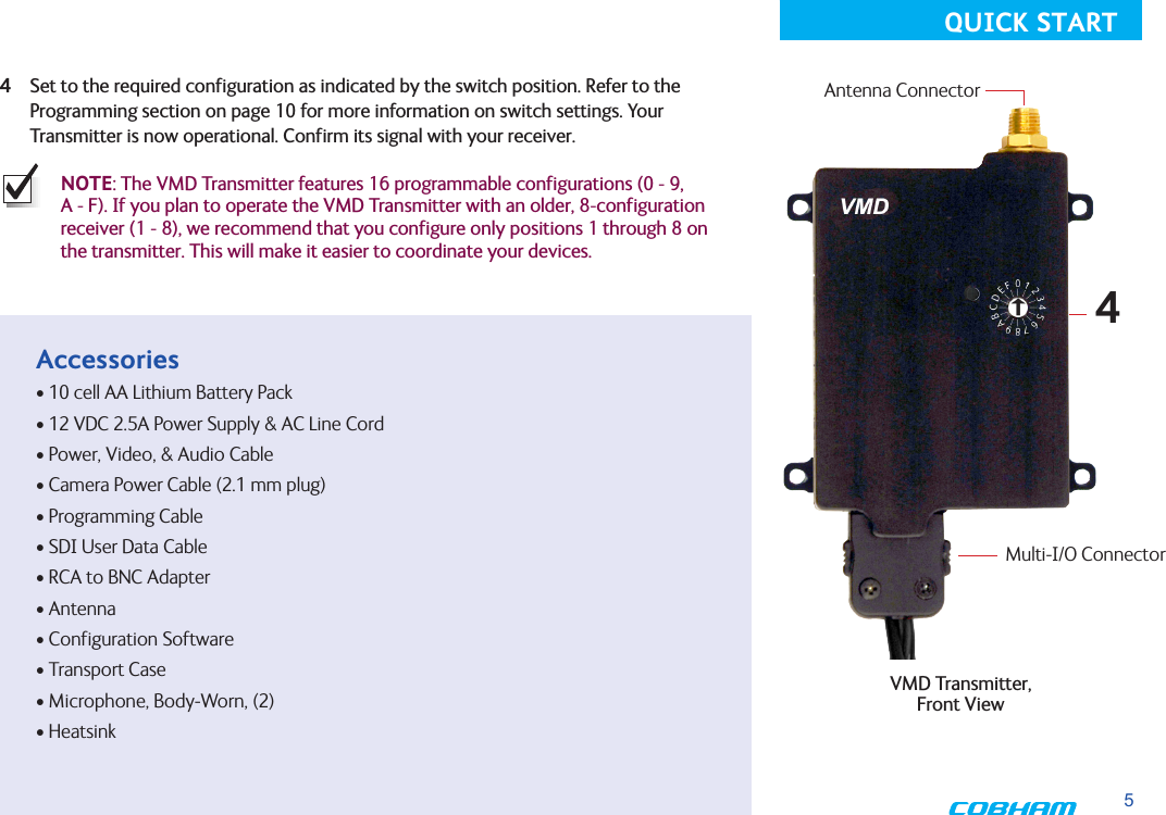
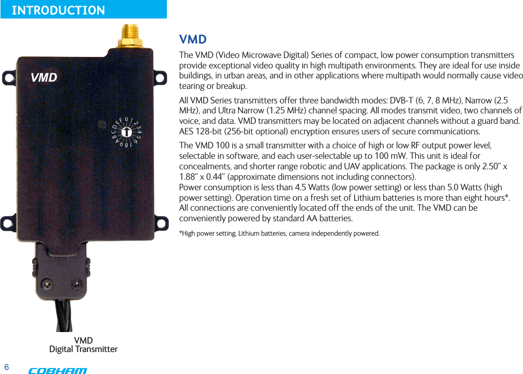
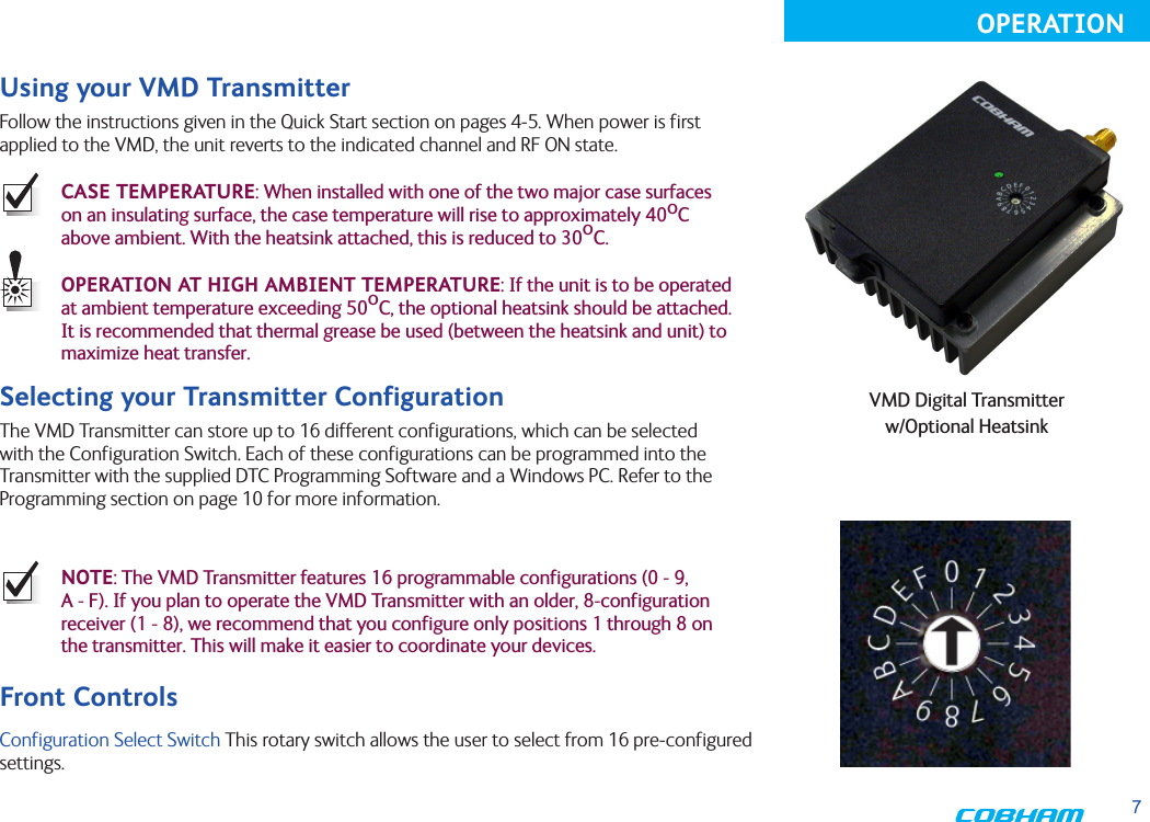
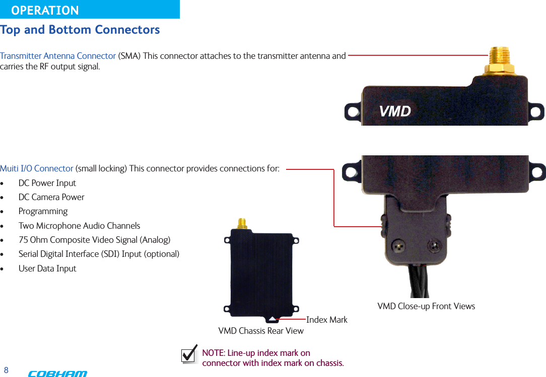
DTC Communications VMDTX100C COFDM Video Transmitter User Manual

DTC Communications Inc. COFDM Video Transmitter

User Manual

Video Microwave Digital COFDM Transmitter Model VMD-TX-XThe most important thing we build is trust
2PN OP1920503 REV. Ecopyright noticeCopyright © 2005 - 2010COBHAM All rights reserved. No part of this document may be reproduced, transmitted, tran-scribed, stored in a retrieval system or translated into any language or computer language, in any form or by any means, including but not limited to electronic, magnetic, mechanical, optical, chemical, manual or otherwise, without the prior written permission of COBHAM. disclaimerThe information in the document is subject to change without notice. COBHAM makes no representations or warranties with respect to the contents hereof, and specifically dis-claims any implied warranties of merchant-ability or fitness for a particular purpose. COBHAM reserves the right to revise this publication and to make changes from time to time in the content hereof without obliga-tion of COBHAM to notify any person of such revision or changes.how to contact COBHAMFor operator and troubleshooting informa-tion, customers are encouraged to refer to the details in this manual. For additional  clarification or instruction, or to order parts, contact COBHAM.Customer Service is available Monday through Friday between the hours of 9:00 AM and  5:00 PM EST at:Tel: 603-880-4411Fax: 603-880-6965Website: www.cobham.com/dtcEmail: dtc.info@cobham.comDTC Communications dba Cobham Surveillance486 Amherst StreetNashua, New Hampshire 03063
3NOTE: Describes special issues you should be aware of while using a particular function.WARNING: Calls out situations in which  equipment could be damaged or a process could be incorrectly implemented, but in which operator safety is not a factor.TIP: Describes application hints.RF EXPOSURE STATEMENTOnly the S-Band unit (DTC Part# VMD-TX-S) unit has been approved for body-worn applications (FCC ID H25VMDTX100S), and only when used in conjunction with DTC’s Palladium Digital VidiVest (DTC Part# Pd-VidiVest-XX) or Digital Video Jacket (Pd-VIDI-DJ). For any configuration other than described above, a separation distance of at least 20 cm must be maintained between the antenna and the body of the user or nearby persons.When units are used consistent with the two previous notices, they comply with FCC radiation exposure limits set forth for an uncontrolled environment , per FCC Rules & Regulations, sections 1.1307, 2.1091 & 2.1093, as required by section 90.1217.NOTE: Do NOT allow the device to directly contact the skin due to warm operating temperatures.manual conventionsQuick Start   ....................................................................................................................4-5Accessories   ........................................................................................................................ 5Introduction   ........................................................................................................................ 6Operation   ....................................................................................................................7-8  Using your VMD Transmitter .............................................................................. 7  Selecting your Transmitter Configuration .................................................... 7  Front Controls ............................................................................................................ 7  Top and Bottom Connectors ............................................................................... 8Programming    .................................................................................................................9-17  System PC Controller Application Software ................................................ 9  Transmitter Control Application .............................................................. 11-17Specifications   .............................................................................................................. 18-19Connector Pin-Out ...............................................................................................................20Notes    ......................................................................................................................21Warranty   ......................................................................................................................22Contact Us   ......................................................................................................................23TABLE OF CONTENTS
41 Connect the transmitter antenna to the SMA connector on the top of the transmitter.2 If you plan to use audio, connect one or two microphones to the Audio 1 (A1) and/or Audio 2 (A2) connectors on the Multi-I/O cable. If using monaural, use Audio 1.3 Connect power and video input via the Multi I/O cable: a Attach your camera video input (75 ohm composite video source in PAL or NTSC) to the Multi I/O cable BNC connector.      b Apply the necessary power to your camera (use supplied cable or external source).   WARNING: There is no reverse polarity protection for the camera power connection. c Attach a 12 VDC power source (such as the supplied battery pack or the AC power adapter) to the Multi I/O cable via the Molex connector. The input voltage range is from 6 to 18 VDC.    d Turn ON your camera.Typical VMD ConfigurationAntennaAudioCameraBattery PackPower OptionA1R/MA2LComplete these steps:123VMD Transmitter, Front View Typical Wiring Configuration for  Analog Video and AudioQUICK START
54 Set to the required configuration as indicated by the switch position. Refer to the Programming section on page 10 for more information on switch settings. Your Transmitter is now operational. Confirm its signal with your receiver.NOTE: The VMD Transmitter features 16 programmable configurations (0 - 9, A - F). If you plan to operate the VMD Transmitter with an older, 8-configuration receiver (1 - 8), we recommend that you configure only positions 1 through 8 on the transmitter. This will make it easier to coordinate your devices.4VMD Transmitter,  Front View Antenna ConnectorAccessories• 10 cell AA Lithium Battery Pack • 12 VDC 2.5A Power Supply & AC Line Cord• Power, Video, & Audio Cable • Camera Power Cable (2.1 mm plug)• Programming Cable• SDI User Data Cable• RCA to BNC Adapter• Antenna• Configuration Software • Transport Case• Microphone, Body-Worn, (2)• HeatsinkMulti-I/O ConnectorQUICK START
6INTRODUCTIONVMDThe VMD (Video Microwave Digital) Series of compact, low power consumption transmitters provide exceptional video quality in high multipath environments. They are ideal for use inside buildings, in urban areas, and in other applications where multipath would normally cause video tearing or breakup. All VMD Series transmitters offer three bandwidth modes: DVB-T (6, 7, 8 MHz), Narrow (2.5 MHz), and Ultra Narrow (1.25 MHz) channel spacing. All modes transmit video, two channels of voice, and data. VMD transmitters may be located on adjacent channels without a guard band. AES 128-bit (256-bit optional) encryption ensures users of secure communications.The VMD 100 is a small transmitter with a choice of high or low RF output power level, selectable in software, and each user-selectable up to 100 mW. This unit is ideal for concealments, and shorter range robotic and UAV applications. The package is only 2.50” x 1.88” x 0.44” (approximate dimensions not including connectors).  Power consumption is less than 4.5 Watts (low power setting) or less than 5.0 Watts (high power setting). Operation time on a fresh set of Lithium batteries is more than eight hours*.  All connections are conveniently located off the ends of the unit. The VMD can be conveniently powered by standard AA batteries. *High power setting, Lithium batteries, camera independently powered.VMD  Digital Transmitter
7OPERATIONUsing your VMD TransmitterFollow the instructions given in the Quick Start section on pages 4-5. When power is first applied to the VMD, the unit reverts to the indicated channel and RF ON state. CASE TEMPERATURE: When installed with one of the two major case surfaces on an insulating surface, the case temperature will rise to approximately 40oC above ambient. With the heatsink attached, this is reduced to 30oC.OPERATION AT HIGH AMBIENT TEMPERATURE: If the unit is to be operated at ambient temperature exceeding 50oC, the optional heatsink should be attached. It is recommended that thermal grease be used (between the heatsink and unit) to maximize heat transfer.Selecting your Transmitter ConfigurationThe VMD Transmitter can store up to 16 different configurations, which can be selected with the Configuration Switch. Each of these configurations can be programmed into the Transmitter with the supplied DTC Programming Software and a Windows PC. Refer to the Programming section on page 10 for more information. NOTE: The VMD Transmitter features 16 programmable configurations (0 - 9, A - F). If you plan to operate the VMD Transmitter with an older, 8-configuration receiver (1 - 8), we recommend that you configure only positions 1 through 8 on the transmitter. This will make it easier to coordinate your devices.VMD Digital Transmitter w/Optional Heatsink   Configuration Select Switch This rotary switch allows the user to select from 16 pre-configured settings.Front Controls
8VMD Chassis Rear ViewNOTE: Line-up index mark on connector with index mark on chassis.OPERATIONTransmitter Antenna Connector (SMA) This connector attaches to the transmitter antenna and carries the RF output signal. Muiti I/O Connector (small locking) This connector provides connections for:•  DC Power Input•  DC Camera Power•  Programming•  Two Microphone Audio Channels•  75 Ohm Composite Video Signal (Analog)•  Serial Digital Interface (SDI) Input (optional)•  User Data InputTop and Bottom ConnectorsVMD Close-up Front ViewsIndex Mark
9Typical VMD ConfigurationAntennaCameraBattery PackPower OptionPROGRAMMINGSystem PC Controller Application SoftwareAdvanced control of the system is available by using the PC control application software. Typically users may want to customize the default configurations to control settings such as frequency, scrambling keys, modulation parameters, and video resolution.The transmitter is controlled by the application DigitalVideoProgrammer.exe located on the CD delivered with the product.A PC is required with an available RS232 Serial COM port to control the transmitter.Installation of the control program is as simple as copying the file from the CD to a suitable location on the PC. No install shield routine is launched. Note that the application generates its own log and initialization files, so it is best to create a dedicated directory for these applications, perhaps with links to the applications from the desktop of the PC.Getting Started•  Use the supplied programming cable to connect the chosen COM port of your PC to the transmitter to be configured.•  Launch the application by double clicking or using the Run... command.NOTE: Please refer to the Digital Video Programmer Application User Guide for information on connecting the VMD to the host computer and the general programming environment.NOTE: The application software overrides the Configuration Select Switch. If the controlling PC is disconnected, the unit will stay at the configuration last commanded until the switch position is changed, at which time the switch resumes control.PROGRAMMING CABLE toPC SERIAL RS-232 PORT10 AA  BATTERY  PACK
10Digital Video Programmer SoftwareThe opening screen of the Application Software, assuming a powered VMD unit is attached to the host computer, looks as shown (right, top).•  The Unit Address is a communication parameter and is read-only.•  To view and change individual configuration settings (as permitted by the Administrator) select the desired number from the scroll table on the upper left.•  The drop-down item Globals sets two  parameters that are common to all 16 configurations (see right, bottom).Heartbeat provides a beating heart icon on the display, useful when viewing a static scene to confirm active input statusSleep Mode powers the unit down, while maintaining RS232 communications.PROGRAMMINGDigital Video Programmer Software Opening ScreenGlobals Drop-down Item
11PROGRAMMINGTransmitter Control Application RF Output  This control is used to turn the RF output on and off. Turn the transmitter RF power on by selecting COFDM.Output Frequency (MHz)The Output Frequency setting allows selection of TX output frequency in increments of 0.25 MHz within the allowed tuning range of the unit. If the unit is set to a frequency that is not an integer multiple of 0.25 MHz, the unit will be automatically set to the closest frequency that is an integer multiple of 0.25MHz. An error message will pop-up warning you that the frequency will not be exactly as specified.RF Bandwidth (MHz)The actual channel bandwidth that the wireless video link will occupy. The DVB-T compliant mode requires a bandwidth setting of 6, 7 or 8 MHz. The narrowband mode bandwidth is either 1.25 or 2.5 MHz. Narrower bandwidths increase receiver sensitivity and extend the maximum distance of the link, however video quality and latency will suffer. Normal default for good quality video is 2.5MHz. The modulation bandwidth may be set to 1.25, 2.5, 6, 7, or 8 MHz.RF Output PowerOutput power selects one of two output power attenuator settings; low power or high power, typically the low power setting is the larger of the two attenuator settings and is used, for instance, if a power amplifier is added to the transmitter and the output power needs to be lowered substantially to prevent overloading the input of the power amplifier.Attenuation - High RF pwr (dB)Output attenuation (dB) is the high power attenuator setting, and is set at the factory for narrowband mask conformance*.Attenuation Low RF pwr (dB)Output attenuation low (dB) is the low power attenuator setting, and is set at the factory for DVB-T mask conformance*.*The value is set at the factory for mask conformance across the full transmitted frequency and ambient temperature ranges (assuming DTC-standard heatsink is attached for ambient temperatures >50 deg.C. This control can be used to make minor adjustments to the output power level, but in normal operation should NOT be changed from factory settings. (0 attenuation = full output power, greater than 0 attenuation = reduced power in 0.25 dB steps.)
12PROGRAMMINGDVBT Provider NameDVB-T provider name is a place to assign a Provider name for the DVB-T configuration. DVBT Service NameDVB-T service name is a place to assign a Service name for the DVB-T configuration. DVBT FEC RateDVB-T FEC rate selects forward error correction rates in the wideband DVB-T modes. Options are 1/2, 2/3, 3/4, 5/6, and 7/8 with 1/2 giving best range and 3/4 possibly giving better video quality under certain conditions. Recommended default is 1/2. DVBT Guard IntervalDVB-T guard interval selects guard intervals in the wideband DVB-T modes or 1/32, 1/16, 1/8, 1/4. Use the smallest guard interval that will allow reliable low error rate communications, this parameter may need to be adjusted when the link is relocated; the recommended default is 1/16.DVBT ModulationDVB-T modulation selects the modulation used in the wideband DVB-T mode. Modulations QPSK, 16QAM, or 64QAM can be selected. QPSK will give best distance and in most cases very good video quality and low latency.DVBT Spectrum InversionDVB-T spectrum inversion allows flipping the modulated spectrum to compensate for spec-trum inversion that may take place on the receiver side due to high side LO injection.DVBT 4 kHz OffsetDVB-T 4 kHz offset is not normally used but might improve BER in cases where the TX upcon-verter I/Q balance is poor.
13PROGRAMMINGNarrowband FECNarrowband FEC sets the forward error correction rate in the narrow bandwidth modes of 1.25 or 2.5 MHz. The two rates available are 1/3 and 2/3; the normal default setting for good quality video is 2/3. Changing the FEC rate to 1/3 will extend the receiver sensitivity by 2 to 3 dB at the expense of degraded video quality and longer latency.Narrowband Guard IntervalNarrowband guard interval is used in the narrowband modes of 1.25 and 2.5MHz to adjust for varying multi-path delay conditions. The default is 1/16 however 1/8 can be selected if necessary to deal with extreme multi-path delays on long links. Selecting 1/8 guard interval could cause a degradation in video quality and latency.Narrowband ModulationNarrowband modulation is used in the narrowband modes to select between QPSK and 16QAM modulation. For best range with good video quality, QPSK is used; 16QAM will give better video quality but will cut down the link range by approximately 50%.Unit NameThe Unit Name is the index for each configuration. It is only transmitted, however, for Narrowband and Ultra-Narrowband modulations. (In DVB-T, Provider Name or Service Name can be used to uniquely identify the device.)
14PROGRAMMING Video InputVideo input selects the video format going into the MPEG video compressor. Options are: OFF (no video input typically used when link is used for data or audio only), PAL, NTSC, NTSC no pedestal, SDI PAL, SDI NTSC.Horizontal ResolutionHorizontal resolution determines the maximum number of horizontal Pixels that can be sampled by the video encoder. For optimal performance this setting should be set to the first value that exceeds the horizontal resolu-tion of the camera in use. Options are: 352, 480, 528, 720 pixels.Video SharpnessVideo sharpness is a filter that may be switched in to smooth out blockiness in the video.MPEG ModeMPEG mode selects the MPEG compression being used, options are: MPEG2 or MPEG-4 (Part 2 ASP). MPEG-4 mode has to be used when in the 1.25 MHz bandwidth mode since this mode can use a nonstandard frame rate that is not supported by MPEG-2. MPEG-4 is not available in DVB-T mode.Video ProfileSelects the chroma format; 4:2:0 or 4:2:2. Note that 4:2:2 is not useful in narrowband modulations due to the degree of compression used.GOP LengthSelects the Group Of Pictures (GOP) size; min. 0, max. 100. Note that system latency increases with GOP length, while reducing the video bit rate. The specified latency of 54 ms for this product applies only for a GOP length of 0. A GOP length of 15 for NTSC video (12 for PAL) will result in a latency of approximately 1/2 a second.Video Bitrate (status only)Video bitrate is a status window that will display the video transport data rate. This varies with bandwidth, modulation, FEC rate and guard interval. The rate will increase with bandwidth and higher levels of modulation, it will go down as the FEC rate and guard interval are increased and other services are active such as data and audio. The video bit rate will also decrease as other service options are activated such as audio and data chan-nels. As a rule video quality and latency improve as the bit rate is increased. MPEG-4 Encoding ModeMPEG4 encoding mode selects the characteristics of the MPEG4 compression. Options are: low delay interlaced, standard delay interlaced, low delay progressive, and standard delay progressive. Interlaced scanning is what is used in conventional over-the-air video. Progressive scan is available on some cameras and involves scanning an entire frame in one pass rather than two in interlaced scanning. MPEG-4 Frame RateMPEG-4 frame rate selects the frame rate used in the MPEG-4 mode, full frame rate is 30 fps for NTSC and 25 fps for PAL a frame rate of 1/2 or less has to be used in 1.25 MHz bandwidth mode. Options are: Full, 1/2, 1/4, 1/8. or 1/24.
15PROGRAMMINGAudio EncoderAudio encoder selects quantity of active audio channels (2 maximum), sampling rate (8, 16 or 32 kHz) which determines upper frequency response, and sampling bits (8 or 12) which determines audio signal to noise.  (Options are listed on right.)NOTE: The higher the sampling rate, the more bandwidth required, which can increase video latency.Audio SourceIf the SDI option has been purchased for the unit, the audio can be sourced from either the microphone inputs (Analog) or embedded audio present in an SDI input stream. Note that if an SDI video input has been selected the microphone input can still be used as the audio source if desired. If Embedded Audio is selected, the Audio Encoder must be set to one of the 48kHz MPEG options.Audio Input LevelAudio input level selects the audio preamp gain level. Options are:  0 dB, 12 dB, 24 dB, 36 dB, 48 dB. Use 24 dB for DTC supplied microphones. Note: 3.5 VDC phantom power is at the microphone input for powering electret condenser microphones.MPEG Layer Audio (kbps)The user can select the MPEG audio bit rate.Higher bit rates result in better audio quality at the receiver. For narrowband modulations, note that selecting higher bit rates will result in restricted data capacity for the video link and will require slow frame rates.MPEG Audio OffsetMPEG Audio Offset is a tool to manually synchronize audio to the video, should it be necessary. The user enters an integer value that offsets the PTS (Presentation Time Stamp) in the MPEG-2 transport stream.Audio DID (SDI data ID)SD-SDI (Standard Definition) can carry up to 16 embedded stereo audio streams, The VMD can extract one of these streams for transmission with video. If SDI embedded audio is selected as the audio source, the hexadecimal DID (Data Identifier) identifies the stream number.Audio Encoder Options are: •  Off •  8 kHz 8 bit mono •  8 kHz 8 bit stereo •  16 kHz 8 bit mono •  16 kHz 8 bit stereo •  32 kHz  8 bit mono •  32 kHz 8 bit stereo •  32 kHz 12 bit mono •  32 kHz 12 bit stereo •  32 kHz MPEG L1 stereo •  32 kHz MPEG L1 mono •  48 kHz MPEG L1 stereo •  48 kHz MPEG L1 mono •  32 kHz MPEG L2 stereo •  32 kHz MPEG L2 mono •  48 kHz MPEG L2 stereo •  48 kHz MPEG L2 mono
16PROGRAMMINGSerial Data (On/Off)Allows activation of the RS232 half-duplex serial data channel and selection of parity (none, even, or odd).Serial Data Baud RateData baud rate selects data channel baud rate, standard rates between 1200 and 115,200 baud are available. Default is 1200. Note that 57600 is not available for DVB-T modes.
17PROGRAMMINGTS IDTransport Stream Identifier.TS Version NumberTransport Stream Version Number.PMT PIDProgram Map Table Packet Identifier.TS Program NumberTransport Stream Program Number.PCR PIDProgram Clock Reference Packet Identifier.Video PIDVideo Packet Identifier.Video Stream IDVideo Stream ID. Audio PID 1Audio Packet IdentifierAudio Stream IDAudio Stream ID. Data PIDData Packet Identifier.EncryptionThis selects from 4 different encryption options; Off (no encryption); ABS, AES128, or  AES 256 (optional).
18PhysicalUnitDimensions(approx.) 2.50”x1.85”x0.44”(notincludingconnectors)64mmx48mmx11mmChassisConnector-RF SMAfemaleEnvironmentalOperationalTemp  -10degreesCto65degreesCOperationalRelativeHumidity upto95%PowerInputVoltage  6.0to18.0VDC(reverse-polarityprotected)PowerConsumption  ~5WforRFOut100mW,~4.5WforRFOut50mW,SleepMode<0.5WOperating Time  8hours+(10NewLithiumAABatteries)ControlPCControlInterface  RS-232Memory  16user-programmablecongurationsVideo EncodingCompressionStandard  MPEG-2(ISO/IEC13818-2),MPEG-4Part2(ASP)DVB-TCompliantLineStandard  NTSC525orPAL625Prole  SP@MLGOPLength  1to100,selectableChromaFormats  4:2:0,4:2:2(DVB-Tonly)VideoBitrates  1Mbpsto10MbpsVideoLatency  Endtoenddelayof54milliseconds(forGOPlength=0)Audio EncodingInput  StereoorDualMonopairEncodingModes:  32kHz/12bit,16kHz/8bit,8kHz/8bit(allStereoorMono)/MPEGLayerI,32kHzor48kHz,  MPEGLayerII,32kHzor48kHzBitrates  64kbpsto448kbpsdependingoncongurationTHD  <0.1%maxResponse  20Hzto15kHz,+/-0.25dBdependingoncongurationCrosstalk  >55dBminS/N  60dBRMSData EncodingAncillarydataformat  FBIstandardancillarydataformatComposite Video InputStandards  NTSCorPALSpecicationRec.  ITU-RBT.470-4,SMPTE170MHorizontalResolution  720,528,480,352pixelsVerticalResolution  480(525lines)or576(625lines)Connector  Multi-I/OCompositePALandNTSCdecoding Eight-bitcomblteringcompositedecoderSDI InputStandards PerSMPTE259MTransmitter Identication (user-dened) DVB-T    ProviderName,ServiceName  Narrow-&Ultra-NarrowBandModulations UnitNameSPECIFICATIONS
19SPECIFICATIONSAnalog Audio2xMicrophoneinputs  compatiblewithTibbets251microphone.ElectretMicbiasprovidedbyphantompower.NominalLevel  +0dBu@1kHzAnalogAudioInputClipLevel +12dBuConnector  JT4MB02(TelocateSystems,BC)EncryptionEncryptiontype  Fixedkeyscramblingsystem.  Algorithmsoffered:ABS(32bitproprietary),AES128,AES256(option)COFDM RF outputRFOutputPower  >20mWinnominal50ΩimpedancewithVSWR<1.5:1Harmonics&Spurious  <-25dBminany1MHzb/wover10MHz–20GHz,outsidespectralmasklimitsRFLoadMismatchTolerance NodamageforinniteVSWR,anyphaseangleforindenitetimeOutputFrequencyBands(options,oneof)   1700–1850MHz,2200–2400MHz,4400–5000MHzFrequencyStepSize  250kHzFrequencyAccuracy  ±10ppmCOFDMStandard  Proprietary1.25or2.5MHzchannelbandwidth,DVB-T.OccupiedBandwidth  1.22/2.44/6/7/8MHzDVB-T modulationAvailableModulations  QPSK,16-QAM,64-QAMFEC  1/2,2/3,3/4,5/6,7/8GuardIntervals  1/32,1/16,1/8,1/4COFDMCarriers  2kPhaseNoiseofDVB-TOFDMcarriers: -65dBc/Hz@1kHzoffset  -75dBc/Hz@10kHzoffset  -86dBc/Hz@100kHzoffset  -105dBc/Hz@1MHzoffsetSpectralMaskofDVB-TOFDMcarriers: b/w MHz dBc  6 7 8 RelLvldBc  3.6 4.2 4.8 -28FreqoffsetfromCntr(MHz)± 6.0 7.0 8.0 -35  8.0 9.3 10.7 -45  12.0 14.0 16.0 -50ModulationErrorRatio  ≥22dBSpectrumInversionCapability YesNarrowband modulationAvailableModulations  QPSK,16-QAMFEC  1/3,2/3GuardIntervals  1/16,1/8COFDMCarriers  400SpectralMaskofOFDMCarriers 2.5MHz(narrowband)25dBc@+/-1.22MHzfromcntr.  1.25MHz(ultranarrowband)25dBc@+/-0.625MHzSpectrumInversioncapability YesDigitalTransportrequirement MPEGTransportStream(ISO/IEC13818-1)TransportStreamParameters(userdened) TS: ID,Vers#&Prog#;  PIDs PCR,PMT,Video,Audio,AncillaryData  IDs VideoStream,AudioStream
20CONNECTOR PIN-OUTHirose connector: Manufacturer’s  Part Number ST40X-18S-CV(80).
21NOTES
             TWO YEAR WARRANTYDTC Communications, Inc. (DTC) warrants its RF transmitting and receiving products to be free from defects in workmanship or mate-rial for a period of two (2) years from the date of shipment unless otherwise stated.The liability of DTC, Inc. under this warranty is limited to replacing, repairing, or issuing credit, at option, for any products, which are returned by the purchaser during such warranty period, provided:DTC is notified and a Repair Authorization Number is issued by DTC Customer Service within 30 days after discovery of such defects by Customer.The defective units are returned to DTC with transportation charged Prepaid by the Customer.Product damaged in shipment must be reported to and claim forms filed with the Carrier by the  Customer.  In shipments to the factory, notice and claim procedures will be initiated by DTC.DTC’s examination of such products shall disclose to its satisfaction that such defects exist and have not been caused by mis-use, misapplication, neglect, improper installation, improper storage, alteration, physical damage or accidents.The warranty shall not apply to material or accessories ordinarily susceptible to field damage or of a disposable nature.  Exam-ples include batteries, antennas, microphones, headsets, cases, accessory bags, etc. The warranty shall not apply to Engineering Prototypes or Customer requested modifications to electronic circuits.This warranty does not apply to and DTC does not independently warrant items or systems sold by DTC which are produced by other manufacturers.  With respect to such items, the Customer shall look to the warranty of the original manufacturer and DTC disclaims all warranty, expressed or implied.Nothing in this warranty, or any statement, brochure, bulletin, or advertisement is to be interpreted as establishing the suit-ability of any product for particular application or use.  Applications of the product and the determination of suitability for any application, is the sole responsibility of the Customer.
23CONTACT USCONTACT USContact InformationNashua Main Office Numbers486 Amherst StreetNashua, New Hampshire 03063 USA(T) 603 880- 4411(F) 603 880- 6965Toll Free in the USA 1- 800 233- 8639REGIONAL SALES MANAGERSHoward Richtoll free (888) 819- 8570voice (860) 626- 8570fax (860) 626-8571NY, MA, CT, RI, PA, NJ, MD, DE, WV, DChrich@cobham.comGary Nicholstoll free (866) 794-2823voice (765) 473-8917fax (765) 473-8920MN, WI, MI, IA, MO, IL, IN, OH, KY, NEgnichols@cobham.comJoe Parkinsontoll free (800) 515-0599voice (928) 443-9399 fax (928) 443-9302CA, AZ, NV, HI, UT, AKjparkinson@cobham.comInside SalesLaw Enforcement1-800 233-8639Military1-800 233-8639OEM1-800 233-8639 A complete listing of Contact Individuals can be located on our website at:www.cobham.com/dtcEd Bryanttoll free (800) 396-0295voice (903) 725-7229fax (903) 725-6952CO, KS, OK, AR, NM, TX, LAebryant@cobham.comPhil Desmond toll free (800) 233-8639  voice (603) 546-2217fax (603) 880-6965NH, VT, ME, WA, OR, ID, MT, ND, WY, SDpdesmond@cobham.comFrank Priolitoll free (800) 246-2610voice (727) 392-4761fax (727) 320-0509FL, GA, AL, MS, TN, NC, SC, VAfprioli@cobham.comFederal Sales Len Corasanitivoice (202) 870-3905fax (410) 544-6538CO, KS, OK, AR, NM, TX, LAlcorasaniti@cobham.com
486 Amherst Street • Nashua, New Hampshire 03063 • 603-880-4411  www.cobham.com/dtcCobham Surveillance

Navigation menu