DTC Communications VMDTX100S PORTABLE VIDEO TRANSMITTER OPERATING IN S-BAND User Manual
DTC Communications Inc. PORTABLE VIDEO TRANSMITTER OPERATING IN S-BAND
Users Manual

PN OP1920503 REV. F
copyright notice
Copyright © 2005 - 2010
COBHAM All rights reserved. No part of this
document may be reproduced, transmitted, tran-
scribed, stored in a retrieval system or translated
into any language or computer language, in any
form or by any means, including but not limited
to electronic, magnetic, mechanical, optical,
chemical, manual or otherwise, without the prior
written permission of COBHAM.
disclaimer
The information in the document is subject
to change without notice. COBHAM makes
no representations or warranties with respect
to the contents hereof, and specifically dis-
claims any implied warranties of merchant-
ability or fitness for a particular purpose.
COBHAM reserves the right to revise this
publication and to make changes from time
to time in the content hereof without obliga-
tion of COBHAM to notify any person of
such revision or changes.
how to contact COBHAM
For operator and troubleshooting informa-
tion, customers are encouraged to refer to
the details in this manual. For additional
clarification or instruction, or to order parts,
contact COBHAM.
Customer Service is available Monday
through Friday between the hours of 9:00
AM and
5:00 PM EST at:
Tel: 603-880-4411
Fax: 603-880-6965
Website: www.cobham.com/dtc
Email: dtc.info@cobham.com
DTC Communications
dba Cobham Surveillance
486 Amherst Street
Nashua, New Hampshire 03063

NOTE: Describes special issues you should be aware of
while using a particular function.
WARNING: Calls out situations in which
equipment could be damaged or a process could be
incorrectly implemented, but in which operator safety is
not a factor.
TIP: Describes application hints.
RF EXPOSURE STATEMENT
FOR BODY-WORN APPLICATIONS, only the S-Band unit, DTC Part#
VMD-TX-S, has been FCC-approved (FCC ID H25VMDTX100S), AND
only when used in conjunction with DTC’s Palladium Digital VidiVest DTC
Part# Pd-VidiVest-S(-RC), or Digital Video Jacket DTC Part# Pd-VIDI-DJ-
S(-RC).
FOR
ANY
CONFIGURATION OTHER THAN THAT DESCRIBED
ABOVE, a separation distance of at least 20 cm MUST be maintained
between the antenna and the body of the user or nearby persons.
When the unit is used consistent with the two previous notices, it
complies with FCC radiation exposure limits set forth for an uncontrolled
environment, per FCC Rules & Regulations, sections 1.1307, 2.1091 &
2.1093, as required by section 90.1217.
NOTE: Do NOT allow the device to directly contact the
skin due to warm operating temperatures.
manual conventions
Quick Start ....................................................................................................................4-5
Accessories ........................................................................................................................ 5
Introduction ........................................................................................................................ 6
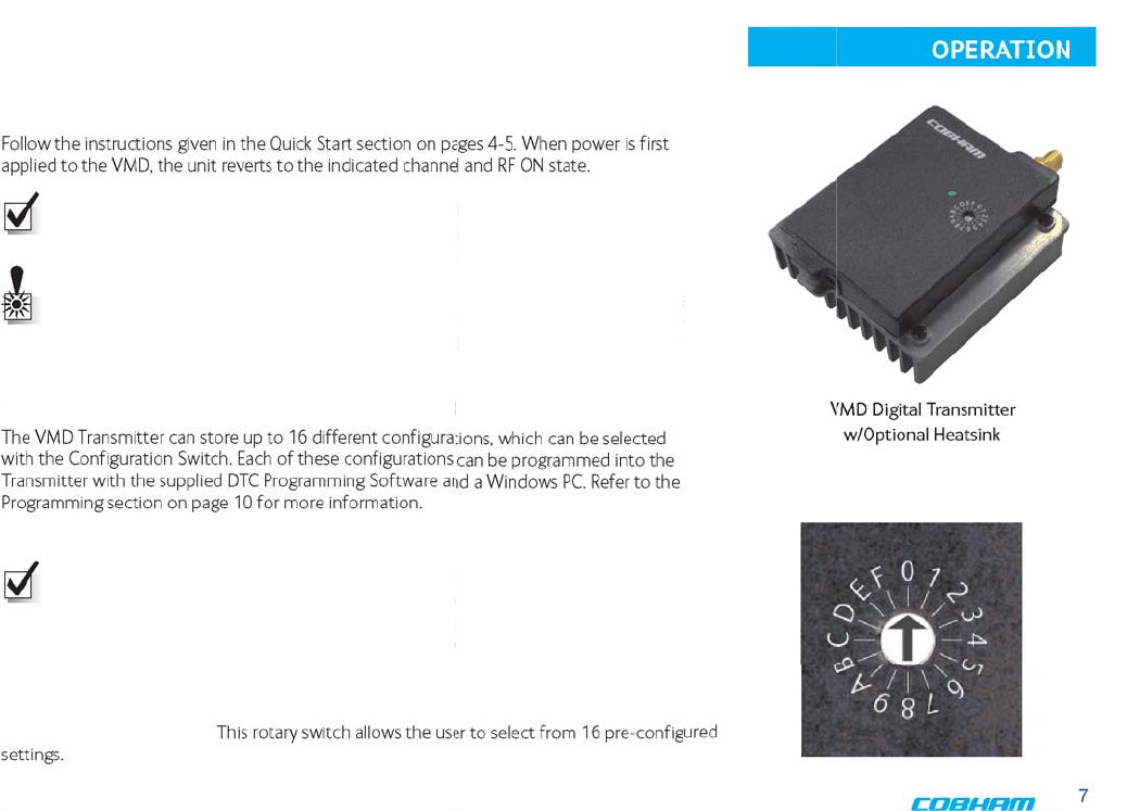
Operation ....................................................................................................................7-8
Using your VMD Transmitter .............................................................................. 7
Selecting your Transmitter Configuration .................................................... 7
Front Controls ............................................................................................................ 7
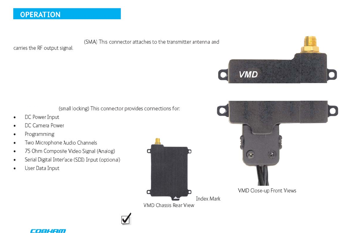
Top and Bottom Connectors ............................................................................... 8
Programming .................................................................................................................9-17
System PC Controller Application Software ................................................ 9
Transmitter Control Application .............................................................. 11-17
Specifications .............................................................................................................. 18-19
Connector Pin-Out ...............................................................................................................20
Notes ......................................................................................................................21
Warranty ......................................................................................................................22
Contact Us ......................................................................................................................23
TABLE OF CONTENTS
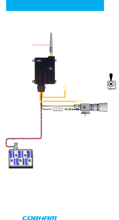
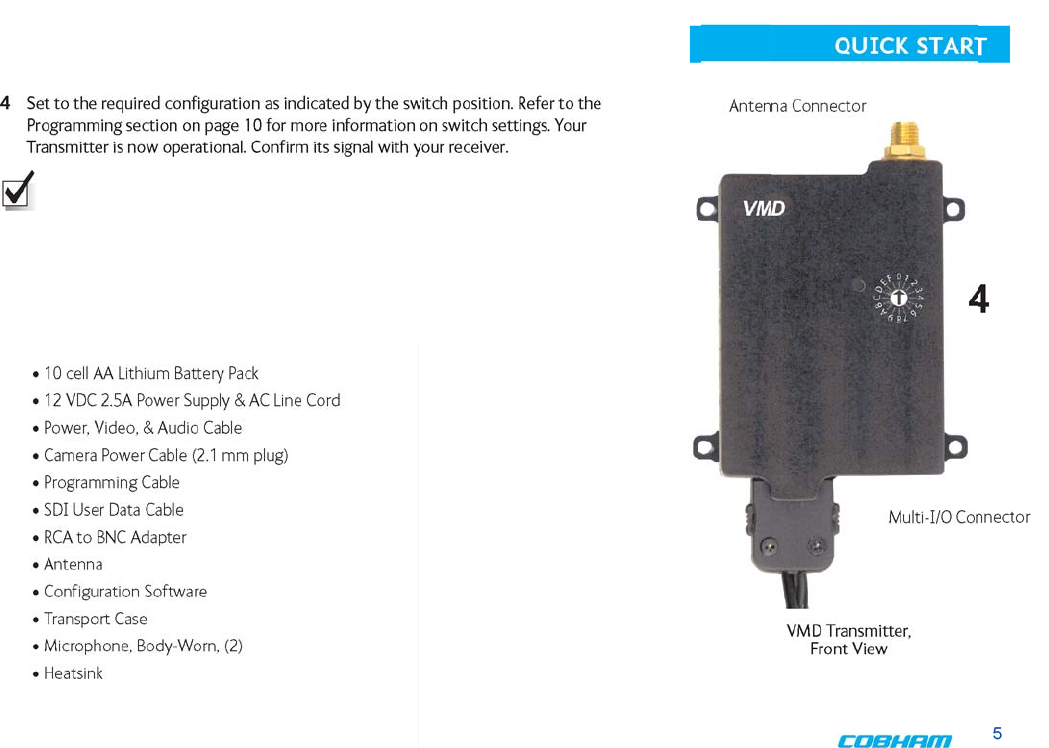
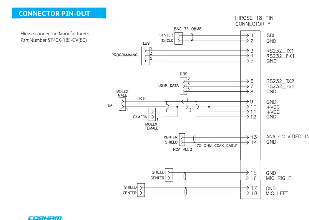
1 Connect the transmitter antenna to the SMA connector on the top of the transmitter.
2 If you plan to use audio, connect one or two microphones to the Audio 1 (A1) and/or
Audio 2 (A2) connectors on the Multi-I/O cable. If using monaural, use Audio 1.
3 Connect power and video input via the Multi I/O cable:
a Attach your camera video input (75 ohm composite video source in PAL or NTSC) to
the Multi I/O cable BNC connector.
b Apply the necessary power to your camera (use supplied cable or external source).
WARNING: There is no reverse polarity protection for the camera power connection.
c Attach a 12 VDC power source (such as the supplied battery pack or the AC power
adapter) to the Multi I/O cable via the Molex connector. The input voltage range is from
6 to 18 VDC.
d Turn ON your camera.
Typical VMD
Configuration
Antenna
Audio
Camera
Battery Pack
Power Option
A1
R/M
A2
L
Complete these steps:
1
2
3
VMD Transmitter, Front View
Typical Wiring Configuration for
Analog Video and Audio
QUICK START
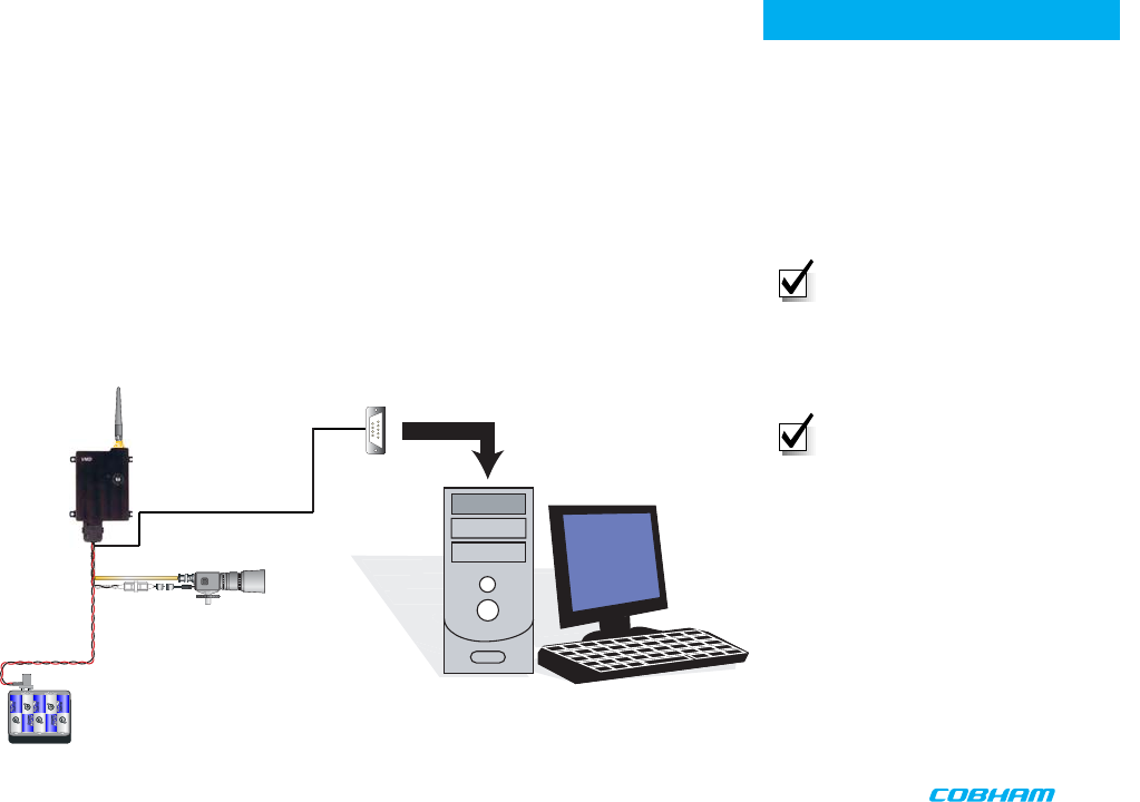
Typical VMD
Configuration
Antenna
Camera
Battery Pack
Power Option
PROGRAMMING
System PC Controller Application Software
Advanced control of the system is available by using the PC control application software.
Typically users may want to customize the default configurations to control settings such as
frequency, scrambling keys, modulation parameters, and video resolution.
The transmitter is controlled by the application 'LJLWDO9LGHR3URJUDPPHUH[H
located on the CD delivered with the product.
A PC is required with an available RS232 Serial COM port to control the transmitter.
Installation of the control program is as simple as copying the file from the CD to a suitable
location on the PC. No install shield routine is launched. Note that the application generates
its own log and initialization files, so it is best to create a dedicated directory for these
applications, perhaps with links to the applications from the desktop of the PC.
Getting Started
• Use the supplied programming cable to
connect the chosen COM port of your
PC to the transmitter to be configured.
• Launch the application by double
clicking or using the 5XQ
command.
NOTE: Please refer to the Digital
Video Programmer Application User
Guide for information on connecting
the VMD to the host computer
and the general programming
environment.
NOTE: The application software
overrides the Configuration Select
Switch. If the controlling PC is
disconnected, the unit will stay at
the configuration last commanded
until the switch position is changed,
at which time the switch resumes
control.
352*5$00,1*&$%/(WR
3&6(5,$/563257
$$
%$77(5<
3$&.
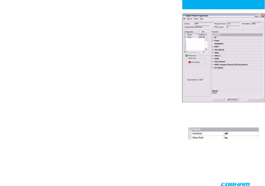
Digital Video Programmer Software
The opening screen of the Application Software, assuming a powered VMD unit is
attached to the host computer, looks as shown (right, top).
• The Unit Address is a communication parameter and is read-only.
• To view and change individual configuration settings (as permitted by the Administrator)
select the desired number from the scroll table on the upper left.
• The drop-down item Globals sets two parameters that are common to all 16
configurations (see right, bottom).
Heartbeat provides a beating heart icon on the display, useful when viewing a static scene
to confirm active input status
Sleep Mode powers the unit down, while maintaining RS232 communications.
PROGRAMMING
Digital Video Programmer Software
Opening Screen
Globals Drop-down Item
PROGRAMMING
Transmitter Control Application
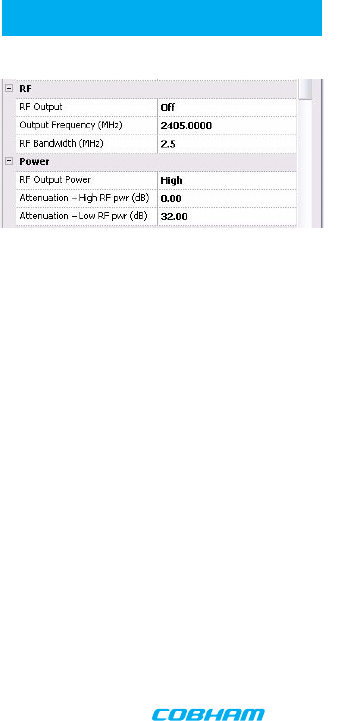
RF Output
This control is used to turn the RF output on and off. Turn the transmitter RF power on by selecting
COFDM.
Output Frequency (MHz)
The Output Frequency setting allows selection of TX output frequency in increments of 0.25 MHz within
the allowed tuning range of the unit. If the unit is set to a frequency that is not an integer multiple
of 0.25 MHz, the unit will be automatically set to the closest frequency that is an integer multiple of
0.25MHz. An error message will pop-up warning you that the frequency will not be exactly as specified.
RF Bandwidth (MHz)
The actual channel bandwidth that the wireless video link will occupy. The DVB-T compliant mode
requires a bandwidth setting of 6, 7 or 8 MHz. The narrowband mode bandwidth is either 1.25 or 2.5
MHz. Narrower bandwidths increase receiver sensitivity and extend the maximum distance of the link,
however video quality and latency will suffer. Normal default for good quality video is 2.5MHz. The
modulation bandwidth may be set to 1.25, 2.5, 6, 7, or 8 MHz.
RF Output Power
Output power selects one of two output power attenuator settings; low power or high power,
typically the low power setting is the larger of the two attenuator settings and is used, for
instance, if a power amplifier is added to the transmitter and the output power needs to be
lowered substantially to prevent overloading the input of the power amplifier.
Attenuation - High RF pwr (dB)
Output attenuation (dB) is the high power attenuator setting, and is set at the factory for
narrowband mask conformance*.
Attenuation Low RF pwr (dB)
Output attenuation low (dB) is the low power attenuator setting, and is set at the factory for
DVB-T mask conformance*.
*The value is set at the factory for mask conformance across the full transmitted frequency and ambient
temperature ranges (assuming DTC-standard heatsink is attached for ambient temperatures >50 deg.C.
This control can be used to make minor adjustments to the output power level, but in normal operation
should NOT be changed from factory settings. (0 attenuation = full output power, greater than 0
attenuation = reduced power in 0.25 dB steps.)
PROGRAMMING
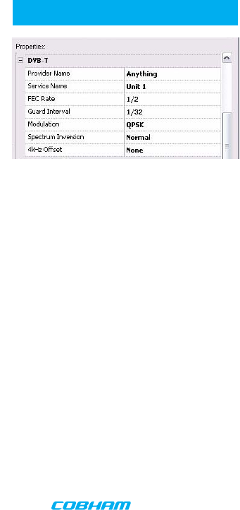
DVBT Provider Name
DVB-T provider name is a place to assign a Provider name for the DVB-T configuration.
DVBT Service Name
DVB-T service name is a place to assign a Service name for the DVB-T configuration.
DVBT FEC Rate
DVB-T FEC rate selects forward error correction rates in the wideband DVB-T modes. Options
are 1/2, 2/3, 3/4, 5/6, and 7/8 with 1/2 giving best range and 3/4 possibly giving better video
quality under certain conditions. Recommended default is 1/2.
DVBT Guard Interval
DVB-T guard interval selects guard intervals in the wideband DVB-T modes or 1/32, 1/16, 1/8,
1/4. Use the smallest guard interval that will allow reliable low error rate communications, this
parameter may need to be adjusted when the link is relocated; the recommended default is
1/16.
DVBT Modulation
DVB-T modulation selects the modulation used in the wideband DVB-T mode. Modulations
QPSK, 16QAM, or 64QAM can be selected. QPSK will give best distance and in most cases
very good video quality and low latency.
DVBT Spectrum Inversion
DVB-T spectrum inversion allows flipping the modulated spectrum to compensate for spec-
trum inversion that may take place on the receiver side due to high side LO injection.
DVBT 4 kHz Offset
DVB-T 4 kHz offset is not normally used but might improve BER in cases where the TX upcon-
verter I/Q balance is poor.
PROGRAMMING
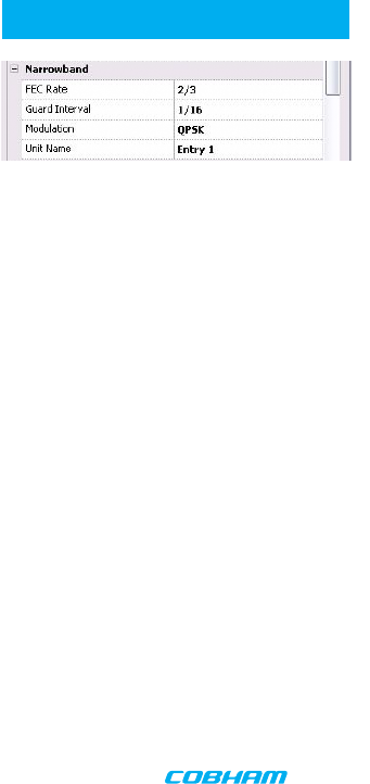
Narrowband FEC
Narrowband FEC sets the forward error correction rate in the narrow bandwidth modes of 1.25 or 2.5
MHz. The two rates available are 1/3 and 2/3; the normal default setting for good quality video is 2/3.
Changing the FEC rate to 1/3 will extend the receiver sensitivity by 2 to 3 dB at the expense of degraded
video quality and longer latency.
Narrowband Guard Interval
Narrowband guard interval is used in the narrowband modes of 1.25 and 2.5MHz to adjust for varying
multi-path delay conditions. The default is 1/16 however 1/8 can be selected if necessary to deal with
extreme multi-path delays on long links. Selecting 1/8 guard interval could cause a degradation in video
quality and latency.
Narrowband Modulation
Narrowband modulation is used in the narrowband modes to select between QPSK and 16QAM
modulation. For best range with good video quality, QPSK is used; 16QAM will give better video quality
but will cut down the link range by approximately 50%.
Unit Name
The Unit Name is the index for each configuration. It is only transmitted, however, for Narrowband and
Ultra-Narrowband modulations. (In DVB-T, Provider Name or Service Name can be used to uniquely
identify the device.)
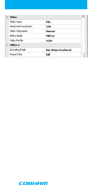
PROGRAMMING Video Input
Video input selects the video format going into the MPEG video compressor. Options are: OFF (no video input
typically used when link is used for data or audio only), PAL, NTSC, NTSC no pedestal, SDI PAL, SDI NTSC.
Horizontal Resolution
Horizontal resolution determines the maximum number of horizontal Pixels that can be sampled by the video
encoder. For optimal performance this setting should be set to the first value that exceeds the horizontal resolu-
tion of the camera in use. Options are: 352, 480, 528, 720 pixels.
Video Sharpness
Video sharpness is a filter that may be switched in to smooth out blockiness in the video.
MPEG Mode
MPEG mode selects the MPEG compression being used, options are: MPEG2 or MPEG-4 (Part 2 ASP). MPEG-4
mode has to be used when in the 1.25 MHz bandwidth mode since this mode can use a nonstandard frame rate
that is not supported by MPEG-2. MPEG-4 is not available in DVB-T mode.
Video Profile
Selects the chroma format; 4:2:0 or 4:2:2. Note that 4:2:2 is not useful in narrowband modulations due to the
degree of compression used.
GOP Length
Selects the Group Of Pictures (GOP) size; min. 0, max. 100. Note that system latency increases with GOP length,
while reducing the video bit rate. The specified latency of 54 ms for this product applies only for a GOP length of
0. A GOP length of 15 for NTSC video (12 for PAL) will result in a latency of approximately 1/2 a second.
Video Bitrate (status only)
Video bitrate is a status window that will display the video transport data rate. This varies with bandwidth,
modulation, FEC rate and guard interval. The rate will increase with bandwidth and higher levels of modulation,
it will go down as the FEC rate and guard interval are increased and other services are active such as data and
audio. The video bit rate will also decrease as other service options are activated such as audio and data chan-
nels. As a rule video quality and latency improve as the bit rate is increased.
MPEG-4 Encoding Mode
MPEG4 encoding mode selects the characteristics of the MPEG4 compression. Options are: low delay interlaced,
standard delay interlaced, low delay progressive, and standard delay progressive. Interlaced scanning is what is
used in conventional over-the-air video. Progressive scan is available on some cameras and involves scanning an
entire frame in one pass rather than two in interlaced scanning.
MPEG-4 Frame Rate
MPEG-4 frame rate selects the frame rate used in the MPEG-4 mode, full frame rate is 30 fps for NTSC and 25
fps for PAL a frame rate of 1/2 or less has to be used in 1.25 MHz bandwidth mode. Options are: Full, 1/2, 1/4,
1/8. or 1/24.
PROGRAMMING
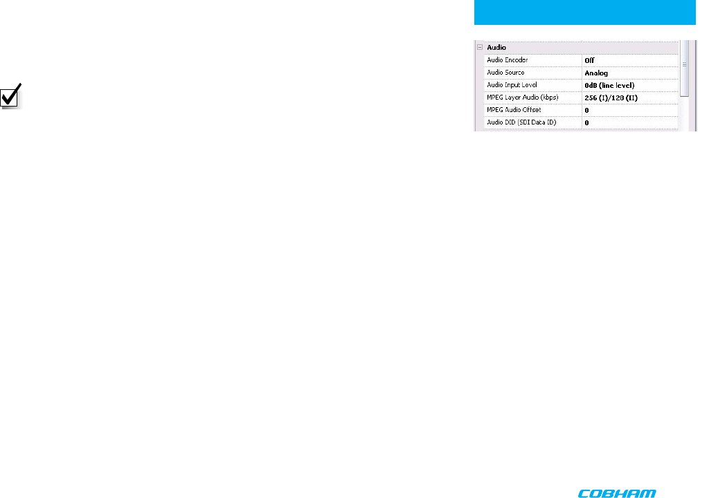
Audio Encoder
Audio encoder selects quantity of active audio channels (2 maximum), sampling rate (8, 16
or 32 kHz) which determines upper frequency response, and sampling bits (8 or 12) which
determines audio signal to noise. (Options are listed on right.)
NOTE: The higher the sampling rate, the more bandwidth required, which can
increase video latency.
Audio Source
If the SDI option has been purchased for the unit, the audio can be sourced from either the
microphone inputs (Analog) or embedded audio present in an SDI input stream. Note that
if an SDI video input has been selected the microphone input can still be used as the audio
source if desired. If Embedded Audio is selected, the Audio Encoder must be set to one of the
48kHz MPEG options.
Audio Input Level
Audio input level selects the audio preamp gain level. Options are:
0 dB, 12 dB, 24 dB, 36 dB, 48 dB. Use 24 dB for DTC supplied microphones. Note: 3.5 VDC
phantom power is at the microphone input for powering electret condenser microphones.
MPEG Layer Audio (kbps)
The user can select the MPEG audio bit rate.
Higher bit rates result in better audio quality at the receiver. For narrowband modulations,
note that selecting higher bit rates will result in restricted data capacity for the video link and
will require slow frame rates.
MPEG Audio Offset
MPEG Audio Offset is a tool to manually synchronize audio to the video, should it be
necessary. The user enters an integer value that offsets the PTS (Presentation Time Stamp) in
the MPEG-2 transport stream.
Audio DID (SDI data ID)
SD-SDI (Standard Definition) can carry up to 16 embedded stereo audio streams, The VMD
can extract one of these streams for transmission with video. If SDI embedded audio is
selected as the audio source, the hexadecimal DID (Data Identifier) identifies the stream
number.
Audio Encoder Options are:
• Off
• 8 kHz 8 bit mono
• 8 kHz 8 bit stereo
• 16 kHz 8 bit mono
• 16 kHz 8 bit stereo
• 32 kHz 8 bit mono
• 32 kHz 8 bit stereo
• 32 kHz 12 bit mono
• 32 kHz 12 bit stereo
• 32 kHz MPEG L1 stereo
• 32 kHz MPEG L1 mono
• 48 kHz MPEG L1 stereo
• 48 kHz MPEG L1 mono
• 32 kHz MPEG L2 stereo
• 32 kHz MPEG L2 mono
• 48 kHz MPEG L2 stereo
• 48 kHz MPEG L2 mono

PROGRAMMING
Serial Data (On/Off)
Allows activation of the RS232 half-duplex serial data channel and selection of parity (none,
even, or odd).
Serial Data Baud Rate
Data baud rate selects data channel baud rate, standard rates between 1200 and 115,200
baud are available. Default is 1200. Note that 57600 is not available for DVB-T modes.
PROGRAMMING
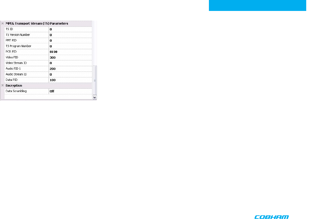
TS ID
Transport Stream Identifier.
TS Version Number
Transport Stream Version Number.
PMT PID
Program Map Table Packet Identifier.
TS Program Number
Transport Stream Program Number.
PCR PID
Program Clock Reference Packet Identifier.
Video PID
Video Packet Identifier.
Video Stream ID
Video Stream ID.
Audio PID 1
Audio Packet Identifier
Audio Stream ID
Audio Stream ID.
Data PID
Data Packet Identifier.
Encryption
This selects from 4 different encryption options; Off (no encryption); ABS, AES128, or
AES 256 (optional).

3K\VLFDO
8QLW'LPHQVLRQVDSSUR[ µ[µ[µQRWLQFOXGLQJFRQQHFWRUVPP[PP[PP
&KDVVLV&RQQHFWRU5) 60$IHPDOH
(QYLURQPHQWDO
2SHUDWLRQDO7HPS GHJUHHV&WRGHJUHHV&
2SHUDWLRQDO5HODWLYH+XPLGLW\ XSWR
3RZHU
,QSXW9ROWDJH WR9'&UHYHUVHSRODULW\SURWHFWHG
3RZHU&RQVXPSWLRQ a:IRU5)2XWP:a:IRU5)2XWP:6OHHS0RGH:
2SHUDWLQJ7LPH KRXUV1HZ/LWKLXP$$%DWWHULHV
&RQWURO
3&&RQWURO,QWHUIDFH 56
0HPRU\ XVHUSURJUDPPDEOHFRQÀJXUDWLRQV
9LGHR(QFRGLQJ
&RPSUHVVLRQ6WDQGDUG 03(*,62,(&03(*3DUW$63'9%7&RPSOLDQW
/LQH6WDQGDUG 176&RU3$/
3URÀOH 63#0/
*23/HQJWK WRVHOHFWDEOH
&KURPD)RUPDWV '9%7RQO\
9LGHR%LWUDWHV 0ESVWR0ESV
9LGHR/DWHQF\ (QGWRHQGGHOD\RIPLOOLVHFRQGVIRU*23OHQJWK
$XGLR(QFRGLQJ
,QSXW 6WHUHRRU'XDO0RQRSDLU
(QFRGLQJ0RGHV N+]ELWN+]ELWN+]ELWDOO6WHUHRRU0RQR03(*/D\HU,N+]RUN+]
03(*/D\HU,,N+]RUN+]
%LWUDWHV NESVWRNESVGHSHQGLQJRQFRQÀJXUDWLRQ
7+' PD[
5HVSRQVH +]WRN+]G%GHSHQGLQJRQFRQÀJXUDWLRQ
&URVVWDON !G%PLQ
61 G%506
'DWD(QFRGLQJ
$QFLOODU\GDWDIRUPDW )%,VWDQGDUGDQFLOODU\GDWDIRUPDW
&RPSRVLWH9LGHR,QSXW
6WDQGDUGV 176&RU3$/
6SHFLÀFDWLRQ5HF ,785%76037(0
+RUL]RQWDO5HVROXWLRQ SL[HOV
9HUWLFDO5HVROXWLRQ OLQHVRUOLQHV
&RQQHFWRU 0XOWL,2
&RPSRVLWH3$/DQG176&GHFRGLQJ (LJKWELWFRPEÀOWHULQJFRPSRVLWHGHFRGHU
6',,QSXW
6WDQGDUGV 3HU6037(0
7UDQVPLWWHU,GHQWLÀFDWLRQXVHUGHÀQHG '9%7 3URYLGHU1DPH6HUYLFH1DPH
1DUURZ8OWUD1DUURZ%DQG0RGXODWLRQV 8QLW1DPH
SPECIFICATIONS

SPECIFICATIONS
$QDORJ$XGLR
[0LFURSKRQHLQSXWV FRPSDWLEOHZLWK7LEEHWVPLFURSKRQH(OHFWUHW0LFELDVSURYLGHGE\SKDQWRPSRZHU
1RPLQDO/HYHO G%X#N+]
$QDORJ$XGLR,QSXW&OLS/HYHO G%X
&RQQHFWRU -70%7HORFDWH6\VWHPV%&
(QFU\SWLRQ
(QFU\SWLRQW\SH )L[HGNH\VFUDPEOLQJV\VWHP
$OJRULWKPVRIIHUHG$%6ELWSURSULHWDU\$(6$(6RSWLRQ
&2)'05)RXWSXW
5)2XWSXW3RZHU !P:LQQRPLQDOїLPSHGDQFHZLWK96:5
+DUPRQLFV6SXULRXV G%PLQDQ\0+]EZRYHU0+]²*+]RXWVLGHVSHFWUDOPDVNOLPLWV
5)/RDG0LVPDWFK7ROHUDQFH 1RGDPDJHIRULQÀQLWH96:5DQ\SKDVHDQJOHIRULQGHÀQLWHWLPH2XWSXW)UHTXHQF\%DQGVRSWLRQVRQHRI
²0+]²0+]²0+]
)UHTXHQF\6WHS6L]H N+]
)UHTXHQF\$FFXUDF\ SSP
&2)'06WDQGDUG 3URSULHWDU\RU0+]FKDQQHOEDQGZLGWK'9%7
2FFXSLHG%DQGZLGWK 0+]
'9%7PRGXODWLRQ
$YDLODEOH0RGXODWLRQV 436.4$04$0
)(&
*XDUG,QWHUYDOV
&2)'0&DUULHUV N
3KDVH1RLVHRI'9%72)'0FDUULHUV G%F+]#N+]RIIVHW
G%F+]#N+]RIIVHW
G%F+]#N+]RIIVHW
G%F+]#0+]RIIVHW
6SHFWUDO0DVNRI'9%72)'0FDUULHUV EZ 0+] G%F
5HO/YOG%F
)UHTRIIVHWIURP&QWU0+]
0RGXODWLRQ(UURU5DWLR G%
6SHFWUXP,QYHUVLRQ&DSDELOLW\ <HV
1DUURZEDQGPRGXODWLRQ
$YDLODEOH0RGXODWLRQV 436.4$0
)(&
*XDUG,QWHUYDOV
&2)'0&DUULHUV
6SHFWUDO0DVNRI2)'0&DUULHUV 0+]QDUURZEDQGG%F#0+]IURPFQWU
0+]XOWUDQDUURZEDQGG%F#0+]
6SHFWUXP,QYHUVLRQFDSDELOLW\ <HV
'LJLWDO7UDQVSRUWUHTXLUHPHQW 03(*7UDQVSRUW6WUHDP,62,(&
7UDQVSRUW6WUHDP3DUDPHWHUVXVHUGHÀQHG 76 ,'9HUV3URJ
3,'V 3&53079LGHR$XGLR$QFLOODU\'DWD
,'V 9LGHR6WUHDP$XGLR6WUHDP

NOTES

TWO YEAR WARRANTY
DTC Communications, Inc. (DTC) warrants its RF transmitting and receiving products to be free from defects in workmanship or mate-
rial for a period of two (2) years from the date of shipment unless otherwise stated.
The liability of DTC, Inc. under this warranty is limited to replacing, repairing, or issuing credit, at option, for any products, which are
returned by the purchaser during such warranty period, provided:
DTC is notified and a Repair Authorization Number is issued by DTC Customer Service within 30 days after discovery of such defects
by Customer.
The defective units are returned to DTC with transportation charged Prepaid by the Customer.
Product damaged in shipment must be reported to and claim forms filed with the Carrier by the
Customer. In shipments to the factory, notice and claim procedures will be initiated by DTC.
DTC’s examination of such products shall disclose to its satisfaction that such defects exist and have not been caused by mis-
use, misapplication, neglect, improper installation, improper storage, alteration, physical damage or accidents.
The warranty shall not apply to material or accessories ordinarily susceptible to field damage or of a disposable nature. Exam-
ples include batteries, antennas, microphones, headsets, cases, accessory bags, etc. The warranty shall not apply to Engineering
Prototypes or Customer requested modifications to electronic circuits.
This warranty does not apply to and DTC does not independently warrant items or systems sold by DTC which are produced
by other manufacturers. With respect to such items, the Customer shall look to the warranty of the original manufacturer and
DTC disclaims all warranty, expressed or implied.
Nothing in this warranty, or any statement, brochure, bulletin, or advertisement is to be interpreted as establishing the suit-
ability of any product for particular application or use. Applications of the product and the determination of suitability for any
application, is the sole responsibility of the Customer.

CONTACT USCONTACT US
Contact Information
Nashua Main Office Numbers
486 Amherst Street
Nashua, New Hampshire 03063 USA
(T) 603 880- 4411
(F) 603 880- 6965
Toll Free in the USA
1- 800 233 - 8639
REGIONAL SALES MANAGERS
Howard Rich
toll free (888) 819-8570
voice (860) 626- 8570
fax (860) 626- 8571
NY, MA, CT, RI, PA, NJ, MD, DE, WV, DC
hrich@cobham.com
Gary Nichols
toll free (866) 794-2823
voice (765) 473-8917
fax (765) 473-8920
MN, WI, MI, IA, MO, IL, IN, OH, KY, NE
gnichols@cobham.com
Joe Parkinson
toll free (800) 515-0599
voice (928) 443-9399
fax (928) 443-9302
CA, AZ, NV, HI, UT, AK
jparkinson@cobham.com
Inside Sales
Law Enforcement
1-800 233-8639
Military
1-800 233-8639
OEM
1-800 233-8639
A complete listing of Contact Individuals can
be located on our website at:
www.cobham.com/dtc
Ed Bryant
toll free (800) 396-0295
voice (903) 725-7229
fax (903) 725-6952
CO, KS, OK, AR, NM, TX, LA
ebryant@cobham.com
Phil Desmond
toll free (800) 233-8639
voice (603) 546-2217
fax (603) 880-6965
NH, VT, ME, WA, OR, ID, MT, ND,
WY, SD
pdesmond@cobham.com
Frank Prioli
toll free (800) 246-2610
voice (727) 392-4761
fax (727) 320-0509
FL, GA, AL, MS, TN, NC, SC, VA
fprioli@cobham.com
Federal Sales
Len Corasaniti
voice (202) 870-3905
fax (410) 544-6538
CO, KS, OK, AR, NM, TX, LA
lcorasaniti@cobham.com
486 Amherst Street • Nashua, New Hampshire 03063 • 603-880-4411 www.cobham.com/dtc
Cobham Surveillance