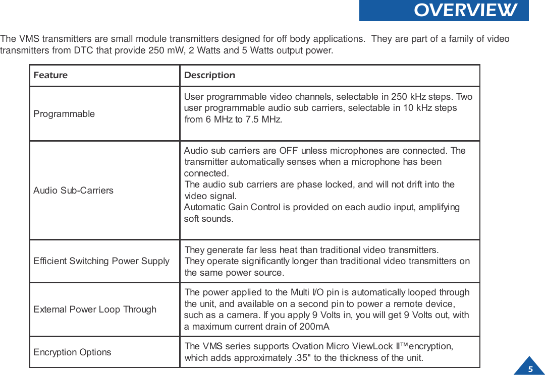
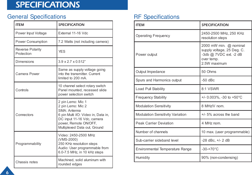
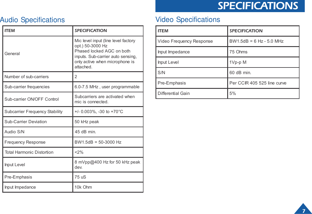
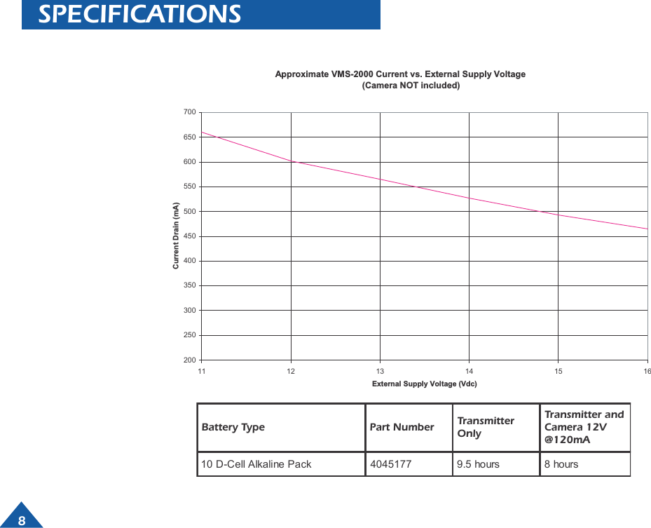
DTC Communications VMS2000 S-Band FM Audio/Video Transmitter User Manual operator manual 2

DTC Communications Inc. S-Band FM Audio/Video Transmitter operator manual 2

Contents

Manual

DTC COMMUNICATIONS INCORPORATED2 W2 W2 W2 W2 WattattattattattVVVVVideo Tideo Tideo Tideo Tideo TransmitterransmitterransmitterransmitterransmitterOperator ManualOperator ManualOperator ManualOperator ManualOperator Manual2 W2 W2 W2 W2 WattattattattattVVVVVideo Tideo Tideo Tideo Tideo TransmitterransmitterransmitterransmitterransmitterOperator ManualOperator ManualOperator ManualOperator ManualOperator ManualVMS-2000 Frequency 2450-2500 MHz           OP1920147 Rev B
How to contact DTCFor operator and troubleshootinginformation, customers are encouraged to refer tothe details in this manual. For additionalclarification or instruction, or to order parts,contact DTC.Customer Service is available Monday throughFriday between the hours of 9:00 AM and5:00 PM EST at:Tel: 603-880-4411Fax: 603-880-6965Website: www.dtccom.comEmail: info@dtccom.com486 Amherst StreetNashua, New Hampshire 03063USACopyright NoticeCopyright © 2003DTC Communications, Inc. All rightsreserved. No part of this document may bereproduced, transmitted, transcribed, stored in a re-trieval system or translated into anylanguage or computer language, in any form or byany means, including but not limited to electronic,magnetic, mechanical, optical, chemical, manual orotherwise, without the prior written permission ofDTC Communications, Inc.DisclaimerThe information in the document is subject to changewithout notice. DTC makes no representations orwarranties with respect to the contents hereof, andspecifically disclaims any implied warranties of mer-chantability or fitness for a particular purpose. DTCreserves the right to revise this publication and tomake changes from time to time in the content hereofwithout obligation of DTC to notify any person of suchrevision or changes.TrademarksTrademarks of DTC Communications, Inc. include:• DTC• MiniPIX®• DynaPIX®Other product names used in this manual are theproperties of their respective owners.WarrantyDTC warrants its manufactured components againstdefects in material and workmanship for a period oftwo (2) years, commencing on the date of originalpurchase.Products manufactured by others that are approvedfor use with DTC equipment are warranted for themanufacturer’s warranty period, commencing fromthe date of shipment from DTC.FCC informationForms can be obtained from the FCC on their web-site at:www.fcc.govYou can also contact the FCC using their FAX backservice at: (888) 418-3676Additional instructions are available by telephone at:(888) 225-5322The filing fee form is returned to:Federal Communications Commission1270 Fairfield RoadGettysburg, PA 17325-72452
3  TABLE OF CONTENTSQuick Start ........................................................................... 4Overview .............................................................................. 5Specification......................................................................... 6Current Drain and Battery Drain .......................................... 8Heatsink Information ............................................................ 9Connectors......................................................................... 10Connections ........................................................................11Equipment Configurations ................................................. 12Optional  Accessories ........................................................ 14Appendix A ......................................................................... 23Programming Introduction.................................................. 24Installing Programming Software ....................................... 25Programming Procedure .................................................... 26Manual ConventionsNOTE Describes special issues you should be aware ofwhile using a particular function.WARNING Calls out situations in which equipment couldbe damaged or a process could be incorrectly imple-mented, but in which operator safety is not a factor.TIP Describes application hints.RF EXPOSURE STATEMENTThis product is NOT to be used in a bodyworn application.Refer to Appendix A in this manual for instruction in theproper use of antennas with this device. When in use aseparation distance of at least 50 cm. must be maintainedbetween the antenna and the body of the user or nearbypersons.Note: This device is for occupational use only. Occupa-tional users are those persons who are exposed as aconsequence of their employment, provided thesepersons are fully aware of and exercise control overtheir exposure.FCC ID# H25VMS2000What should you expect to receive with your 2W Transmitter?1 VMS Video Transmitter1 Dipole antenna with right angle SMA connector1 DTC programming software package1 DTC programming cable1 One Video and Power In “Y” cable
 4QUICK START1Make sure that the power to the transmitter is OFF.2Using a screwdriver, turn the channel selector to the correct channel number.3Connect an antenna to the ANTENNA connector on the module.4Select Hi or Lo Power using the recessed switch.5Connect the microphone or microphones to the MIC-1 and MIC-2 connectorson the module.6Connect a video source and external power (11 -16 VDC) to theVideo/Multi-I/O connector.7Apply power to the transmitterWarning: Do not apply power to the transmitter until an antenna has beenconnected in step 3.Warning: Refer to Appendix A of this manual for information on the properuse of antennas.2NOTE: DTC has provided you with a “Y” cable (power and video) terminatedwith an RCA connector and a BNC adapter for your convenience.NOTE: The dipole antenna included is not recommended for normal use! Thisantenna enables you to quickly set up your transmitter and ensure properoperation.  DTC highly recommends the use of circularly polarized antennasfor the best rejection of multi-path.3546
5OVERVIEWThe VMS transmitters are small module transmitters designed for off body applications.  They are part of a family of videotransmitters from DTC that provide 250 mW, 2 Watts and 5 Watts output power.Feature DescriptionProgrammableUser programmable video channels, selectable in 250 kHz steps. Twouser programmable audio sub carriers, selectable in 10 kHz stepsfrom 6 MHz to 7.5 MHz.Audio Sub-CarriersAudio sub carriers are OFF unless microphones are connected. Thetransmitter automatically senses when a microphone has beenconnected.The audio sub carriers are phase locked, and will not drift into thevideo signal.Automatic Gain Control is provided on each audio input, amplifyingsoft sounds.Efficient Switching Power SupplyThey generate far less heat than traditional video transmitters.They operate significantly longer than traditional video transmitters onthe same power source.External Power Loop ThroughThe power applied to the Multi I/O pin is automatically looped throughthe unit, and available on a second pin to power a remote device,such as a camera. If you apply 9 Volts in, you will get 9 Volts out, witha maximum current drain of 200mAEncryption Options The VMSseries supports Ovation Micro ViewLock II™encryption,which adds approximately .35" to the thickness of the unit.
6 SPECIFICATIONSRF SpecificationsGeneral SpecificationsITEM SPECIFICATIONPower Input Voltage External 11-16 VdcPower Consumption 7.2 Watts (not including camera)Reverse PolarityProtection YE SDimensions 3.9 x 2.7 x 0.512” Camera PowerSame as supply voltage goinginto the transmitter. Currentlimited to 200 mA.Controls10 channel select rotary switchPanel mounted, recessed slidepower selection switch Connectors2 pin Lemo: Mic 12 pin Lemo: Mic 2 SMA: Antenna 6 pin Multi I/O: Video in, Data in,DC input 11-16 Vdc, camerapower, Remote ON/OFF,Multiplexed Data out, GroundProgrammabilityVideo: 2450-2500 MHz(VMS-2000)250 KHz resolution stepsAudio: User programmable from6.0-7.5 MHz, in 10 kHz stepsChassis notes Machined, solid aluminum withrounded edgesITEM SPECIFICATIONOperating Frequency 2450-2500 MHz, 250 KHzresolution stepsPower output2000 mW min.  @ nominalsupply voltage, 25 Deg. C.-3db @ 7VDC ext. -2 dBover temp.2.5W maximumOutput Impedance 50 OhmsSpurs and Harmonics output -50 dBcLoad Pull Stability 8:1 VSWRFrequency Stability +/- 0.003%, -30 to +50°CModulation Sensitivity 8 MHz/V nom.Modulation Sensitivity Variation +/- 5% across the bandPeak Carrier Deviation 4 MHz nom.Number of channels 10 max. (user programmable)Sub-carrier sideband level -28 dBc, +/- 2 dBEnvironmental Temperature Range -30-+70°CHumidity 90% (non-condensing)
7SPECIFICATIONSAudio SpecificationsITEM SPECIFICATIONVideo Frequency Response BW1.5dB = 6 Hz - 5.0 MHzInput Impedance 75 OhmsInput Level 1Vp-p MS/N 60 dB min.Pre-Emphasis Per CCIR 405 525 line curveDifferential Gain 5%Video SpecificationsITEM SPECIFICATIONGeneralMic level input (line level factoryopt.) 50-3000 HzPhased locked AGC on bothinputs. Sub-carrier auto sensing,only active when microphone isattached.Number of sub-carriers 2Sub-carrier frequencies 6.0-7.5 MHz , user programmableSub-carrier ON/OFF Control Subcarriers are activated whenmic is connected.Subcarrier Frequency Stability +/- 0.003%, -30 to +70°CSub-Carrier Deviation 50 kHz peakAudio S/N 45 dB min. Frequency Response BW1.5dB = 50-3000 HzTotal Harmonic Distortion <2%Input Level 8 mVpp@400 Hz for 50 kHz peakdev.Pre-Emphasis 75 uSInput Impedance 10k Ohm
8SPECIFICATIONSBattery Type Part Number TransmitterOnlyTransmitter andCamera 12V@120mA10 D-Cell Alkaline Pack 4045177 9.5 hours 8 hoursApproximate VMS-2000 Current vs. External Supply Voltage(Camera NOT included)20025030035040045050055060065070011 12 13 14 15 16External Supply Voltage (Vdc)Current Drain (mA)
911HEATSINK INFORMATIONBaseplate operating temperature is-20° to + 80°C. Most applications willnot require a heatsink. In applicationswhere the baseplate temperature willexceed +80°, add “-HO” to anyVMXX-2000 transmitter part numberfor the optional heat sink at noadditional charge. The drawing onthe left clearly marks the mountingholes for the heatsink installationwhen required. To install theheatsink.1Align the mounting holes of the transmitter to themounting holes on the heatsink.2Secure the heatsink with four (4) 6-32 x 1”screws.
10MICROPHONE CONNECTORSTwo connectors accommodate two microphone inputs. Eachconnector has two contacts and provides power to themicrophone as well as connecting the audio signal into thetransmitter. The audio sub-carriers are activated by thepresence of the microphone. If a microphone is removed,that sub-carrier is removed from the transmit signal. Turningoff the unused sub-carrier saves power and improves picturequality.Microphone ConnectorsCONNECTORSLemo Male Part # (FFS.01.250.DLAE31)DTC Male Part # (8570003)Hirose Part # HR10A-7P-6P (02)DTC Part # 954020MATING CONNECTORSAntenna ConnectorWARNING: Refer to Appendix A ofthis manual for information on theproper use of antennas.Standard Male SMA ConnectorANTENNASA standard SMA connector is used as the antenna connectoron the VMS-2000. Refer to a list of DTC antennas availableon page 17.TIP: You may use the VMS series transmitters with othermanufacturers antennas. Verify that they are suited forthe band you are operating in.
11CHANNEL SELECT SWITCHSelect a transmission channel by using the rotary switchlocated on the front surface of the transmitter. Use a screw-driver to rotate the switch to the desired channel number.HI/LOW OUTPUT POWER SWITCHSelect Hi or Low power by using the recessed power switch.Switching to Hi poweris equal to 2 Watt output power. Switching to Low power isequal to 1/4 Watt output power.MULTI I/O CONNECTORThe multi I/O (6-pin Multi I/O) connector is mainly used as thevideo and external power input connector. It also providesaccess to many transmitter functions, such as:• Programming the device• Video in• Power in• Remote on• Camera powerCONNECTIONSMulti I/O ConnectorChannel SelectSwitchHI/LO PowerSwitchNOTE: Same as supply voltage. Donot exceed 200 mA.Pin 3: CameraPower OutputPin 1: GroundPin 2: Ext powerinput 11-16VDCPin 6:Video inPin 5:RS-232 in
12BASIC VIDEO TRANSMITTERIt is configured to supply:• The video signal to the transmitterfrom the camera.• Power to the transmitter through amolex connector that can easily beconnected to DTC’s battery packs. Italso comes standard with strippedand tinned leads for a customersuppled power source. A few of theDTC battery packs are listed belowand shown in the illustration:A4045130  (AA Rechargeable)B4045177 ( D-Cell battery pack)AlkalineThe cable does not supply power to the camera. The camerais powered separately with a customer supplied powersource. DTC offers other cables that will supply power to thecamera as an option.TRANSMITTERCAMERAANTENNAPOWER SOURCEfor transmitter only,         9-16 V.CAMERAPOWER+STRIPPED ANDTINNED LEADSSTANDARDABOPTIONALBATTERYPACKSThe basic VMS-2000 configuration consists of the videotransmitter, dipole antenna, and DTC cable part number4045171-024. This cable is connected to the multi I/O port ofthe transmitter.
13 SINGLE  POWER SOURCEIt is configured to supply:• The video signal to the transmitterfrom the camera.• Power to the transmitter through amolex connector that can be easilyconnected to DTC’s battery packs.• Power to the camera through amolex connector that can easily beconnected to DTC’s optionalcameras.NOTE: You will need external camera power if voltage tothe transmitter is not compatible with camera’s operat-ing voltage, and/or you need greater battery life, and/oryour camera draws more than 200 mA.CAMERAANTENNALOOP THROUGH POWERSOURCEFOR TX AND CAMERA11-16 VDCSTRIPPED ANDTINNED LEADSSTANDARDABTRANSMITTERINTERNAL LOOPCAMERA POWEROPTIONALBATTERYPACKSThe VMS-2000 configuration, which uses the loop throughpower source for the  camera, consists of the video transmitter,dipole antenna, and DTC cable part number 405189-024 .This cable is connected to the multi I/O port of the transmitter.
14COMPONENTSPart Number Description4045189-024 Video In/EXT Power/Cam. Power cable, 24”standard.SpecificationsVideo In: Multi I/O to RCA(M) with BNC adaptor(YELLOW)Ext. Power: 24 AWG  wire with a molex connectorand stripped and tinned leads. (RED)Camera Power: 24 AWG wire with a molex  connectorand stripped and tinned leads. (GRAY)Part Number Description4045171-024 Video In/EXT Power/Cam. Powercable, 24”standard.SpecificationsVideo In: Multi I/O to RCA(M) with BNC adaptor(YELLOW)Ext. Power: 24 AWG  wire with a molex connectorand stripped and tinned leads. (RED)Part Number Description4045174-006 Antenna Cable 6” standard4045174-012 Antenna Cable 12” OptionSpecificationsConnectors SMA to TNC
15COMPONENTSPart Number Description7011145-012 Microphone,  12” length7011145-024 Microphone, 24” length7011145-036 Microphone, 36” length7011145-048 Microphone, 48” length7011145-072 Microphone, 6’ length7011145-144 Microphone 12’ length7011145-360 Microphone 30’ lengthPart Number Description4045177 D cell battery pack with locking MolexMicro-fit ConnectorPart Number Description4045173 Programming cable (Connects from the Multi I/O connector to the DB9 connector)This cable plugs into COM1 or COM2, serial ports of a PC. Itallows for the programming of the Video transmitter with theDTC Programming software.
16TO OPEN:TO OPEN: PUSH THIS TAB DOWN TO RELEASE THE MOLEX LOCKING MECHANISM, THEN PULL CONNECTORSAPART.TO CLOSE:PUSH CONNECTORS TOGETHER UNTIL THEMOLEX LOCKING MECHANISM CLICKS AND LOCKSCOMPONENTSPart Number Description4045130 AA (13.5 V) Rechargeable batterypack (NiMH) with Molex Micro-fitConnectorPart Number Description8590138 Terminal, Crimp, Female, micro-fit (3.0)wire size 20-24  AWG plt gold.Molex Part # 43030-00098550104 Receptacle, 2 circuit, micro-fit (3.0)in line. Molex Part # 43645-0200Part Number Description8590139 Terminal, Crimp, Male, Micro-fit (3.0)wire size 20-24 AWG plt. gold.Molex Part # 43031-00098550101 Plug, 2 circuit, Micro-fit (3.0)In line. Molex Part # 43640-0200Part Number DescriptionANT-VIL Dipole Antenna 1.70-1.85 GHz withright angle SMA adaptorANT-VIS Dipole Antenna 2.4-2.5 GHz withright angle SMA adaptorThe ANT-VIL/S is a 1/2 wave coaxial dipole portable duckantenna. It can be mounted directly to the video  transmitter, orat a right angle using  the adaptor provided.
17ANTENNASANT-2WARNING: Refer to Appendix A of this manual for information on the properuse of antennas.Part Number Description7011129 ANT-2 2dB: Dipole 1.7-1.85 GHzMust be used with SMA to TNC antenna cable (4045174-006).7011131 ANT-2 2dB: Dipole 2.4-2.5 GHzMust be used with SMA to TNC antenna cable (4045174-006).ANT-2 is a rugged, lightweight linearly  polarized dipole for use in the 2.4 to 2.5GHz and 1.7-1.85 GHz bands. It can be mounted at the end of a cable with acompatible connector. This antenna is ground plane independent.SpecificationsType Sleeve DipolePolarization LinearPeak Gain 2 dBiHorizontal Beamwidth OmnidirectionalVertical Beamwidth 77°Nominal Impedance 50 OhmsGroundplane Req. Not requiredSize 4.0” x 0.75” D(101mm x 19 mm)Weight 1 oz. (28g)DTC Part Number Frequency Range7011129 1.8 to 1.9 GHz7011130 2.0 to 2.1 GHz7011131 2.4 to 2.5 GHz
 18ANTENNASPart Number DescriptionANT-5-PIG 5 dBi Patch Antenna Connector: SMA or TNC Male on18" coax. “pigtail”.DTC has developed a series of circularly polarized patch antennas for use in the2.0 to 2.5 GHz indoor and short term outdoor installations. The ANT-5-P is a 5dbigain, 90 degree wide beamwidth, antenna, mounted on a 0.125 in. thick aluminumplate. Typical uses include disguised transmitters and vehicular-mounted transmitterantennas and in a variety of receive applications.WARNING: Refer to Appendix A of this manual for information on the properuse of antennas.SpecificationsType Patch antenna with integralring hybridPolarization RHCPPeak Gain 5dBicHorizontal Beamwidth 90°Vertical Beamwidth 90°Nominal Impedance 50 OhmsGroundplane Req. Built-inSize 4.0” W x 4.0” H X 0.625” D(102mm x 102mm x 16mm)Weight 6.4 Oz. (180 g)DTC Part Number Frequency RangeANT-5-P-SMA 2.0 to 2.5 GHz with SMAmale connectorANT-5-P-TNC 2.0 to 2.5 GHz with TNCwith male connectorANT-5P
19ANTENNASPart Number DescriptionVDAR-1 Single 5 dBic “Hybrid-Patch”™ Antenna with mountingoptions. Connector: TNC Female on chassisThe VDAR video antennas are designed to operate with traditional single videoreceivers and multiple antenna configurations for diversity receivers. The antennauses the DTC Hybrid-Patch™ system to ensure pure circular polarization. Thisensures the highest possible performance in video reception, especially indiversity systems. It is available in four different bands. Reversible and adjustablesuction cup mounts come standard for quick and easy installation on the inside oroutside of window or other hard, smooth surfaces.VDAR-1WARNING: Refer to Appendix A of this manual for information on the properuse of antennas.SpecificationsType Three Hybrid Patch™elementsPolarization RHCPPeak Gain 5dBicHorizontal Beamwidth 90°Vertical Beamwidth 90°Nominal Impedance 50 OhmsGroundplane Req. Built-inSize 6.6” H x 6.6” W(167mm x 167 mm)Weight 12 Oz. (34g)DTC Part Number Frequency Range7011156-1 1700 to 1850 MHz7011156-3 1990 to 2110 MHz7011156-2 2400 to 2500 MHz7011156-2 2200 to 2300 MHz
 20WARNING: Refer to Appendix A of this manual for information on the properuse of antennas.ANTENNASPart Number DescriptionANT-10 9dBic Wideband Panel Connector: TNC FemaleDTC has developed a series of circularly polarized panel antennas for use inwideband transmit and receive applications from 1.7 to 2.7 GHz. The ANT-10-R isa very wide bandwidth, unidirectional log-spiral array. This antenna has usefulgain, with some sidelobe variation, to 4 GHz. It can be mounted to a wall or swivelmounted with the MAF-1 grip on two surfaces, via two pairs of “1/4-20” tappedholes located in the rear center and the bottom center of the aluminum housing.The front of the antenna is a radome made of a polycarbonate material. Theantenna is suitable for indoor and short-term outdoor use. It must be protected forextended outdoor use and installations since it is not waterproof.SpecificationsType Log-spiral slot array, absorberloadedPolarization RHCPPeak Gain 9dBicHorizontal Beamwidth 30°at 2.0 GHzVertical Beamwidth 30°at 2.0 GHzNominal Impedance 50 OhmsGroundplane Req. Not requiredSize 9” W x 9” H x 1.2” D(227mm x 227 mm x 30 mm)Weight 1.7 lb. (750g)DTC Part Number Frequency  Range4044411 1.7 to 2.7 GHz; RHCP7011142 1.7 to 2.7 GHz; RHCP withMAF - 1 grip included
21ANTENNASPart Number DescriptionQHA-4 Quadrifilar Helix Antenna with Ring-Hybrid feedConnector: TNC FemaleMust be used with SMA to TNC antenna cable(4045174-006).The QHA family of antennas was developed to provide a compact solution forpattern-tailored circularly polarized antennas. This rugged antenna is omnidirec-tional when the antenna is vertical. The pattern is slightly elevated to allow over-head coverage. The base of the antenna includes a special flat with #10-32threaded hole, 0.25-in. deep for mounting. It is available in both RHCP and LHCPversions.WARNING: Refer to Appendix A of this manual for information on the proper useof antennas.QHA-4SpecificationsType Quadrifilar Helix withRing-hybrid feedPolarization CircularPeak Gain 4dBiC at 24° abovehorizonHorizontal Beamwidth OmnidirectionalVertical Beamwidth 46°Nominal Impedance 50 OhmsGroundplane req. Not RequiredSize 8.0” L x 1.25” dia(203 mm x 32 mm dia)Weight 3.7 oz. (105 g)DTC Part Number Frequency RangeQHA-4-2-R 2.4 to 2.5 GHz, RHCPQHA-4-2-L 2.4 to 2.5 GHz, LhcpQHA-4-1-R 1.7 to 1.9 GHz, RHCPQHA-4-1-L 1.7 to 1.9 GHz, LHCP
 22ANTENNASSpecificationsType 16-patch array with progressivefeedPolarization RHCP or LHCPPeak Gain 17 dBicHorizontal Beamwidth 16°Vertical Beamwidth 16°Nominal Impedance 50 OhmsGroundplane req. Not RequiredDimensions 16.0”W x 14.5”H x 0.125”D(406 mm x 368 mm x 3.2 mm)Weight 47 oz. (1333g)DTC Part Number Frequency RangeANT-17-R 2.4 to 2.5 GHzAnt-17rPart Number DescriptionANT-17-R 17 dBic Directional Patch ArrayConnector TNC Male on 18” coaxialDTC developed this very high gain RHCP antenna for the 2.4 to 2.5 GHz band. Itprovides unidirectional broadside coverage. Unlike conventional Yagi antenna,this antenna is especially suitable for wall mounting. This panel antenna is usefulin long-range receive applications, applications in high-multipath environments,where it is impractical or impossible to mount a dish antenna.
23APPENDIX AUsing Antennas with the VMS-2000 Video TransmitterAny suitable antenna may be used, however to insure safe operation, it isimperative that proper spacing be maintained between the radiating surface ofthe antenna and any persons body. No antenna should be placed closer than 19inches (48 cm) to the body. To insure that proper spacing is maintained, locatethe transmitter or arrange physical barriers in such away that people areprevented from approaching too closely.
 24 PROGRAMMINGIntroductionDTC has built in a lot of flexibility in the programming options you have on theVMS series transmitters.  You can choose to use some, all or none of thisflexibility.When you order a VMS transmitter, DTC will factory program your frequencies atno additional charge to you. You may want to place a sticker over the rotary switchon the chassis, so users in the field don’t attempt to change frequencies.  This isoften the best path for state and local agencies with limited frequencies availableto them.DTC will also provide you with free software and a free programming cable,enabling you to change your video frequencies and their associated audio sub-carriers.  This is ideal if you often work with other agencies, or anticipate theequipment being used by a multi-jurisdictional task force. You can program up toten channel settings per unit. In general, this allows you to program most varia-tions you might encounter in the field at the depot level.As a practical matter, your VMS transmitter’s video frequencies and audio sub-carriers will be dictated by the frequency and sub-carriers(s) of your receiver and/or repeater.  In many cases, these devices are crystal controlled or have fewchannel options.TIP: Make sure that you program your transmitter to match the frequenciesand audio sub-carriers or your receiver, and test the components as asystem prior to going into the field!
25PROGRAMMINGInstalling DTC Universal Programming Software on your PCNOTE: Uninstall any previous versions by going to Add/Remove Programs,clicking on DTC Universal Programming, and clicking on uninstall.1Click on Start, click on run.2Click on the Browse button.3Click on or find your CD drive.4Install the JAVA Runtime Environment Application first (CD provided).5Follow the  install wizard screens.6Install the Universal Programming software next (floppy provided).7Click on Start, click on run.8Click on the Browse Button.9Click on your floppy drive.10 Double click on the setup.11 Follow the install wizard screens.Your programming software is installed
 26 PROGRAMMING1Make sure that the power to  the video transmitter is off.2Make sure the transmitter has an antenna installed into the antenna connec-tor prior to programming.3Install the programming cable into the Multi I/O connector on the transmitter.4Plug the serial cable of the programming cable intothe COM1 or COM2 port of your computer.5Connect the programming cable into a powersource.6Select Start, programs, DTC communications onyour computer.7The system allows you to select device  COM1 orCOM2, depending on which serial port you areconnected to.8Follow the instructions on the DTC UniversalProgramming screens to begin the download process.AC POWER   COM1 or COM2 Serial port of computer2345786
279Click on the “Tx Channel” tab in the programmer screen.10 Select a channel and click on the Edit Channel button to change settings.11 Enter your new frequency and settings.12 To change any of the MIC-2 or MIC-1 settings, click on the settings provided,then click OK.13 Click on the Upload button to upload your new settings to the transmitter.Your new settings have been installed.PROGRAMMING912101311
486 Amherst Street • Nashua, New Hampshire 03063 • 603-880-4411www.dtccom.com

Navigation menu