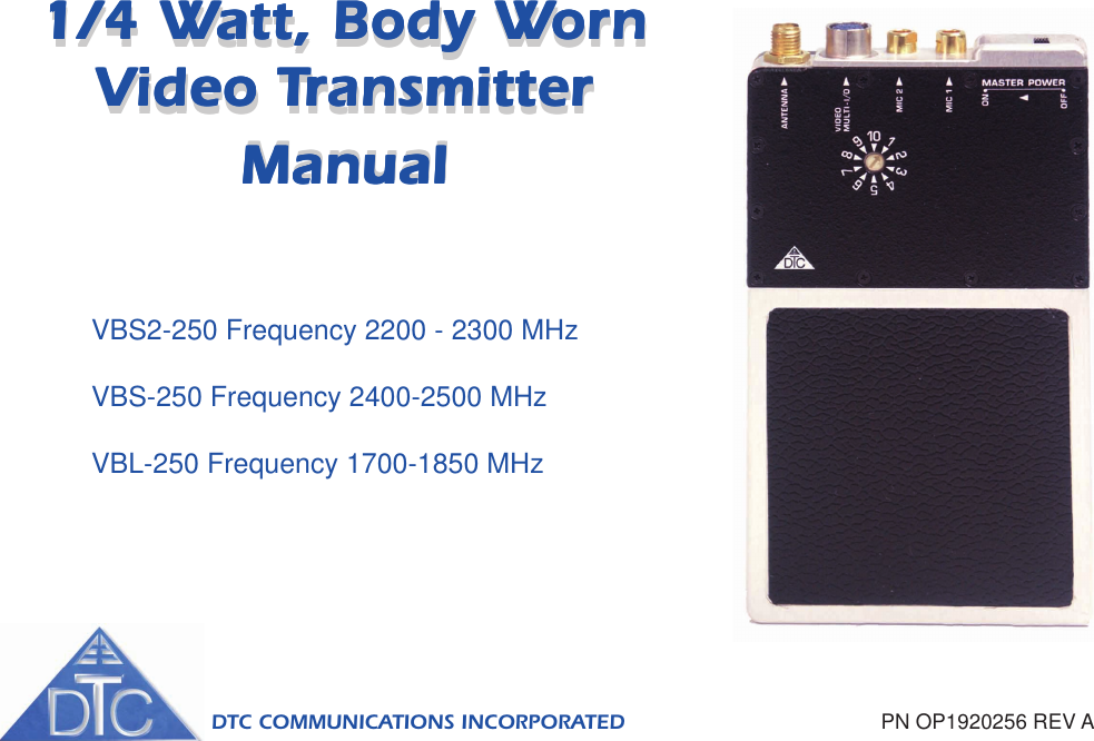
DTC Communications VXS250 Video Transmitter User Manual FCC Bodyworn
DTC Communications Inc. Video Transmitter FCC Bodyworn
UserManual.wiki
>
DTC Communications
>
VXS250 User Manual
>
Revised Manual
Contents
1.
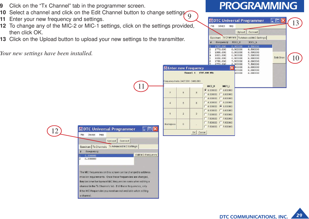
manual
2.
Appemdix A manual
3.
Manual
4.
Corrected manual Appendix A
5.
Revised Manual
Revised Manual
Navigation menu
Upload a User Manual
Namespaces
Wiki Guide
HTML
PDF
Info
Views
User Manual
Discussion / Help
Navigation