DUCANE Furnace/Heater, Gas Manual L0212120
User Manual: DUCANE DUCANE Furnace/Heater, Gas Manual DUCANE Furnace/Heater, Gas Owner's Manual, DUCANE Furnace/Heater, Gas installation guides
Open the PDF directly: View PDF ![]() .
.
Page Count: 22
I
lUtta"
Heating and Hir
Conditioning
Ducane Heating Division, The Ducane Company Inc., Blackville, SC 29817
CMP" A" SERIES
INSTALLATION INSTRUCTIONS
UPFLOW OR LEFT HORIZONTAL
GAS-FIRED CONDENSING
WARM AIR FURNACE
Issue 9939
WARNING
These instructions are intended to be used by qualified personnel who have been trained in installing
this:type of furnace. Installation by an unqualified person may lead to equipment damage and/or a
hazardous condition which may cause bodily injury and harm and, as such, at the so e d scret on of
the: manufacturer, the entire warranty may be voided and be of no further force and effect.
WARNING
The furnace cabinet must have an uninterrupted or unbroken electrical ground to minimize personal
injury if an. electrical fault should occur. The unit must also be electrically grounded in accordance
with.lo_ _es, Or in the absence of local codes, with the latest edition of the (U.S.) Nati6nal
Electrical:C0de ANS/NFPA No. 70 or CSA Standard C22.1; Part 1 Canadian Electrical Code, if an
external ee_?ical source s ut zed. DO NOT use gas piping as an electrical ground.
GENERAL INSTRUCTIONS
This furnace is design certified by CSA International as a category IV furnace andis dual certified as direct vent furnace (two pipe
system) using outside air for combustion or as a non-direct vent furnace (one pipe system) using air from inside the structure for
combustion.
It is shipped as a packaged unit, complete with burners and controls, and requires aline voltage (115V) connection to the junction box,
a thermostat hook-up as per the wiring diagram, a gas line connection, and a condensate drain connection. This furnace can be installed
in either upflow or horizontal 0eft) airflow positions. Do not install this furnace outdoors or use for temporary construction heating.
This furnace has been designed to interface with split system cooling equipment (approved by a nationally reco_lized testing
laboratory) so as to provide "year round air conditioning". The blower has been sized for both heating and cooling and the furnace
controls include a cooling fan relay.
The furnace installation must conform with local building codes or in the absence of local codes, with the latest edition of the (U.S.)
National Fuel Gas Code ANSI Z223.1 (NFPA-54) or Canadian Installation Codes CAN/CGA-B 149.
For complete information on installation standards consult the (U.S.) National Fuel Gas Code, obtainable from the National Fire
Protection Association, Inc., Batterymarch Park, Quincy, MA 02269 or the American Gas Association, 1515 Wilson Boulevard Arlington,
VA 22209 or the Canadian installation codes obtainable from Canadian Standards Association, 178 Rexdale Boulevard, Etobicoke,
Ontario, Canada M9W 1R3.
This furnace is designed for a minimum continuous return-air temperature of 60°F dB or intermittent operation down to 55*F dB such
as when used with a night setback thermostat. Return-air must not exceed a maximum continuous temperature of 85"F dB.
These instructions are written for individual residential installation only. For multi-unlt installations, please contact
manufacturer for recommendations.
20246506 Issue 9939 Page I of 22
LOCATION /PLACEMENT
Site Selection: This furnace may be located in an attic, closet, basement, crawl space, alcove, garage or suspended fromtheceiling of a
utility room or basement. Select a location that will meet all requirements for safety, clearances, ventilation and combustion air, ductwork
design, gas piping, electrical wiring and venting.
Clearances: The following minimum clearances, or greater, must be provided between the furnace and adjacent construction.
TableI. 2 MINIMUM INSTALLATION CLEARANCES
"UPFLOW" POSITION "HORIZONTAL (LEFI')" POSITION
Suitable for alcove or closet installation';"on combustible flooring Suitable for attic, alcove or closet installationt on combustible
at minimum clearance from adjacent consWuction not less that the flooring at minimum clearance from adjacent construction not less
following: that the following:
* Line contact only permissible between lines formed by intersection
of the top and two sides of the furnace jacket and building joist,
studs, or framing.
Top Sides Back Front Vent ;
2" 1" 1" 3" 0"
tFor closet installation see Air for Combustion and Ventilation.
The furnace should not be connected to an operational
chimney. The furnace should also be located as near to the center
of the air distribution system as possible, and should be installed
level.
This furnace may be installed on non-combustible flooring or
on wood flooring, however, it must not be installed directly on
carpeting, tile or any other combustible material.
In a horizontal position, line contact is only permissible
between lines formed by the intersection of the furnace top and the
front and bank sides and building joists, studs or framing (See
Figure 2.2).
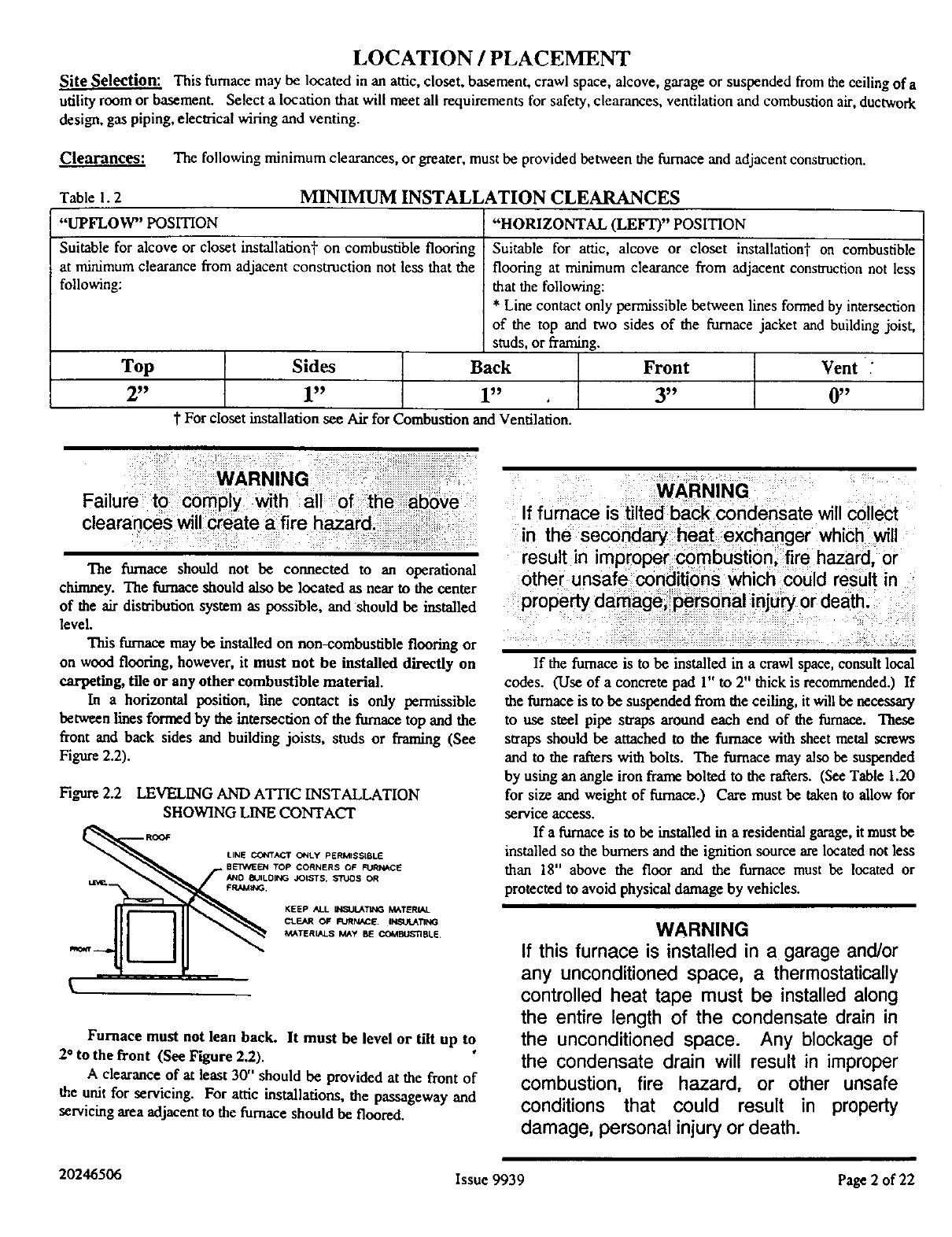
Figure 2.2 LEVELING AND ATTIC INSTALLATION
SHOWING LINE CONTACT
ROOF LINE CONTAC_r O¢4Ly PERMISSIBLE
BETV_I_I TOP CORNERS OF FURNACE
N4D 8UILDII_ JOISTS, :S'_JOS OR
KEEP ALL INSULATING MATERIAL
CLEAR OF FURNACE. Ill'JIlTING
MATERIt_I.S MAy BE COCdI_JS11BLE.
\
Furnace must not lean back. It must be level or tilt up to
2* to the front (See Figure 2.2).
A clearance of at least 30" should be provided at the front of
the unit for servicing. For attic installations, the passageway and
servicing area adjacent to the furnace should be floored.
WARNING
If furnace is tilted back condensate will collect
in the secondary heat exchanger which will
result in improper combustion, fire hazard, or
other unsafe conditions which could result in
property damage_ personal injury or death.
If the furnace is to be installed in acrawl space, consult local
codes. (Use of a concrete pad 1" to 2" thick is recommended.) If
the furnace is to be suspended from the ceiling, it will be necessary
to use steel pipe straps around each end of the furnace. These
straps should be attached to the furnace with sheet metal screws
and to the rafters with bolts. The furnace may also be suspended
by using an angle iron frame bolted to the rafters. (See Table 1.20
for size and weight of furnace.) Care must be taken to allow for
service access.
If a furnace is to be installed in a residential gara_, it must be
installed so the burners and the ignition source are located not less
than 18" above the floor and the furnace must be located or
protected to avoid physical damage by vehicles.
WARNING
If this furnace is installed in a garage and/or
any unconditioned space, a thermostatically
controlled heat tape must be installed along
the entire length of the condensate drain in
the unconditioned space. Any blockage of
the condensate drain will result in improper
combustion, fire hazard, or other unsafe
conditions that could result in property
damage, personal injury or death.
20246506 Issue 9939 Page 2 of 22
WARNING
Do not place combustible material on the
furnace jacket. Failure to comply with this
warning will create a fire hazard.
WARNING
This furnace is not watertight and is not
designed for outdoor installation. This
furnace shall be installed in such a manner
as to protect the electrical components from
water. Outdoor installation would lead to a
hazardous electrical condition and to
prematu're furnace failure.
Air for Combustion and Ventilation:
Contaminated CombustionAir If the furnace is to be
installed in a structure defined as having contaminated combustion
air, the furnace must use the direct vent (two pipe) configuration
using non-contaminated outside air for combustion. Allowing
exposure to substances containing chlorine or fluoride could harm
the furnace. Substances to avoid include, but are not limited to:
Permanent wave solutions
Chlorinated waxes and cleaners
Chlorine based swimming pool chemicals
Water softening chemicals
De-icing salts or chemical
Carbon tetrachloride
Halogen type refrigerants
Cleaning solvents (such as perchloroethylene)
Printing inks, paint removers, varnishes, etc.
Hydrochloric acid
Cements and glues
Antistatic fabric softeners for clothes dryers
Masonry acid washing materials
WARNING
Contaminated combustion air may cause
premature failure of the heat exchanger that
may lead to a hazardous condition and/or
bodily harm, or loss of life.
Adequate Ventilation and Combustion Air This
section is provided to give guidelines for the introductionof air for
ventilation and combustion air. The total quantity of air provided
to the installation area must equal the requirements of all gas
appliances in the area.
Adequate facilities ior providing air for combustion and
ventilation must be provided in accordance with the latest editiou
of section 5.3. Air for Combustion and Ventilation, of the National
Fuel Gas Code ANSI Z223.1 or Sections 7.2. 7.3 or 7.4 of
CAN/CGA B149 Installation Codes, or applicable provisions of
the local building codes.
The furnace shall be installed in a location in which the
facilities for ventilation permits satisfactory combustion of gas,
proper venting and maintenance of ambient temperature at safe
limits under normal conditions of use. The furnace shall be located
so as not to interfere with proper circulation of air.
In addition to air needed for combustion, ventilation in the
form of process air must be provided as required for: cooling of
equipment or material, controlling dew point, heating, drying,
oxidation or dilution, safety exhaust and odor control. Air must be
supplied for ventilation, including all air required for comfort and
proper working conditions for personnel. Direct venting (two
pipe) allows for the combustion air to be supplied directly to
the _rnace from the outdoors. Ventilation needs only to be
considered when furnace is installed as direct vent (two pipe).
Non-direct venting (one pipe) requires both combustion and
ventilation air requirements from the furnace location. For
purposes of this instrncdon the following definitions apply:
Unconfined Space: A space whose volume is not less than
50 cubic feet per 1000 Btu per hour of
the aggregate input rating of all
appliances installed in that space.
Rooms communicating directly with
the space in which the appliances are
installed, through openings not
furnished with doors, are considered a
part of the unconfined space.
Confined Space: Aspace whose volume is less than 50
cubic feet per 1000 Btu per hour of the
aggregate input rating of all appliances
installed in that space.
If the installation area meets the definition of "Unconfined
Space" and does not have additional air requirements as described,
the furnace may be installed without making special provisions for
combustion and ventilation air.
CAUTION
Whenever this furnace is installed in an area
along with one or more gas appliances, the
total Btu input of all appliances must be
included when determining the free area
requirements for combustion and ventilation
air openings.
20246506 Issue 9939 Page 3 of 22
If ventilation and/or combustion air must be supplied to the
•'Confined Space" from inside the building structure, two
permanent openings to an additional room of sufficient volume
as to combine the volumes of the spaces to meet the criteria for
an "Unconfined Space" must be created. Each opening must
have a free area of not less than one square inch per 1000 Btu per
hour of total input of all appliances within the "'Confined Space"
(but not less than 100 square inches). These openings must be
located 12 inches from the top and bottom of the furnace area
respectively and must be at least 3 inches long on the smaller side
of the opening. Neither opening can be blocked at any time.
If ventilation and/or combustion air must be supplied to the
"Confined Space" from outslde the building structure, two
permanent openings to the outdoors must be created. Each
opening must have a free area of not less than one square inch per
4000 Btu per hour of total input of all appliances within the
"Confined Space". These openings must be located 12 inches
from the top and bottom of the furnace area respectively. Neither
opening can be blocked at any time.
When ducts are used to supply air, they must be of the same
cross sectional area as the free area of the openings to which they
connect. The minimum dimension of rectangular air ducts must
not be less than 3 inches.
;_ARNING :
DO not biock tfie com6usti6_ or ventilatid_: a!_ ::
openings,in:tlie furnace. Any: bloCkag_:,_ii:
result in impfope_ cOmbustion and ma_:re_:_lt :
n; :
WARNING
If the blocked vent pressure switch (P1)
activates to shut the furnace down, the vent
system must be checked and cleared.
Failure to do so may result in serious bodily
harm or nuisance furnace shutdown and/or
a hazardous condition that may lead to
property damage, personal injuryor death.
WARNING
If the blocked drain pressure switch (P2)
activates to shut the furnace down, do not
attempt to operate the furnace until the drain
line is checked for blockage. Failure to clear
the drainage system could lead to nuisance
furnace shutdown and/or hazardous
conditions that may lead to property
damage personal injury or death,
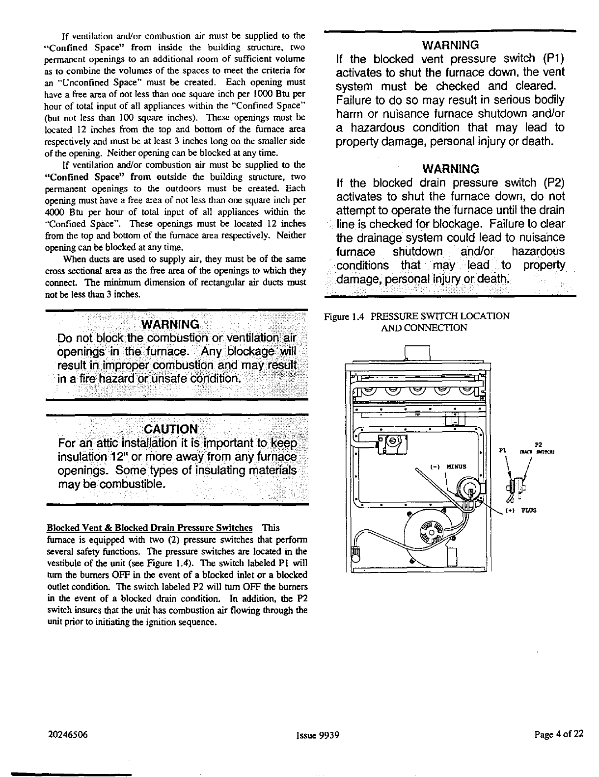
Figure 1.4 PRESSURE SWITCH LOCATION
AND CONNECTION
may be combustible.
Blocked Vent &Blocked Drain Pressure Switches This
furnace is equipped with two (2) pressure switches that perform
several safety functions. The pressure switches are located in the
vestibule of the unit (see Figure 1.4). The switch labeled P1 will
turn the burners OFF in the event of a blocked inlet or a blocked
outlet condition. The switch labeled P2 will turn OFF the burners
in the event of a blocked drain condition. In addition, the P2
switch insures that the unit has combustion air flowing through the
unit prior to initiating the ignition sequence.
I °
| MINUS
P2
Y
PLUS
20246506 Issue 9939 Page 4of 22

INSTALLATION
In all direct vent (two pipe) instances, the vent outlet shall be installed so as to be in the same amlosphcric pressure zone as the
combustion air intake, When installed, the furnace must be electrically grounded in accordance with local codes or. in the absence of local
codes, with the (U.S.) National Electrical Codes, ANSI/NFPA 70or CSA Standard C22.1; Part 1 Canadian Electrical Code. To properly
install the field wiring of this unit refer to Figures 1.21 & 1.22. In all instances, the wiring to be done, and any replacement of wire shall
conform with the temperature limitation for Type T wire [630F rise (350C)].
To Prepare Unit for Installation:
General Requirements
Regardless of which airflow direction that the furnace is
installed, the following steps are required:
1. The electrical connections and the thermostat connections are
made at the openings on either side panel of the unit in the
control box area. Either side may be used, as convenient, but
the provided hole plugs should be inserted in the unused holes.
2. A left, right, or bottom return air opening must be used as
determined by the layout of the installation. An externally
mounted air filter is required.
3. This furnace has a two piece bottom panel. For bottom or end
duct return, remove the back portion of the bottom panel by
removing the four (4) screws---2 on each side toward the back
of the furnace. (See Figure 1.5) Tilt furnace toward the front,
the back portion of the panel will drop down. Then the back
portion can be removed by pulling toward the back of the
furnace. Refer to Figure 2.20 for ductwork sizing.
Figure 1.5 BOTTOM PANEL REMOVAL
Knockouts are provided on both sides of the furnace to
facilitate the cutout required to the return air ductwork. Furnace
cutouts must be the full size specified by the corner markers.
Undersized cutouts will adversely affect the airflow capability
of the furnace and could cause overheating of the heat
exchanger.
The following recommendations should be followed when
installing the ductwork:
1. Install locking-type dampers in all branches of the individual
ducts to balance out the system. Dampers should be adjusted
to impose the proper static at the outlet of the furnace.
2. Noncombustible flexible duct connectors are recommended to
connect both the supply and return duetS to the furnace.
3. In cases where the return air grille is located close to the
blower inlet, there should be at least one 90° air turn between
blower and retUrn grille. Further reduction in sound can be
accomplished by installing acoustical air taming vanes and/or
lining the inside of the duct with acoustical material.
4. It is recommended that the supply duct be provided with a
removable access panel. This opening shall be accessible
when the furnace is installed and shall be of such a size that
the heat exchanger can be viewed for possible openings using
light assistance or a probe can be inserted for sampling the air
stream. The access panel shall be designed so as mprevent
leaks when locked in position, If an air conditioning coil is
installed, the access panel to the coil can be used for this
purpose.
4. The flue may exit the cabinet either through the right or the
left side panel, depending on the requirements of the
installation. If the unit is installed in a horizontal-left
clischarge position, it is required to exit through the right side
panel, so the flue is pointing straight up when the unit is
installed. See figures 2.8 and 3.8 for configurations.
WARNING
When supply ducts carry air circulated by the
furnace to areas outside the spaces containing the
furnace, the return air shall also be handled by a
duct sealed to the furnace casing and terminating
outside the space containing the furnace. Incorrect
ductwork termination and sealing will create a
hazardous condition that could lead to bodily
harm.
.Ductwork Recommendation:
The proper sizing of warm air ducts is necessary to insure
satisfactory heating operation. Ductwork should be in accordance
with the latest editions of U.S. NFPA-90A (Air Conditioning
Ssm_S.x.E_.._)and NFPA-90B (Warm Air Heating and Air
Conditioning Systems) or Canadian equivalent.
The supply ductwork should be attached to the flanged
opening provided at the discharge end of the furnace. See Figure
2.20 for the dimensions of this opening.
CAUTION
Air openings, intake and outlet pipes, retum air
grilles and warm air registers must not be
obstructed.
When installing the furnace with cooling equipment for year
round operation, the following recommendations must be followed
for series or parallel air flow:
20246506 Issue 9939 Page 5 of 22
1. In seriesflow applications, the coil is mounted after the
furnace in an enclosure in the supply air stream. The furnace
blower is used for both heating and cooling airflow.
2. In parallel flow installation, dampers must be provided to
direct air over the furnace heat exchanger when heat is desired
and over the cooling when cooling is desired.
IMPORTANT: The dampers should be adequate to prevent
cooled air from entering the furnace, and if
manually operated, must be equipped with
means to prevent operation of either the cooling
unit or furnace unless the damper is in the full
cool or full heat position.
WARNING
The coil MUST be installed on the air discharge
side of the furnace. Under no circumstances should
the air flow be such that cooled, conditioned air can
pass over the furnace heat exchanger. This will
cause condensation in the heat exchanger and
possible failure ,of the heat exchanger that could
lead to a fire hazard and/or hazardous conditions
that may lead to bodily harm. Heat exchanger
failure due to improper installation may not be
covered by warranty.
Gas piping shall be of such size and so installed as to provide
a supply of gas sufficient to meet maximum demands without
undue loss of pressure between the gas meter and the furnace. It is
recommended that the gas line to the furnace shall be a separate
line direct from the meter, unless the existing gas line is of ample
capacity. Refer to gas pipe capacity table in the National Fuel Gas
Code (ANSI 7-,223.1)or the CANI-B 149 Installation Code.
Use a joint compound (pipe dope) that is resistant to the action
of liquefied petroleum gases or any other chemical constituents of
the gases to be conducted through the piping.
NOTE: In order to make proper input adjustments, minimum and
maximum gas supply pressure limits shown on the rating
plate must not be exceeded.
Before any system of gas piping is finally put into service, it
should be carefully tested to determine if it is gas tight. Check all
piping for leaks using soapy water and a brush. The piping must
stand a pressure of six (6) inches of mercury for a period of ten
(10) minutes or as required by local authority.
WARNING
The furnace and its individual shutoff valve must
be disconnected from the supply piping system
during any pressure testing of that system at test
pressures in excess of 1/2 PSIG (3.5kPa or
14"w.c.).
The furnace must be isolated from the gas supply
piping system by closing its individual manual
shutoff valve during any pressure testing of the
gas supply piping system at pressures equal to or
less than 1/2 PSIG (3.5kPa or 14"w.c.). Failure to
follow the above procedures couId lead to a
hazardous condition and bodily harm. o
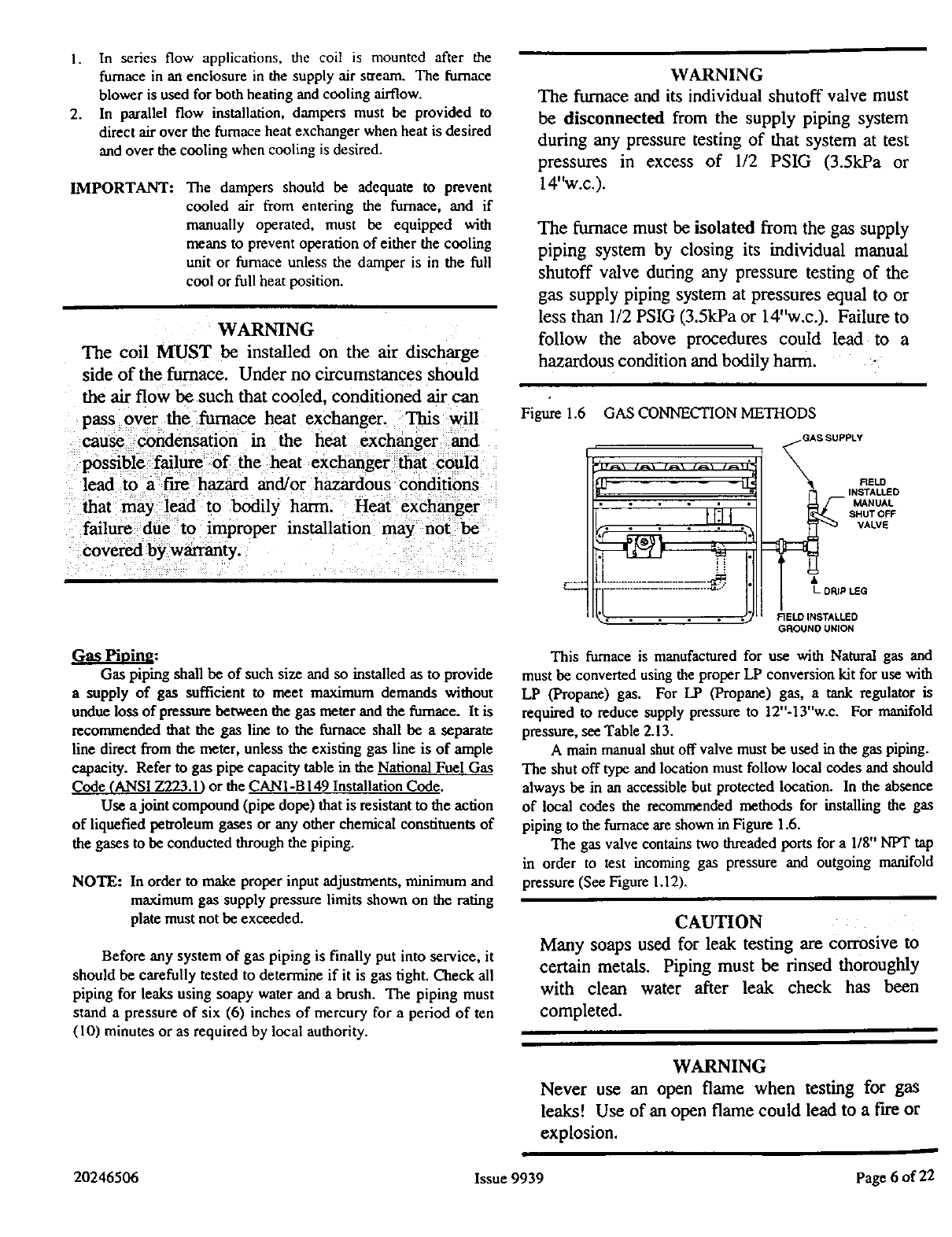
Figure 1.6 GAS CONNECTION METHODS
,_LTS
r• • , • •
FIELD
SHUT OFF
VALVE
l'I_ DRIP tea
FIELD INSTALLED
GROUND UNION
This furnace is manufactured for use with Natural gas and
must be converted using the proper LP conversion kit for use with
LP (Propane) gas. For LP (Propane) gas, a tank regulator is
required to reduce supply pressure to 12"-13"w.c. For manifold
pressure, see Table 2.13.
A main manual shut off valve must be used in the gas piping.
The shut off type and location must follow local codes and should
always be in an accessible but protected location. In the absence
of local codes the _conm_nded methods for installing the gas
piping to the furnace are shown in Figure 1.6.
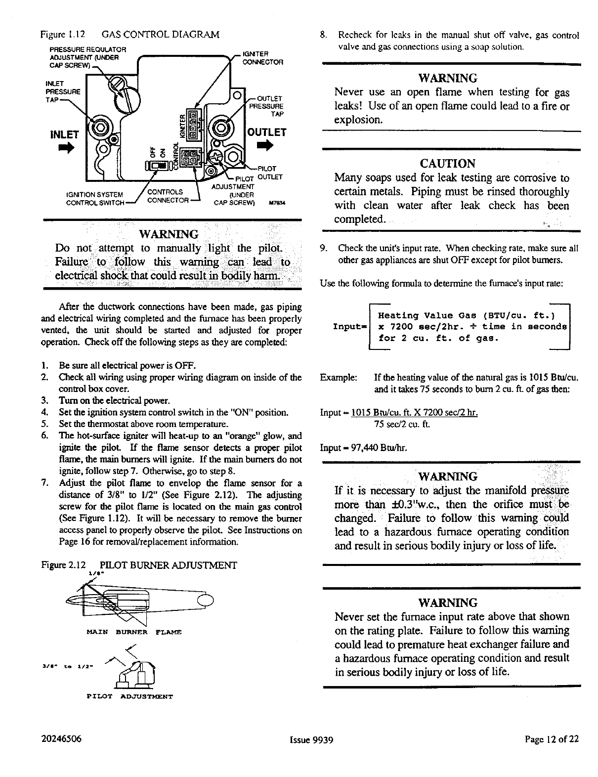
The gas valve contains two threaded ports for a 1/8" NPT tap
in order to test incoming gas pressure and outgoing manifold
pressure (See Figure 1.12).
CAUTION
Many soaps used for leak testing are Corrosive to
certain metals. Piping must be rinsed thoroughly
with clean water after leak check has been
completed.
WARNING
Never use an open flame when testing for gas
leaks! Use of an open flame could lead to a fire or
explosion.
20246506 Issue 9939 Page 6 of 22
FAectrical:
The control system depends on the correct polarity of the
power supply. Connect "hot" wire (H) and "ground" wire "G'"' as
shown in Figures 1.21 & 1.22. Reference table 1.20 for furnace
over current protection, current rating and wire size. Use copper
wire only for ll5V-supply service to unit. When replacing any
original internal wiring, use only 105°C, 16 AWG copper wire.
Instructions for wiring the thermostat are packed in the
thermostat (field supplied) box. Make the thermostat connections
as shown in Figures 1.21 & 1.22 at the 24-volt terminal board
located in the control box.
When installing optional accessories to this appliance, follow
the manufacturer's installation instructions included with the
accessory. Other than wiring for the thermostat, a minimum of
type T (63°F rise) must be used.
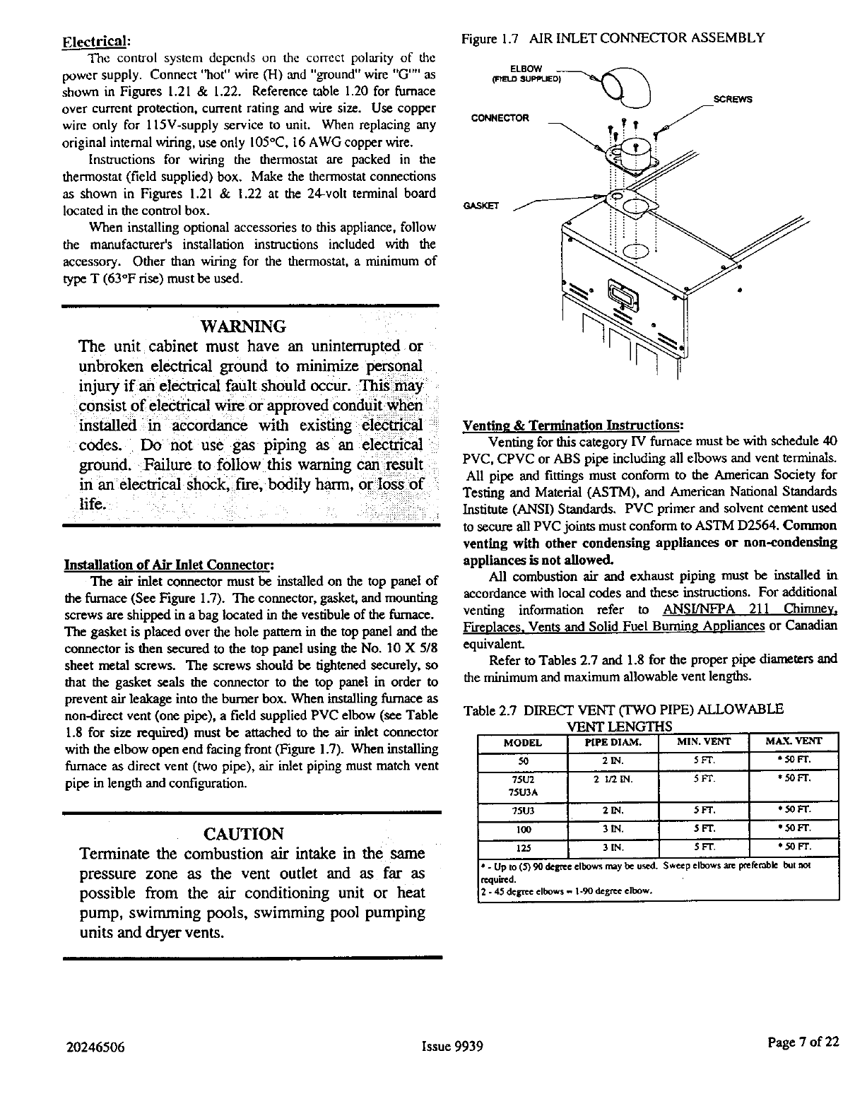
Figure 1.7 AIR INLET CONNECTOR ASSEMBLY
CONNE_OR
GASKET
WARNING
The unit cabinet must have an uninterrupted or
unbroken electrical ground to minimize personal
injury if an electrical fault should occur. This may
consist of electrical wire or approved conduit when
installed in accordance with existing electrical
codes. Do not use gas piping as an electrical
ground. Failure to follow this warning can result
m an electrical shock, fire, bodily harm. or loss of
life.
Installation of Air Inlet Connector:
The air inlet connector must be installed on the top panel of
the furnace (See Figure 1.7). The connector, gasket, and mounting
screws are shipped in a bag located in the vestibule of the furnace.
The gasket is placed over the hole pattern in the top panel and the
connector is then secured to the top panel using the No. 10 X 5/8
sheet metal screws. The screws should be tightened securely, so
that the gasket seals the connector to the top panel in order to
prevent air leakage into the burner box. When installing furnace as
non-direct vent (one pipe), a field supplied PVC elbow (see Table
1.8 for size required) must be attached to the air inlet connector
with the elbow open end facing front (Figure 1.7). When installing
furnace as direct vent (two pipe), air inlet piping must match vent
pipe in length and configuration.
CAUTION
Terminate the combustion air intake in the same
pressure zone as the vent outlet and as far as
possible from the air conditioning unit or heat
pump, swimming pools, swimming pool pumping
units and dryer vents.
Venting &Termination Instructions:
Venting for this category IV furnace must be with schedule 40
PVC, CPVC or ABS pipe including all elbows and vent terminals.
All pipe and fittings must conform to the American Society for
Testing and Material (ASTM), and American National Standards
Institute (ANSI) Standards. PVC primer and solvent cement used
to secure all PVC joints must conform to ASTM D2564. Common
venting with other condensing appliances or non-condensing
appliance* is not allowed.
All combustion air and exhaust piping must be installed in
accordance with local codes and these instructions. For additional
venting information refer to ANSI/NFPA 211 Chimney,
Fireplaces, Vents and Solid Fuel Bumin_ Anoliances or Canadian
equivalenL
Refer to Tables 2.7 and 1.8 for the proper pipe diameters and
the minimum and maximum allowable vent lengths.
Table 2.7 DIRECT VENT (TWO PIPE) ALLOWABLE
VENT LENGTHS
MODEL PIPEDIAM.
50 2_.
75U2 2 1_.
75U3A
75W 2_.
1_ 3_.
125 3_.
MIN. VENT MAX. VENT
5FT. *:;OFT.
5FT. *50 FT.
5FT. *50 FT.
5zr. * 50 F'r.
5FT. *50FT.
* - Up to (5) 90 degree elbows may be used. Sweep elbows are poeretable but not
required.
2- 45 degree elbows - 1-90 degree elbow.
20246506 Issue 9939 Page 7of 22
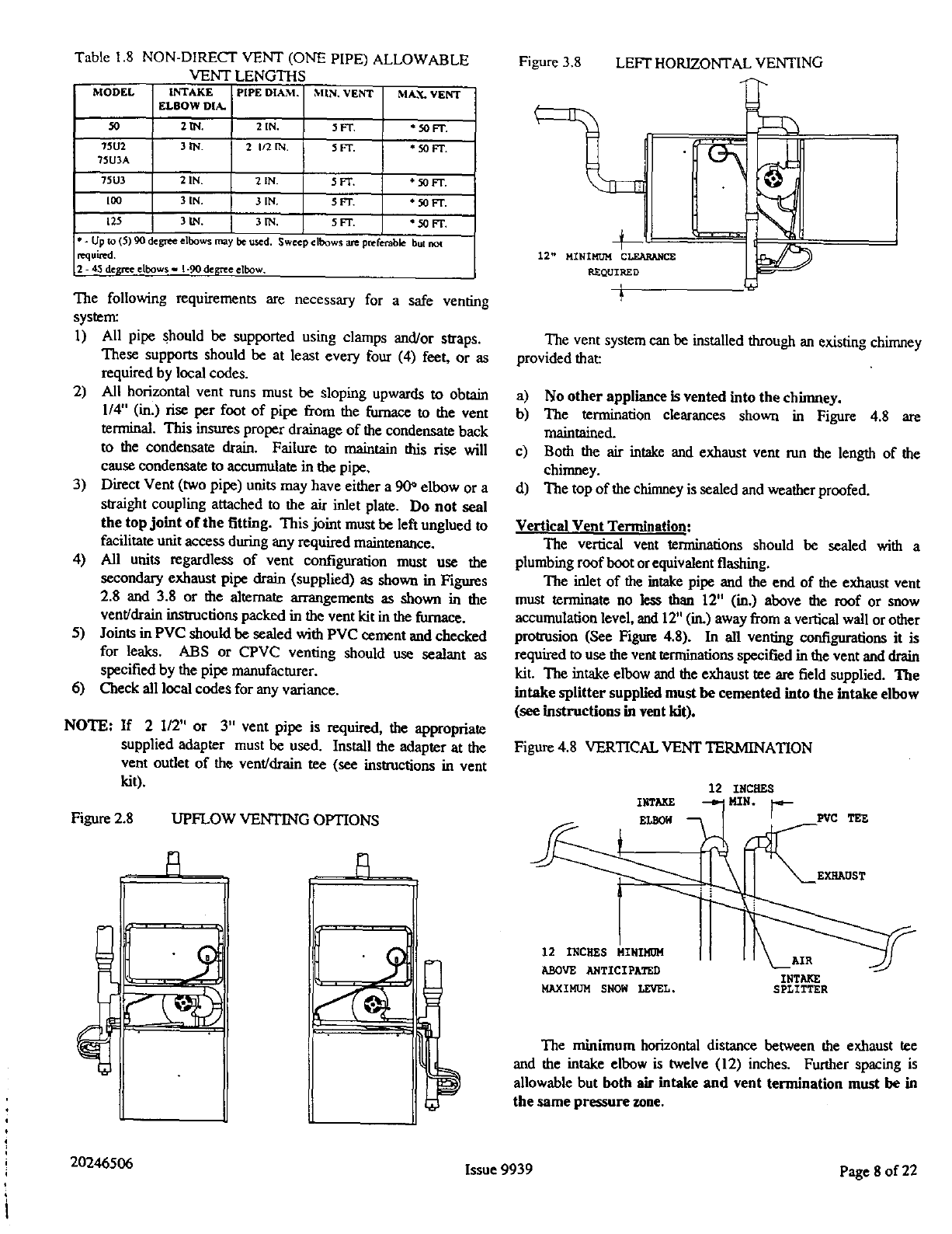
Table 1.8 NON-DIRECT VENT (ONE PIPE) ALLOWABLE
VENT LENGTHS
MODEL INTAKE PIPE DIAM.
ELBOW DIA.
50 2l/q. 2IN.
7502 3 IN. 2I/2 IN.
7503A
75U3 2 IN. 2 IN.
ICO 3 IN. 3 IN.
125 3IN. 31N.
,%nN. VENT MAX. VENT
5FT. *50 Ft.
5FT. *50 FT.
5FT. *50 FT.
5FT. *50FL
5FT. * 50 FT.
"- Up to (5) 90 degree elbows may be used. Sweep elbows ave pntretable but not
requited.
2- 45 de_,rteelbows - 1-90 de_'ee elbow.
The following requirements are necessary for a safe venting
system:
1) All pipe should be supported using clamps and/or straps.
These supports should be at least every four (4) feet, or as
required by local codes.
2) All horizontal vent runs must be sloping upwards to obtain
1/4" (in.) rise per foot of pipe from the furnace to the vent
terminal. This insures proper drainage of the condensate back
to the condensate drain. Failure to maintain dfis rise will
cause condensate to accumulate in the pipe,
3) Direct Vent (two pipe) units may have either a 90* elbow or a
straight coupling attached to the air inlet plate. Do not seal
the top joint of the fitting. This joint must be left unglued to
facilitate unit access during any required maintenance.
4) All units regardless of vent configuration must use the
secondary exhaust pipe drain (supplied) as shown in Figures
2.8 and 3.8 or the alternate arrangements as shown in the
vent/drain instmcdous packed in the vent kit in the furnace.
5) Joints in PVC should be sealed with PVC cement and chocked
for leaks. ABS or CPVC venting should use sealant as
specified by the pipe manufacturer.
6) Cheek all local codes for any variance.
NOTE: If 2 I/2" or 3" vent pipe is required, the appropriate
supplied adapter must be used. Install the adapter at the
vent outlet of the vent/drain tee (see instructions in vent
kit).
Figure 2.8 UPFLOW VENTING OPTIONS
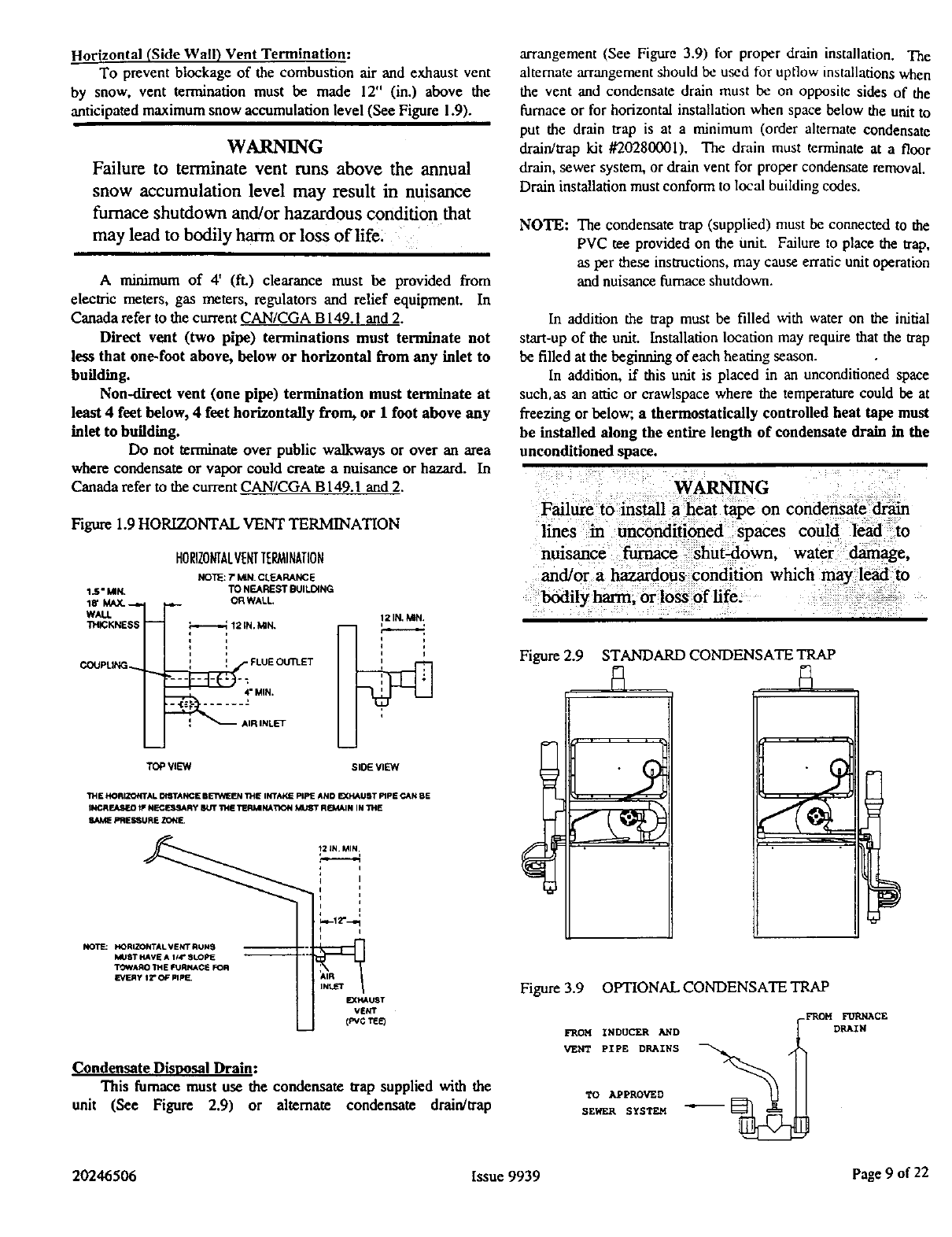
Figure 3.8 LEFT HORIZONTAL VENTING
12" MINIMUM CLEARANCE
P_EQUIRED
The vent system can be installed through an existing chimney
provided that:
a) No other appliance is vented into the chimney.
b) The termination clearances shown in Figure 4.8 are
maintained.
c) Both the air intake and exhaust vent run the length of the
chimney.
d) The top of the chimney is sealed and weatherproofed.
Vertical Vent Termination:
The vertical vent terminations should be sealed with a
plumbing roof boot or equivalentflashing.
The inlet of the intake pipe and the end of the exhaust vent
must terminate no less than 12" (in.) above the roof or snow
accumulation level, and 12" (in.) away from a vertical wall or other
protrusion (See Figure 4.8). In all venting configurations it is
required to use the vent terminations specified in the vent and drain
kit. The intake elbow and the exhaust tee are field supplied. ']['he
intake splitter supplied must be cemented into the intake elbow
(see instructions in vent kit).
Figure 4.8 VERTICAL VENT TERMINATION
12 INCHES
INTAKE MIN.
EI_ [ PVC TEE
EXHAUST
12 INCHES MINIMOM
ABOVE ANTICIPATED
MAXIMUM SNOW LEVEL. INTA_
SPLITTER
The minimum horizontal distance between the exhaust tee
and the intake elbow is twelve (12) inches. Further spacing is
allowable but both air intake and vent termination must be in
the same pressure zone.
20246506 Issue 9939 Page 8 of 22
Horizontal (Side Wall) Vent Termination:
To prevent blockage of the combustion air and exhaust vent
by snow, vent termination must be made 12" (in.) above the
anticipated maximum snow accumulation level (See Figure 1.9).
WARNING
Failure to terminate vent runs above the annual
snow accumulation level may result in nuisance
furnace shutdown and/or hazardous condition that
may lead to bodily harm or loss of life.
A minimum of 4' (ft.) clearance must be provided from
electric meters, gas meters, regulators and relief equipment. In
Canada refer to the current CAN/CGA B 149.1 and 2.
Direct vent (two pipe) terminations must terminate not
less that one-foot above, below or horizontal from any inlet to
building.
Non-direct vent (one pipe) termination must terminate at
least 4 feet below, 4 feet horizontally from, or 1 foot above any
inlet to building.
Do not terminate over public walkways or over an area
where condensate or vapor could create a nuisance or hazard. In
Canada refer to the current CAN/CGA B149.1 and 2.
Figure 1.9 HORIZONTAL VENT TERMINATION
HORIZONTALVENTTERMINATION
NOTE: TMIN. CLEARANCE
TO NEAREST BUILDING
OR WALL.
1.5" MIN.
18" MAX._
WALL 12 IN, ,VdN.
IHICKNESS -- _ 12 IN. I_N. i
l I J
i t i i
_FLUE Otm_ET _
COJJPLING _" "" .... _" MIN. !
_AIR INLET
m
TOP VIEW SlOE VIEW
IH£ HORIZONTAL OI_TANCE IIETVCEEN THE INTAKE PIPE AND EXHAUST PIpE CAN 8E
INCRFJtSEO IF N_RY _THE TERIdl NA'_ON MUST RI_dAIN IN THE
PRESSURE ZONE.
;,
i i
i
i J
MUST HAVE A 114' SLOPE
"_'JWAAO I_E FURNACE _R
VEto"
Condensate Disposal Drain:
This furnace must use the condensate trap supplied with the
unit (See Figure 2.9) or altemate condensate drain/trap
arrangement (See Figure 3.9) for proper drain installation. The
ahemate arrangement should be used for uptTow installations when
the vent and condensate drain must be on opposite sides of the
furnace or for horizootal installation when space below the unit to
put the drain trap is at a minimum (order alternate condensate
drain/trap kit #20280001). The drain must terminate at a floor
drain, sewer system, or drain vent for proper condensate removal.
Drain installation must conform to local building codes.
NOTE: The condensate trap (supplied) must be connected to the
PVC tee provided on the unit. Failure to place the trap,
as per these instructions, may cause erratic unit operation
and nuisance furnace shutdown.
In addition the trap must be filled with water on the initial
start-up of the unit. installation location may require that the trap
be filled at the beginning of each heating season.
In addition, if this unit is placed in an unconditioned space
such,as an attic or crawlspace where the temperature could be at
freezing or below; athermostatically controlled beat tape must
be installed along the entire length of condensate drain in the
unconditioned space.
WARNING
Failure to install a heat tape on condensate drain
lines in unconditioned spaces could lead to
nuisance furnace shut-down, water damage,
and/or a hazardous condition which may lead to
bodily harm, or loss of life.
Figure 2.9 STANDARD CONDENSATE TRAP
Figure 3.9 OPTIONAL CONDENSATE TRAP
FROM INDUCER A//D
VENT PIPE DRAIHS
TO APPROVED
SEWER SYSTEM
_FROM FURNACE
DRAIN
20246506 Issue 9939 Page 9of 22
Flue Pipe Installation:
NOTE: Make sure of alignment and fit, before gluing pieces
in place!
To Install With Right Flue Exit:
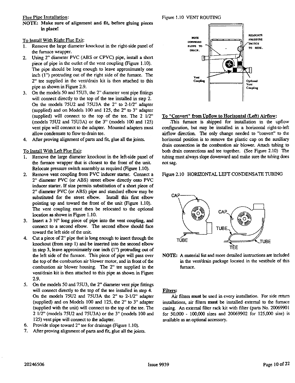
1. Remove the large diameter knockout in the right-side panel of
the furnace wrapper.
2. Using 2" diameter PVC (ABS or CPVC) pipe, install a short
piece of pipe in the outlet of the vent coupling (Figure 1.10).
The pipe should be long enough to leave approximately one
inch (1") protruding out of the right side of the furnace. The
2" tee supplied in the vent/drain kit is then attached to this
pipe as shown in Figure 2.9.
3. On the models 50 and 75U3, the 2" diameter vent pipe fittings
will connect directly to the top of the tee installed in step 2.
On the models 75U2 and 75U3A the 2" to 2-1/2" adapter
(supplied) and on Models 100 and 125, the 2" to 3" adapter
(supplied) will connect to the top of the tee. The 2 1/2"
(models 75U2 and 75U3A) or the 3" (models 1(30and 125)
vent pipe will connect to the adapter. Mounted adapters must
allow condensate to flow to drain tee.
4. After proving alignment of parts and fit, glue all the joints.
To Install With Left Flue Exit:
I. Remove the large diameter knockout in the left-side panel of
the furnace wrapper that is closest to the front of the unit.
Relocate pressure switch assembly as required (Figure 1.1(3).
2. Remove vent coupling from PVC inducer starter. Connect a
2" diameter PVC (or ABS) street elbow directly onto PVC
inducer starter. If size permits substitution of a short piece of
2" diameter PVC (or ABS) pipe and standard elbow may be
substituted for the street elbow. Install this first elbow
pointing up and toward the front of the unit (Figure 1.10).
The vent coupling must then be relocated to the optional
location as shown in Figure 1.10.
3. Insert a 3 W' long piece of pipe into the vent coupling, and
connect to a second elbow. The second elbow should face
toward the left side of the unit.
4. Cut a piece of 2" pipe that is long enough to insert throughthe
knockout (from step 1) and be inserted into the second elbow
in step 3, leave approximately one inch (1") protruding out of
the left side of the fairnace. This piece of pipe will pass over
the top of the combustion air blower motor, and in front of the
combustion air blower housing. The 2" tee supplied in the
vent/drain kit is then attached to this pipe as shown in Figure
2.9.
5. On the models 50 and 75U3, the 2" diameter vent pipe fittings
will connect directly to the top of the tee installed in step 4.
On the models 75U2 and 75U3A the 2" to 2-1/2" adapter
(supplied) and on Models 100 and 125, the 2" to 3" adapter
(supplied with the unit) will connect to the top of the tee. The
2 1/2" (models 75U2 and 75U3A) or the 3" (models 100 and
125) vent pipe will connect to the adapter.
6. Provide slope toward 2" tee for drainage (Figure 1.10).
7. After proving alignment of parts and fit, glue all the joints.
Figure 1.10 VENT ROUTING
NO'g'E
SLOp£ TO
DP_IN.
Vent
_LOC_'E
PKESS_£
/-SNITCK
TO FIE_E.
Optional
Vent
Cou#Ing
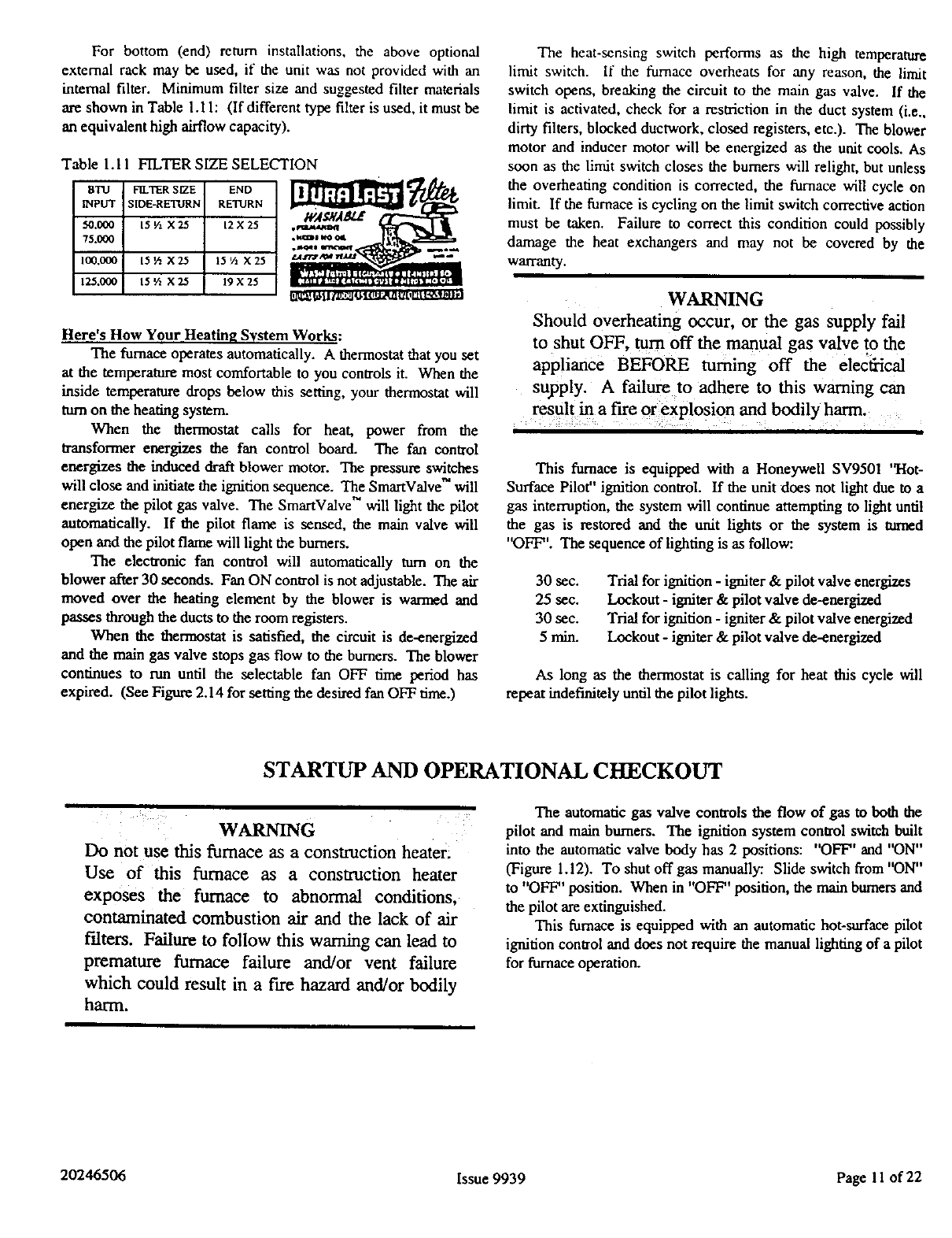
To "Convert" from Upflow to Horizontal (Left) Airflow:
,This furnace is shipped for installation in the upflow
configuration, but may be installed in a horizontal right-to-left
airflow direction. The only change needed to "convert" to the
horizontal position is to remove the plastic cap on the auxiliary
drain connection in the combustion air blower. Attach tubing to
both drain connections and tee together. (See Figure 2.10) The
tubing must always slope downward and make sure the tubing does
not sag.
Figure 2.10 HORIZONTAL LEFT CONDENSATE TUBING
cAP
T0o /
_TUBE
NOTE: A material list and more detailed instructions are included
in the vent/drain package located in the vestibule of this
furnace.
Filters:
Air filters must be used in every installation. For side return
installations, air filters must be installed external to the furnace
casing. An external filter rack kit with filter (parts No. 20069901
for 50,000 - 100,000 sizes and 20069902 for 125,000 size) is
available as an optional accessory.
20246506 Issue 9939 Page 10 of 22
For bottom (end) return installations, the above optional
external rack may be used, it" the unit was not provided with an
internal filter. Minimum filter size and suggested filter materials
are shown in Table 1.11: (If differant type filter is used, it must be
an equivalent high airflow capacity).
Table 1.11 FILTER SIZE SELECTION
B'IU FILTER SIZE END _g_
INPUT SIDE-RETURN RETURN
5"0.000 15 V1 X25 12X25
75.oooI
100.0(30 i 15 IA X 2.5 IS Vl X 25 t_arm din' na,ta t.=.
125.0001 15V2 X2.5 19X25
Here's How Your Heating System Works:
The furnace operates automatically. A thermostat that you set
at the temperature most comfortable to you controls it. When the
inside temperature drops below this setting, your thermostat will
turn on the heating system.
When the thermostat calls for heat, power from the
a'ansformer energizes the fan control board. The fan control
energizes the induced draft blower motor. The pressure switches
will close and inidate the ignition sequence. The SmartValve" will
energize the pilot gas valve. The SmartValve" will light the pilot
automatically. If the pilot flame is sensed, the main valve will
open and the pilot flame will light the burners.
The electronic fan control will automatically turn on the
blower after 30 seconds. Fan ON control is not adjustable. The air
moved over the heating element by the blower is warmed and
passes through the ducts to the room registers.
When the thermostat is satisfied, the circuit is de-energized
and the main gas valve stops gas flow to the burners. The blower
continues to run until the selectable fan OFF time period has
expired. (See Figure 2.14 for setting the desired fan OFF time.)
The heat-sensing switch performs as the high temperature
limit switch. If the furnace overheats for any reason, the limit
switch opens, breaking the circuit to the main gas valve. If the
limit is activated, check for a restriction in the duct system (i.e.,
dirty filters, blocked duct'work, closed registers, etc.). The blower
motor and inducer motor will be energized as the unit cools. As
soon as the limit switch closes the burners will relight, but unless
the overheating condition is corrected, the furnace will cycle on
limit. If the furnace is cycling on the limit switch corrective action
must be taken. Failure to correct this condition could possibly
damage the heat exchangers and may not be covered by the
walTanty.
WARNING
Should overheating occur, or the gas supply fail
to shut OFF, turn off the manual gas valve to the
appliance BEFORE turning off the electiical
supply. A failure to adhere to this warning can
result in a fire or explosion and bodily harm.
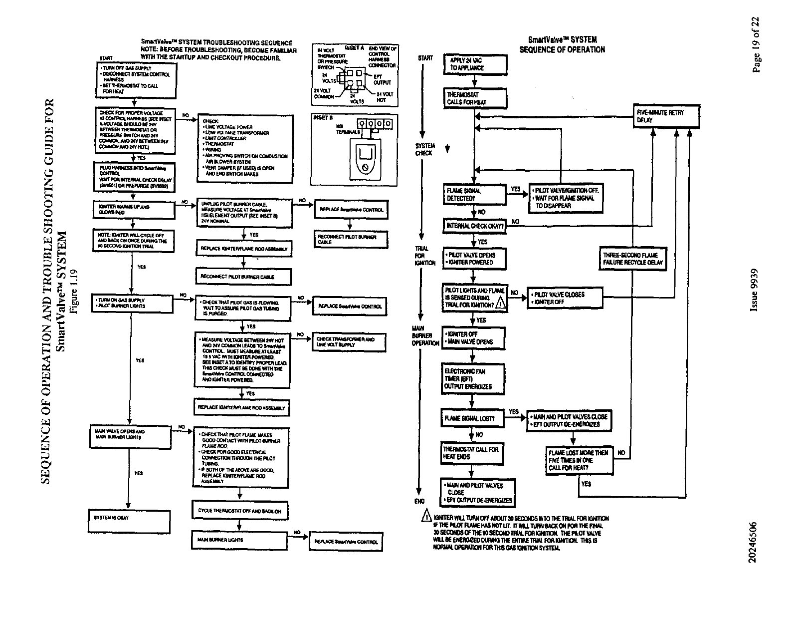
This furnace is equipped with a Honeywell SV9501 "Hob
Surface Pilot" ignition control. If the unit does not light due to a
gas interruption, the system will continue attempting to light until
the gas is restored and the unit lights or the system is turned
"OFF". The sequence of lighting is as follow:.
30 sec. Trial for ignition -igniter & pilot valve energizes
25 see. Lockout -igniter & pilot valve de-energized
30 sec. Trial for ignition - igniter & pilot valve energized
5 min. Lockout - igniter & pilot valve de-energized
As long as the thermostat is calling for heat this cycle will
repeat indefinitely until the pilot lights.
STARTUP AND OPERATIONAL CHECKOUT
WARNING
Do not use this furnace as a construction heater:
Use of this furnace as a construction heater
exposes the furnace to abnorma! conditions,
contaminated combustion air and the lack of air
f'tlters. Failure to follow this warning can lead to
premature furnace failure and/or vent failure
which could result in a fire hazard and/or bodily
harm.
The automatic gas valve controls the flow of gas to both the
pilot and main burners. The ignition system control switch built
into the automatic valve body has 2 positions: "OFF" and "ON"
(Figure 1.12). To shut off gas manually: Slide switch from "ON"
to "OFF" position. When in "OFF" position, the main bun_rs and
the pilot are extinguished.
This furnace is equipped with an automatic hot-surface pilot
ignition control and does not require the manual lighting of a pilot
for furnace operation.
20246506 Issue 9939 Page 11 of 22
8. Recheck for leaks in the manual shut off valve, gas control
valve and gas connections using a soap solution.
Figure I.I 2 GAS CONTROL DIAGRAM
PRESSURE R£QULATOR
ADJUSTMENT (UNDER
INLET
PRESSURE
INLET
_ IGNITER
CONNECTOR
PRESSURE
TAP
OUTLET
WARNING
Never use an open flame when testing for gas
leaks! Use of an open flame could lead to a fire or
explosion.
OUTLET
ADJUSTMENT
IGNITION SYSTEM (UNDER
CONTROL SWITCH CONNECTOR -CAP SCREW}
WARNING
Do not attempt to manually light the pilot.
Failure to follow this warning can lead to
electrical shock that could result in bodily harm
After the ductwork connections have been made, gas piping
and electrical wiring completed and the furnace has been properly
vented, the unit should be started and adjusted for proper
operation. Check off the following steps as they are completed:
1. Be sure all electrical power is OFF.
2. Cheek all wiring using proper wiring diagram on inside of the
control box cover.
3. Turn on the electrical power.
4. Set the ignition system control switch in the "ON" position.
5. Set the thermostat above room temperature.
6. The hot-surface igniter will heat-up to an "orange" glow, and
ignite the pilot. If the flame sensor detects a proper pilot
flame, the main burners will ignite. If the main burners do not
ignite, follow step 7. Otherwise, go to step 8.
7. Adjust the pilot flame to envelop the flame sensor for a
distance of 3/8" m 1/2" (See Figure 2.12). The adjusting
screw for the pilot flame is located on the main gas control
(See Figure 1.12). It will be necessary to remove the burner
access panel to properly observe the pilot. See Instructions on
Page 16 for removal/replacement information.
Figure 2.12 PILOT BURNER ADJUSTMENT
:1./8"
MAIN BURNER FLAME
3JS" to _/2"
PILOT ADJUSTMENT
CAUTION
Many soaps used for leak testing are corrosive to
certain metals. Piping must be rinsed thoroughly
with clean water after leak check has been
completed. ,:.
9. Check the unit's input rate. When checking rate, make sure all
other gas appliances are shut OFF except for pilot burners.
Use the following formula to determine the furnace's input rate:
_eating Value Gas (BTU/CU. ft°}_
Input Ix 7200 sec/2hr. --time in seconds I
_for 2 cu. ft. of gas. __
Example: If the heating value of the naturalgas is 1015 Btu/cu.
and it takes 75 seconds to burn 2 cu. ft. of gas then:
Input = 1015 Btu/cu. ft. X 7200 sec/2 hr.
75 sec/2 cu. ft.
Input 197,440 Btu/hr.
¸WARNING ;?_ _
ff it is necessary to adjust the manifold p_
more than !-0.3"w.c., then the orifice mu_t_
changed. Failure to follow this warning e0fild
lead to a hazardous furnace operating condition
and result in serious bodily injury or loss of life.
WARNING
Never set the furnace input rate above that shown
on the rating plate. Failure to follow this warning
could lead to premature heat exchanger failure and
a hazardous furnace operating condition and result
in serious bodily injury or loss of life.
20246506 Issue 9939 Page 12 of 22
Manifold Pressure Adjustment:
Turn OFF the gas and electrical before preceding!
Remove the manifold pressure tap pipe plug from the gas valve
and install a pressure tap and connect it to a manometer. Turn on
the gas and electrical supplies, then measure the manifold pressure
with the furnace in operation.
Remove the cap to access the screw for input adjustment
(Figure 1.12 Pressure Regulator). Turn regulator-adjusting
screw IN to increase pressure, OUT to decrease pressure. The
input rate must be maintained within +_2% of the value on the
rating plate.
For Natural gas, best results are obtained with a manifold
pressure of 3.2" to 3.5" water column. For units that have been
convened to LP (Propane) gases, a manifold pressure of 10" water
column is necessary. After proper adjustment, turn OFF gas,
replace pipe plug and tum ON gas.
Burner Orificing:
The furnace is supplied with standard orifices for the gas
shown on the rating plate. Table 1.13 shows combinations of
heating values and specific gravities for various gases, from which
proper input can be obtained.
I. Remove the manifold from the furnace, following the
insWuctions found on page 15.
2. Orifices may now be removed/replaced.
Table 1.13 BURNER ORIFICE SELECTION
Type of Gas @ Manifold Press. Orifice
(Heating Value - Specific Gravity) Size
Btu per Cu. Ft. (Drill #)
Natural Manifold Press.- 3.5"w.c.
800 -0.6 40
900 - 0.6 41
1000 - 0.6 42
1100 - 0.6 43
Propane MnnifoldPress.- 10"w.c.
2500 - 1.53 54
After securing the manifold assembly, replace all other
components and/or wiring, being sure that all connections and
screws are tightened properly.
Altitude Derating _'U.S.ONLY):
The following information is provided as guidelines for
altitude derating and is not meant to supersede any state or local
codes. Local codes would have priority over any others and in
some case might limit your options in dealing with an altitude
derate situation.
The second guideline is to check with your local gas company
to find out if the gas supply in your area is derated. Gas deration
negates the necessity of performing any adjustment on the furnace.
If your gas supply is not derated, and regardless of the type of
gas used, installation of this furnace at an elevation above 2,000 ft.
requires an input reduction at the rate of four percent (4%) for each
1,000 ft. above sea level.
Unless an orifice change is specified by an applicable code, or
the furnace is to be installed above 6,000 feet the recommended
method of altitude derating this furnace is to appropriately lower
your manifold pressure. The appropriate manifold pressures based
on the elevation and the heating value can be found in Table 2.13.
Table 2.13 HIGH ALTITUDE MANIFOLD
PRESSURE DERATE
Altitude
(Fe_:t)
o
lOO0
2000
3000
40o0
50o0
6000
* Heating-Value based on
60F temperature.
*Heating Value of Natural Gas
(BTU/Fr3)
900 950
4.32 3.88
4.32 3.88
3.67 3.29
3.38 3.04
3.11 2.79
2.88 2.58
2.64 2.37
atmospheric pressure of 30 iabg and
L.P.
Propane
1000 1050 1100 2500
3.50 3.16 2.84 10
3.50 3.16 2.84 10
2.97 2.68 2.41 8.46
2.74 2.47 2.22 7.74
2.52 2.27 2.04 7.05
2.33 2.10 1.89 6.4
2.14 1.93 1.73 5.77
If local codes require an orifices change or if the furnace
installation is above 6,000 feet, field drilling of "blank" orifices
will be required (Ref Ducane P/N 2006608 for "blank" orifices).
The appropriate orifice size based on the elevation and the heating
value can be found in Table 3.13. Sizing of the orifice must be
based on the previously mentioned 4% derate for each 1,000 feet
for installations at/or above 2,000 feet rule and the orifices must be
chilled in such a way as to assure concentricity. Hand drilling of
orifices is totally unacceptable.
Table 3.13
Altitude
(Feet)
HIGH ALTITUDE ORIFICE SIZE DERATE
2000
30O0
4000
5000
6000
7000
8000
9000
10003
*Heating-Value based on
60F temperature.
*Heating Value of Natural Gas
03TU/Fr3)
900 950 1000 1050 1100
N.C. N.C. 43 43 44
N.C. N.C. 43 44 44
43 43 44 44 45
43 44 44 45
44 44 45 46
44 45 46 47
45 46 47 48
46 47 48 48
47 48 49 49
atmospheric pressure
LP.
Propane
2500
N.C.
N.C.
55
46 55
47 55
48 56
48 56
49 56
50 57
of 30 inhg and
20246506 Issue 9939 Page 13 of 22
CAUTION
At elevations above 4,000 feet a change to the P1
(blocked vent) pressure switch may be required. If
a pressure switch change is necessary use the
proper Ducane pressure switch kit shown in Table
1.14.
?able 1.14 HIGH ALTIqT.IDE PRESSURE SW1TCH KITS
Model Kit Number
50
75U2
75U3A 20274501
75U3
I00
125 20274503
Altitude Installation (Canada ONLY):
Check with your local gas company and check for local code
requirements on altitude dernfing. For installation of this furnace
at an elevation above 2.000 ft (610m) see the rating label on the
front of this furnace for proper input and orifices size.
Limit Control Check:
After the furnace has been in operation for at least 15 minutes,
restrict the return air supply by blocking the filters or closing the
return registers and allow the furnace to shut down on high limit.
The main burners will shut OFF and the main blower and
combustion blower should continue to run. Remove the restriction
and the burners should come back on in a few minutes.
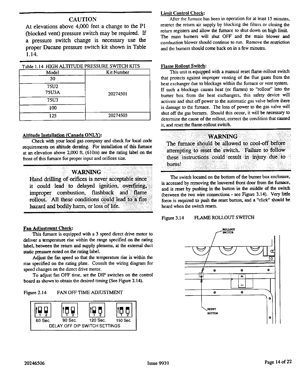
Flame Rollout Switch:
This unit is equipped with a manual reset fiame-rollout switch
that protects against improper venting of the flue gases from the
heat exchanger due to blockage within the furnace or vent system.
If such a blockage causes heat (or flames) to "rollout" into the
burner box from the heat exchangers, this safety device will
activate and shut off power to the automatic gas valve before there
is damage to the furnace. The loss of power to the gas valve will
shut off the gas burners. Should this occur, it will be necessary to
determine the cause of the rollout, correct the condition that caused
it, and reset the flame-rollout switch.
WARNING
Hand drilling of orifices is never acceptable since
it could lead to delayed ignition, overfLring,
improper combustion, flashback and, flame
roUout. All these conditions could leadto a fire
hazard and bodily harm, or loss of life.
Fan Adiustment Check:
This furnace is equipped with a 3 speed direct drive motor to
deliver a temperature rise within the range specified on the rating
label, between the return and supply plenums, at the external duct
static pressure noted on the rating label.
Adjust the fan speed so that the temperature rise is within the
rise specified on the rating plate. Consult the wiring diagram for
speed changes on the direct drive motor.
To adjust fan OFF time, set the DIP switches on the control
board as shown to obtain the desired timing (See Figure 2.14).
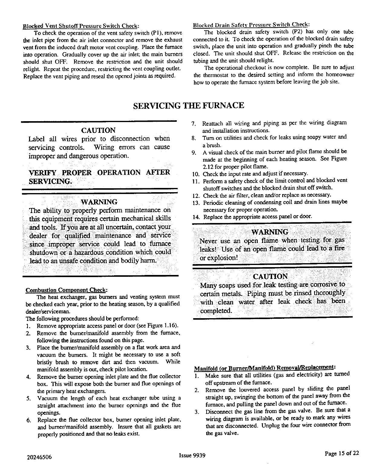
Figure 2.14 FAN OFF TIME ADJUSTMENT
00socDELA,oF?0 ,Psw, oT . ,Nd 0
The switch located on the bottom of the burner box enclosure,
is accessed by removing the louvered front door from the furnace,
and is reset by pushing in the button in the middle of the switch
(between the two wire connections - see Figure 3.14). Very little
force is required to push the reset button, and a "click" should be
heard when the switch resets.
Figure 3.14 FLAME ROLLOUT SWITCH
I_L.LOOT
/
OOO
z i"_7"i i
o o
_SET
20246506 Issue 9939 Page 14 of 22
Blocked Vent ShutoffPressure Switch Check:
To check the operation of the vent safety switch (PI), remove
the inlet pipe from the air inlet connector and remove the exhaust
vent from the induced draft motor vent coupling. Place the furnace
into operation. Gradually cover up the air inlet; the main burners
should shut OFF. Remove the restriction and the unit should
relight. Repeat the procedure, restricting the vent coupling outlet.
Replace the vent piping and reseal the opened joints as required.
Blocked Drain Safety Pressure Switch Check:
The blocked drain safety switch (P2) has only one tube
connected to it. To check the operation of the blocked drain safety
switch, place the unit into operation and gradually pinch the tube
closed. The unit should shut OFF. Release the restriction on the
tubing and the unit should retight.
The operational checkout is now complete. Be sure to adjust
the thermostat to the desired setting and inform the homeowner
how to operate the furnace system before leaving the job site.
SERVICING THE FURNACE
CAUTION
Label all wires prior to disconnection when
servicing controls, Wiring errors can cause
improper and dangerous operation.
VER!FY PROPER OPERATION AFTER
SERVICING.
WARNING
The ability to properly perform maintenance on
this equipment requires certain mechanical skills
and tools. If you are at all uncertain, contact your
dealer for qualified m_ntenance and service
since improper service Could lead to furnace
shutdown or a hazardOUs condition which could
lead to an unsafe condition and bodily harm.
7. Reattach all wiring and piping as per the wiring diagram
and installation insmactions.
8. Turn on utilities and check for leaks using soapy water and
a brush.
9. A visual check of the main burner and pilot flame should be
made at the beginning of each heating season. See Figure
2.12 for proper pilot flame.
10. Check the input rate and adjust if necessary.
11. Perform a safety check of the limit control and blocked vent
shutoff switches and the blocked drain shut off switch.
12. Check the air filter, clean and/or replace as necessary.
13. Periodic cleaning of condensing coil and drain lines maybe
necessary for proper operation.
14. Replace the appropriate access panel or door.
Ne_er use an 6pen flame _hen _fing for g_
ie_i Userf _opea fl_e _oU!d [eadt6
:or explosi0n! :: :::
certain metalS. Pipinl_
with :clean water after leak
Combustion Component Check:
The heat exchanger, gas burners and venting system must
be checked each year, prior to the heating season, by a qualified
dealer/serviceman.
The following procedures should be performed:
1. Remove appropriate access panel or door (see Figure 1.16).
2. Remove the burner/manifold assembly from the furnace,
following the instructions found on this page.
3. Place the burner/manifold assembly on a flat work area and
vacuum the burners. It might be necessary to use a soft
bristly brush to remove dirt and then vacuum. While
manifold assembly is out, check pilot location.
4. Remove the burner opening inlet plate and the flue collector
box. This will expose both the burner and flue openings of
the primary heat exchangers.
5. Vacuum the length of each heat exchanger tube using a
straight attachment into the burner openings and the flue
openings.
6. Replace the flue collector box, burner opening inlet plate,
and burner/manifold assembly. Insure that all gaskets are
properly positioned and that no leaks exist.
Manifold (or Burner/Manifold) Removal/Replacement:
1. Make sure that all utilities (gas and electricity) are turned
off upstream of the furnace.
2. Remove the louvered access panel by sliding the panel
straight up, swinging the bottom of the panel away from the
furnace, and pulling the panel down and out of the furnace.
3. Disconnect the gas line from the gas valve. Be sure that a
wiring diagram is available, or be ready to mark any wires
that are disconnected. Unplug the four wire connector from
the gas valve.
20246506 Issue 9939 Page 15 of 22
Figure1.16 FURNACEPANELREMOVAL
m
4. Remove the burner access panel by removing the seven (7)
No. 10 sheet metal screws that secure the panel to the
cabinet. Be careful not to damage the rubber seal strips that
are attached to the cabinet (behind the access panel).
5. Remove the No. 10 sheet metal screws that secure the
manifold seal plate and gasket to the bottom of the burner
box. The plate and gasket are assembled onto the manifold
pipe and will not come completely loose, but will slide
down the manifold pipe in order to provide clearance for
manifold removal.
6. Remove manifold or boruerimanifold assembly.
Manifold ONLY
a. Remove the two screws that mount the pilot assembly
to the burner bracket.
b. Remove the No. 10 screws that secure the manifold
pipe to both legs of the manifold assembly. The
manifold pipe must be supported during this step,
or it could fall and damage the furnace or cause
bodily injury!
e. Slide the manifold pipe (with valve and orifice)
forward, out of the furnace, being careful not to
damage the pilot assembly.
Burner/Manifold Assembly
a. Remove the No. 10 screws that secure the
burner/manifold assembly legs to the furnace. The
manifold pipe must be supported during this step,
or it could fall and damage the furnace or cause
bodily injury!
b. Slide the burner/manifold assembly forward, out of the
furnace, until the assembly is clear of the manifold
retention pins.
c. Rotate the assembly slightly, in order for the legs to
clear the sides of the cabinet, and remove through the
front of the furnace.
7. To reinstall the manifold pipe or burner/manifold assembly,
reverse the above steps. When replacing the manifold seal
plate to the bottom of the burner box, be sure the gasket is
not tom so a proper seal is achieved. Also insure that the
sealing strips for the burner access door are in position and
undamaged, in order to prevent air leaks around the door.
Blower Removal/Replacement:
I. Turn OFF all electrical power to the furnace.
2. Remove the control box access panel and blower door.
3. Unplug the six-pin plug from the blower control board and
the six pin plug from the blower motor to the control box.
4. Remove the four screws securing the control box in the unit
(two in the cabinet at the sides of the blower door opening
and two at the top rear of the control box). Be sure to
support the control box so that it does not fail!
5. Rotate the control box out of the cabinet and support it so
that no strain is placed on any wiring. It may be necessary
to disconnect the electrical supply and thermostat wiring
from the control board.
6. Remove the blower retaining screws from the front of each
blower leg (See Figure 2.16). These are the two black
screws located in the blower compartment that secure the
blower legs to the blower partition panel.
7. Slide the blower forward about two inches. This wil!
disengage the rear of the blower legs from the blower
partition. Rotate the front of the blower down to clear the
control box moundng tabs on the underside of the blower
partition, and continue sliding the blower forward until it is
out of the unit. Take care to clear the control box mounting
tabs. If necessary, disconnect the auxifiary limit leads on
the side of the blower housing.
R_.e_placement
1. Place the blower in the Mower door opening of the unit and
reconnect the auxiliary limit leads.
2. Slide the blower back, into the uniL taking care to clear the
control box mounting tabs.
3. When the blower is about halfway into the cabinet, rotate
the rear of the blower UP so that the rear of the Mower legs
engage the side rails in the blower partition.
4. Continue sliding the blower into the unit until the front of
the blower housing is behind the control box mounting tabs.
Rotate the front of the blower UP until the legs lie fiat
against the bottom of the blower partition, then slide blower
fully into position. The rear of the blower should be against
the stop in the partition and the rear of the blower legs
should be under the partition.
5. Reattach the two blower securing screws, the control box,
any disconnected wiring, the two six pin plugs, the blower
door, and the control box access panel.
Lubricating Motors:
Direct drive motor and blower assemblies are factory
lubricated and normally do not require oiling. If oiling is
required lubrication of the blower motor is to be preformed only
by a qualifiedscrvice agency. If the blower motor on this
furnace is to be replaced it must only be replaced with one of the
motors as listed in Table 1.17.
Figure 2.16 BLOWER REMOVAL AND REPLACEMENT
_RET_NI_
20246506 Issue 9939 Page 16 of 22
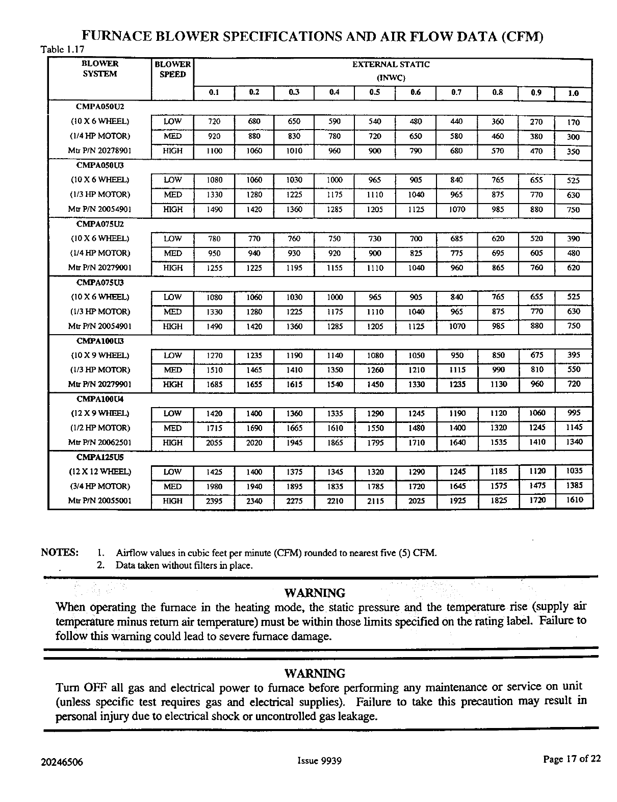
FURNACE BLOWER SPECIFICATIONS AND AIR FLOW DATA (CFM)
Table 1.17
BLOWER
SYSTEM
BLOWER EXTERNAL STATIC
SPEED (INWC)
0.1 I0.2 I 0.3 I 0.4 I 0.5 I0.6 I 0.7 [ 0.8 t0.9 I1.0
CMPA050U2
(10 X 6 WHEEL) LOW 720 680 650 590 540 480 440 360 270 170
(1/4 HP MOTOR) IVIED 920 880 830 780 720 650 580 460 380 304)
Mtr PIN 20278901 HIGH 1100 1060 1010 960 900 790 680 570 470 350
CMPA050U3
(10 X6WHEEL) LOW 1080 1060 1030 1000 965 905 840 765 655 525
(1/3 lip MOTOR) IVIED 1330 1280 1225 1175 1110 1040 965 875 770 630
Mtr PtN 20054901 HIGH 14_) 1420 1360 1285 1205 1125 1070 985 880 750
CMPA075U2
(10 X 6 WHEEL) LOW 780 770 760 750 730 700 685 620 520 390
(1/4 lIP MOTOR) IVIED 950 940 930 920 900 825 775 695 605 480
Mtr P/N 20279001 HIGH 1255 1225 1195 1155 1110 1040 960 865 760 620
CM]PA07SU3
(10 X 6 WHEEL) LOW 1080 1060 1030 10G0 965 905 840 765 655 525
(1/3 FIP MOTOR) MED 1330 1280 1225 1175 1110 1040 965 875 770 630
Mtr PIN 20054901 HIGH 1490 1420 1360 1285 1205 I 125 1070 985 880 750
CMPA100U3
(10 X 9 WHEEL) LOW 1270 1235 1190 1140 1080 1050 950 850 675 395
(1/3 HP MOTOR) IVIED 1510 1465 1410 1350 1260 1210 1115 990 810 550
Mtr PIN 20279901 HIGH 1685 1655 1615 1540 1450 1330 1235 1130 960 720
CM]PA100U4
(12 X 9 WHEEL) LOW 1420 1400 1360 1335 1290 1245 1190 1120 1060 995
(1/2 HP MOTOR) IVIED 1715 1690 1665 1610 1550 1480 1400 1320 1245 1145
Mtr PIN 20062501 HIGH 2055 2020 1945 1865 1795 1710 1640 1535 1410 1340
CMPAI25U5
(12 X 12 WHEEL) LOW 1425 1400 1375 1345 1320 1290 1245 1185 1120 1035
(3/4 HP MOTOR) IVIED 1980 1940 1895 1835 1785 1720 1645 1575 !475 1385
Mtr PIN 20055001 HIGH 2395 2340 2275 2210 2115 2025 1925 1825 1720 1610
NOTES: 1. Airflow values in cubic feet per minute (CFM) rounded to nearest five (5) CFM.
2. Data taken without filters in place.
WARNING
When operating the furnace in the heating mode, the Static pressure and the temperature rise (supply air
temperature minus return air temperature) must be within those limits specified on the rating label. Failure to
follow this warning could lead to severe furnace damage.
WARNING
Turn OFF all gas and electrical power to furnace before performing any maintenance or service on unit
(unless specific test requires gas and electrical supplies). Failure to take this precaution may result in
personal injury due to electrical shock or uncontrolled gas leakage.
20246506 Issue 9939 Page 17 of 22
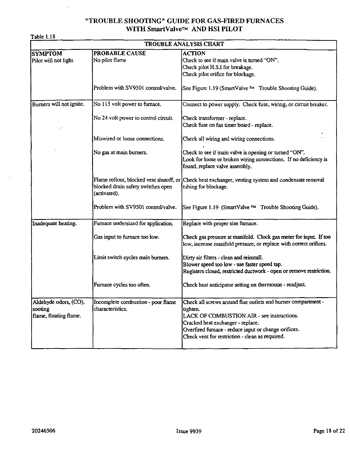
"TROUBLE SHOOTING" GUIDE FOR GAS-FIRED FURNACES
WITH SmartValve TM AND HSI PILOT
Table 1.18
TROUBLE ANALYSIS CHART
SYMPTOM
Pilot will not light.
Burners will not ignite.
inadequate heating.
_ddehyde odors, (CO),
_oofing
flame, floating flame.
PROBABLE CAUSE
No pilot flame
Problem with SV9501 control/valve.
No 115 volt power to fumace.
No 24 volt power to control circuit.
Miswired or loose connections.
No gas at main burners.
Flame rollout, blocked vent shutoff, or
blocked drain safety switches open
(activated).
Problemwith SV9501 control/valve.
Furnace undersized for application.
_qasinput to furnace too low.
Limit switch cycles main burners.
Furnace cycles too often.
[ncomplete combustion - poor flame
haracteristics.
ACTION
Check to see if main valve is turned "ON''.
Check pilot H,S.I for breakage.
Check pilot orifice for blockage.
See Figure 1.19 (SmartValve ru Trouble Shooting Guide).
Connect to power supply. Check fuse, wiring, or circuit breaker.
Check transformer - replace.
Check fuse on fan timer board - replace.
Check all wiring and wiring connections.
Check to see if main valve is opening or turned "ON".
Look for loose or broken wiring connections. If no deficiency is
found, replace valve assembly.
Check heat exchanger, venting system and condensate removal
tubing for blockage.
See Figure 1.19 (SmartValve ra Trouble Shooting Guide).
Replace with proper size furnace.
Check gas pressureat manifold. Clock gas meter for input. If too
low, increase manifold pressure, or replace with correct orifices.
Dirty air filters -clean and reinstall.
Blower speed too low - use faster speed tap.
Registers closed, restricted ductwork - open or remove restriction.
Check heat anticipator setting on thermostat - readjust.
Check all screws around flue outlets and burner compartment-
tighten.
LACK OF COMBUSTION AIR - see instructions.
Cracked heat exchanger - replace.
Overtired furnace - reduce input or change orifices.
Check vent for restriction - clean as required.
20246506 Issue 9939 Page 18 of 22
©
©
=
c_
[.,c_
.<
Z
SmlmValw TM SYSTEM TROUBLESIIOO1]tIG SEOUENCE
NOTE: B_ TROUBLESHOOTING, BECOME F_
START WITH 1HE STAITI'Up AND CHECKOUT PROCEDURF.
i,
_y_ ' I AJ_ILOV_R SY$TEId
Jy_
R_C_ IGNrrlE_ RUG_S.MI_¥
I,.... ÷
I REC;O_.Ci"RLOIrBL_W_r_C4ILi
I NVOLT I/_SETA T:_4DVIk_OFI
e_TC_ _4V, CT_
|4 "e_.T
ji_-°_°"- I
MA,;4yALV_OPL=NS_V4)
kINN_R UG_$ GO_ G_rMcY Vdl_lPLOTBk_*_£R
• i_ F_THCFTHE,_OVEAF_G(XX_
i I ÷i
ST_r
Gn_VeJvemSYSTEM
SEQUENCEOFOPERA110X
E
!r
(]GAY ,
l'I
0
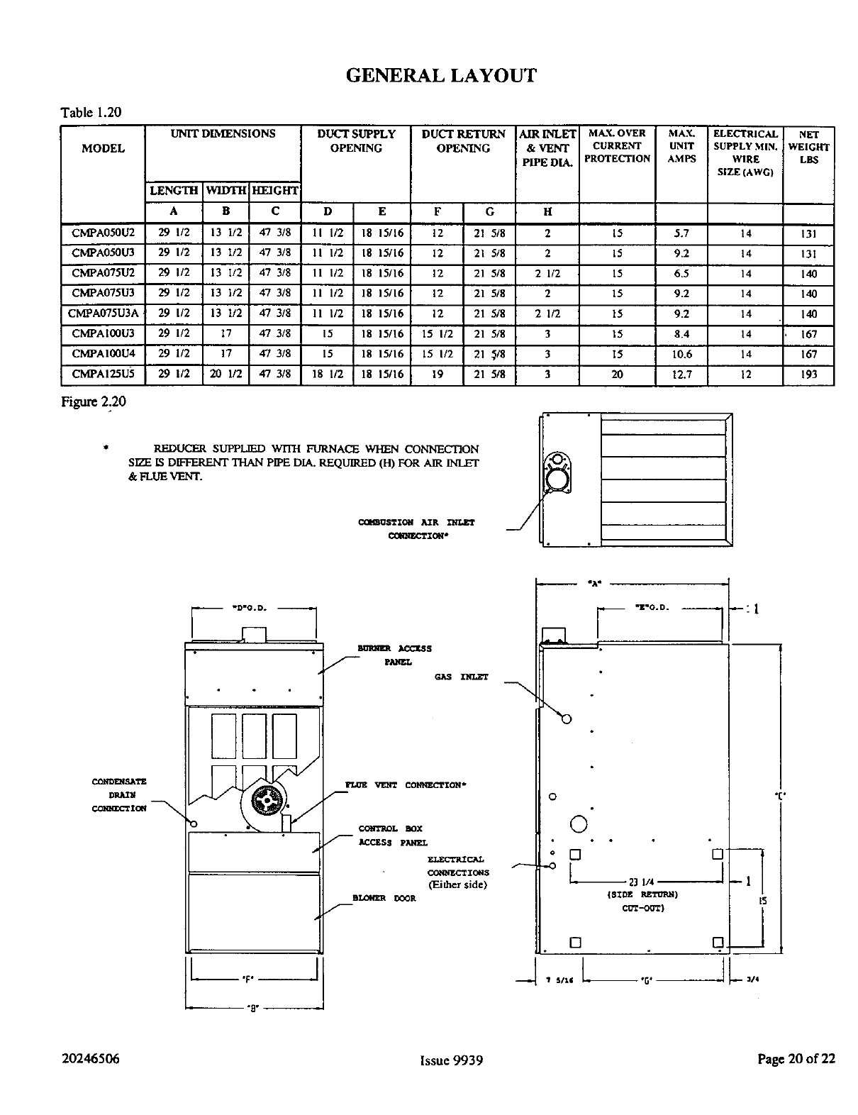
GENERAL LAYOUT
Table 1.20
MODEL
CMPA050U2
CMPA050U3
CMPA075U2
CMPA075U3
CMPA075U3A
CMPA100U3
CMPAI00U4
CMPAI25U5
Figure 2.20
UNIT DIbEENSIONS
LENGTH WIDTH HEIGHT
A B C
29 I/2 13 1/2 47 3/8
29 I/2 13 I/2 47 3/8
29 I/2 13 I/2 47 3/8
29 1/2 13 I/2 47 3/8
29 1/2 13 1/2 47 3/8
29 1/2 17 47 3/8
29 1/2 17 47 3/8
29 1/2 20 1/2 47 3/8
DUCT SUPPLY
OPENING
D E
11 I/2 18 15/16
11 I/2 18 15/16
I1 I/2 18 15/16
11 1/2 18 15/16
11 I/2 18 15/16
15 18 15/16
15 18 15/16
18 1/2 18 15/16
DUCT RETURN
OPENING
AIR INLET
&VENT
PIPEDIA.
MAX. OVER MAX. ELECTRICAL NET
CURRE_rl " UNIT SUPPLY MIN. WEIGHT
PROTECTION AMPS WIRE LBS
SIZE (AWG)
F G
12 21 5/8
12 21 5/8
12 21 5/8
12 21 5/8
12 21 5/8
15 I/2 21 5/8
15 I/2 21 3/8
19 21 5/8
H
2
2
2 1/2
2
2 1/2
3
3
3
15 5.7 14 131
15 9.2 14 131
15 6.5 14 140
15 9.2 14 140
15 9.2 14 140
15 8.4 14 167
15 10.6 14 167
20 12.7 12 193
REDUCER SUPPLIED WITH FURNACE WHEN CONNECTION
SIZE IS D_FFERENT THAN PIPE DIA. REQUIRED (HI FOR AIR INLET
& FLUE VENT.
C_',BOSTZOtl _R
C_RRECTZ_ _/
Ct3h*DI_I.?_,Tg
_s
GAS
_CO)_ZCI'ZON *
m
CO_P_'BOL BOX
ACCESS PAkFEL
F.,LECrP_C_L
COtqNECT IO_IS
(Either side)
IILOW/_ IX_R
male
F--.-oo
o
©
* []
--o [
[]
?s/%6
--:l
23 I/4 _
{SIDE _T_R_g )I_
_--ooT)
I
O..____J
JL
"1:"
20246506 Issue 9939 Page 20 of 22
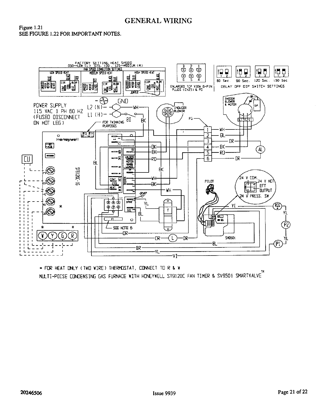
GENERAL WIRING
Figure 1.21
SEE FIGURE 1.22 FOR IMPORTANT NOTES.
YL
YL
,,F[_ HEAT []I__Y(IWO WIRE) TF_-R_TAT, CONNECT TO R&W
MULTI-P01SEF-DNDENSINGGAS FURNAFFWIIH HONEYWELLsTg]20C FAN TIMER & SVg501 SM_J_TVALVE
20246506 Issue 9939 Page 21 of 22
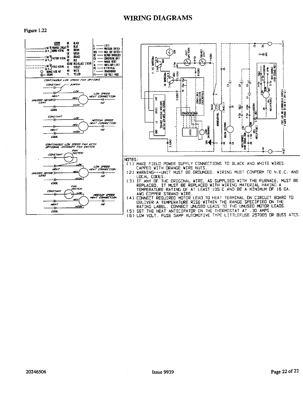
WIRING DIAGRAMS
Figure 1.22
L_Be 8( &_
@ _
--tl_E ¥ F
-'"'"2V22-'_:_ vl VI&e'T
L --- L_[T
_S -- I_LLILffSvIt04,
CI_G'TA,VF
_A+V
Z_AO A_
F_,!
F--_.............T-----_'r_--_
, I
-_ ,s_ _ _ /i_/ / / L _T'S_ _
rE i ':
,, I i ! -, - _ _
NOTES:
(I) MAKE FIELD POWER SUPPLY CONNECTIONS TO BLACK AND WHITE WIRES
CAPPEO WITH ORANGE WIRE NUTS.
(2) WARNING---UNIT MUST BE GROUNDED. WIRING MUST CONFORM TO N.E,C. AND
LOCAL EOOES.
(3) IF ANY OF THE ORIGINAL WIRE, AS SUPPLIED WITH THE FURNACE, MUST BE
REPLACEO, IT MUST 8E REPLACED WITH WIRING MATERIAL HAVING A
TEMPERATURE RATING OF AT LEAST 105 C AND BE AMINIMUM OF 15 GA.
AWG COPPER STRAND WIRE,
(4) CONNECT REOUIREO MOTOR LEAD TO HEAT TERMINAL ON CIRCUIT BOARD TO
OELIVER A TEMPERATURE RISE WITHIN THE RANGE SPECIFIEO ON THE
RATING LABEL, CONNECT UNUSEO LEADS TO THE UNUSEO MOTOR LEADS.
(5) SET THE HEAT ANTICIPATOR ON THE THERMOSTAT AT .30 AMPS,
(6) L0W VOLT. FUSE 5AMP AUTOMOTIVE TYPE LITTLEFUSE 257005 OR BUSS ATE5.
20246506 Issue 9939 Page 22 of 22
