DUNE HD KTTV301W IEEE 802.11b/g/n WiFi Module User Manual GWF 3M05 V15
DUNE HD LTD IEEE 802.11b/g/n WiFi Module GWF 3M05 V15
DUNE HD >
Contents
- 1. Manual 1 of 2
- 2. Manual 2 of 2
Manual 1 of 2

IEEE 802.11 b/g/n WiFi Module
Product Specifications
Model: GWF-3M05
Version: 1.5
2010-1-7
1 of 9
1. Introduction
GWF-3M05 is a WLAN module supporting IEEE 802.11 b/g/n standards with 6-pin connector
supporting USB 2.0 interface. This is a low cost compact WLAN module designed in products
with embedded system for the wireless connectivity. This Module is designed to operate in
2.4GHz ISM frequency band, it applies a highly integrated MAC/BBP and RF single chip RT3070
with 150Mbps PHY rate supporting. It fully complies with IEEE802.11n draft 3.0 and
IEEE802.11b/g feature.
1.2 Features
_ 802.11b: 1, 2, 5.5, 11Mbps;
_ 802.11g: 6, 9, 12, 18,24, 36, 48, 54Mbps
_ 802.11n: (20MHz) MCS0-7, Support up to 72Mbps
_ OFDM, Peak rate 150Mbps, Peak throughput 90Mbps.
_ Security support for 64/128 WEP, WPA, WPA2, TKIP, AES
2. Product Information
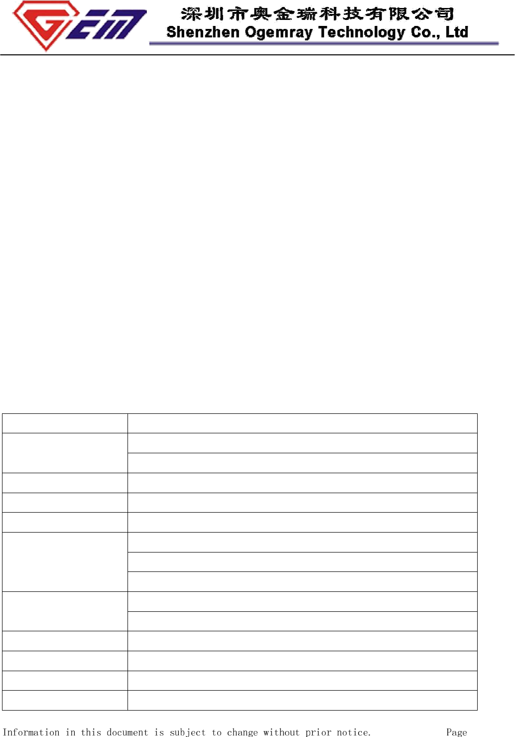
2.1 Specification Overview
Standards IEEE802.11b/g & 802.11n (1T1R mode)
Operating
Frequency
USA (FCC): 2.412GHz ~ 2.462GHz (channel 1 – 11) ISM band
Europe (CE): 2.412GHz ~ 2.472GHz (channel 1 – 13) ISM band
Protocols 802.11b: CCK, QPSK, BPSK, 802.11g/n: OFDM
Antenna External 50 ohm antenna via an I-PEX receptacle
Security WPA/WP2, 64/128/152-bit WEP, WPS
Transmit Output
Power (Typical)
11b: 19±1.0dBm @ 11Mbps
11g: 16±1dBm @ 54Mbps
802.11n: (HT20), 15+/-1dBm,
Receive Sensitivity
(Typical)
11b: -84dBm @ 11Mbps; 11g: -70dBm @ 54Mpbs.
802.11n: (HT20), -66dBm@MSC7
Operating Voltage 5.0VDC ± 5% (or3.3VDV± 5% upon special requirement)
Operating Current <110mA at 5.0V DC input.
Bus Interface USB 2.0/USB1.1
USB Interface 6-pin, 2.0mm pitch male jumper , or 1.0mm pitch connector
2 of 9
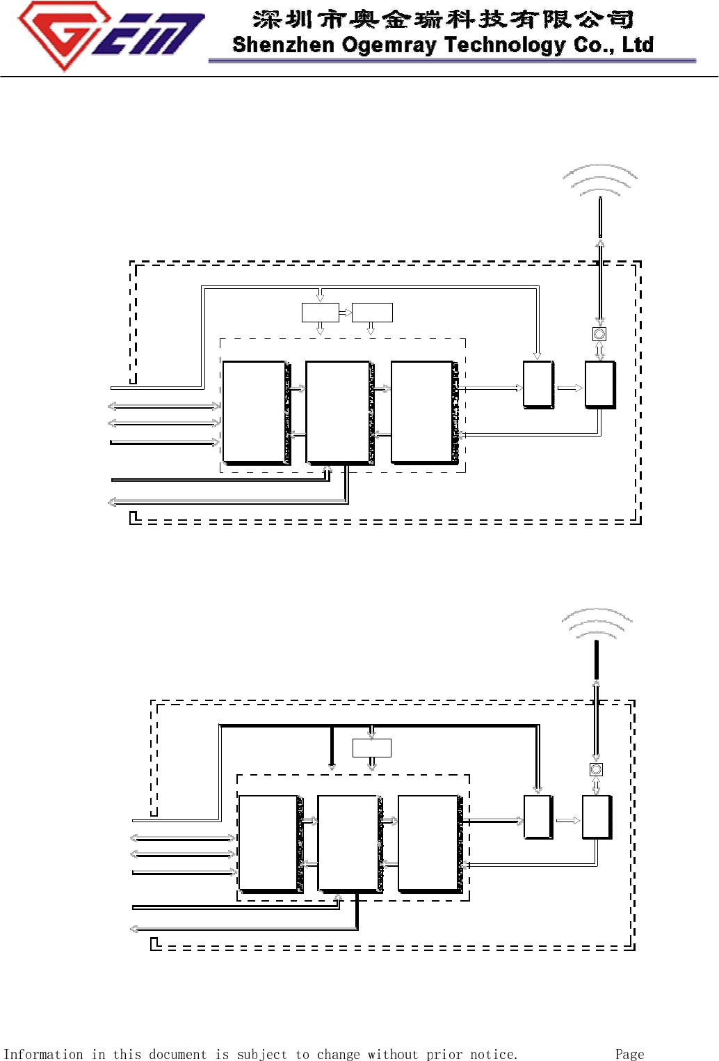
2.2 Hardware Information
2.2.1 Block Diagram
5V/3.3V
External antenna
2.412~2.4835GHz
3.3V/1.8V
I-PEX
Receptacle
USB
Connector
VCC (5V)
DATA+
DATA-
GND
USB
Interface
RT3070
Baseband
MAC/
Packet
Buffer/
Encrption
Engine
RF
Transmitter
RF
Receiver
PA RF
SW
TX CONTROL
EXTERNAL LED
USB WiFi adapter
Figure 1: System Block Diagram of GWF-3M05 5.0V WLAN Module
External antenna
2.412~2.4835GHz
3.3V/1.8V
I-PEX
Receptacle
USB
Connector
VCC(3.3V)
DATA+
DATA-
GND
USB
Interface
RT3070
Baseband
MAC/
Packet
Buffer/
Encrption
Engine
RF
Transmitter
RF
Receiver
PA RF
SW
TX CONTROL
EXTERNAL LED
USB WiFi adapter
Figure 2: System Block Diagram of GWF-3M05 3.3V WLAN Module
3 of 9
2.3 Software and system Information
Operation System CPU Supplier Driver
Linux 2.4/2.6 ARM, MIPSII Available
Windows 2000/XP/Vista X86 Platform Available
Windows CE 5.0/6.0 ARM, MIPSII Available
Mac OS X
10.3/10.4/10.5/10.6 N/A Available
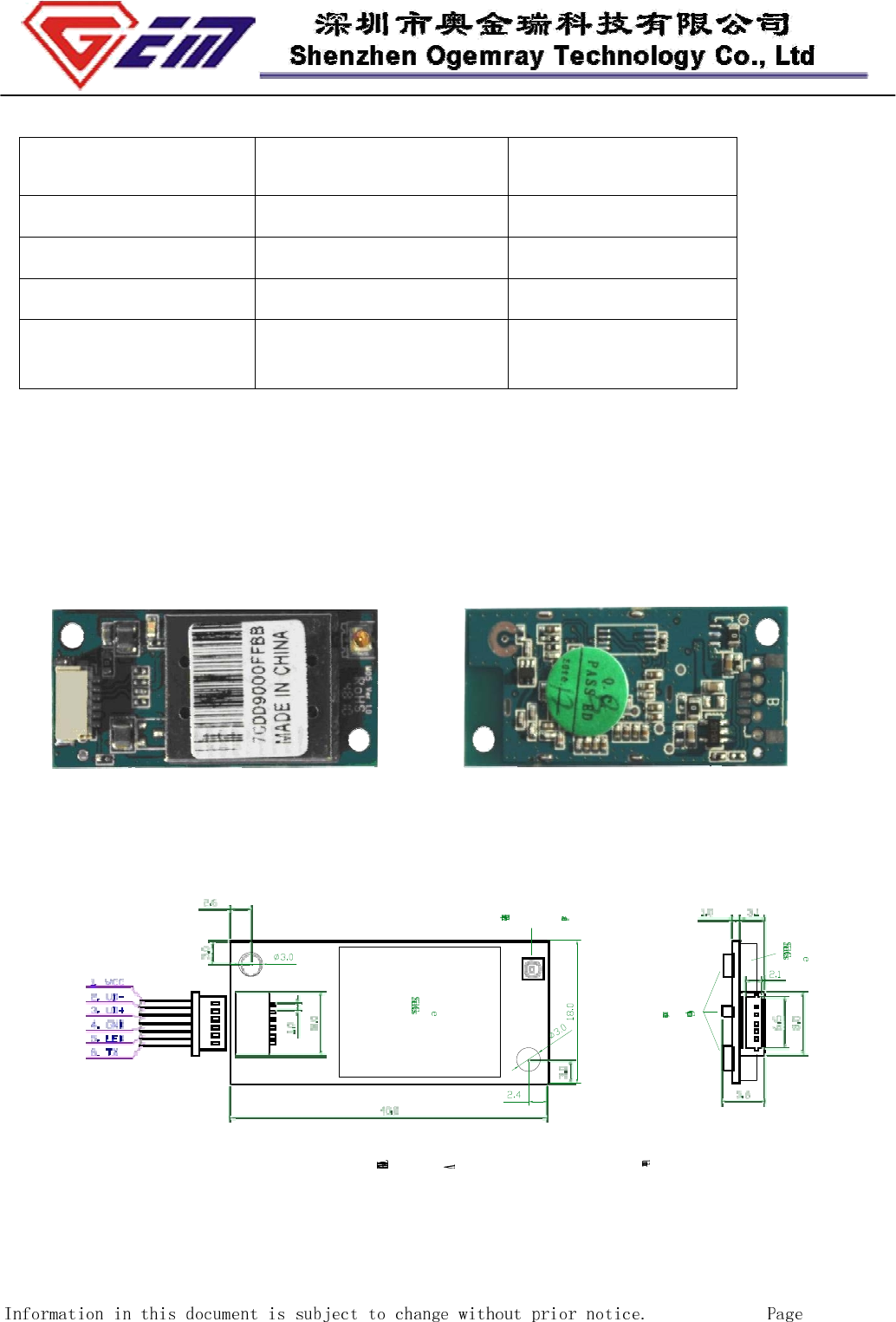
2.4 Mechanical Information
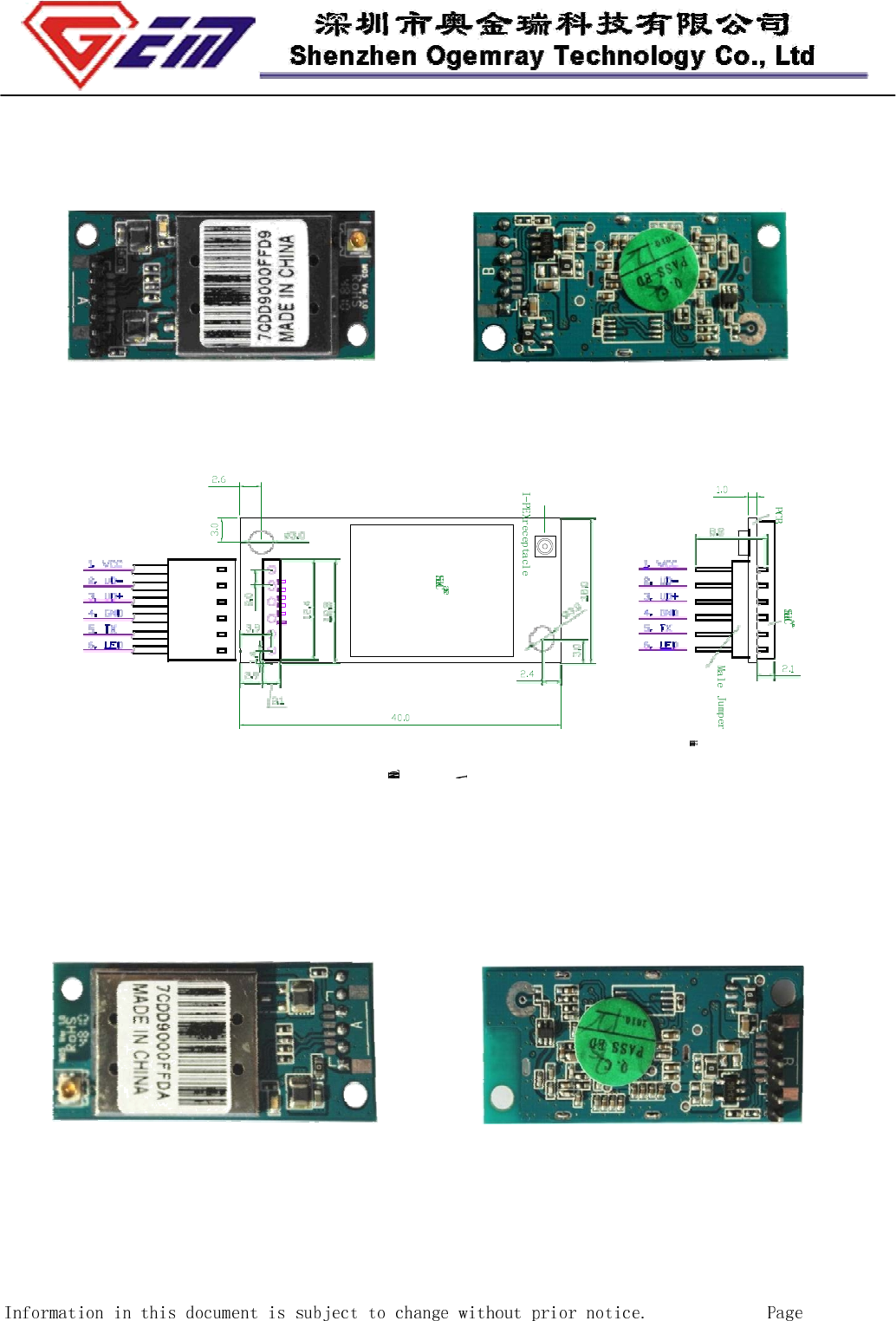
2.4.1 OUTLINE and Connection Interface (Pictures are for reference only)
a). 6-pin 1.0 mm pitch connector.
Model: GWF-3M05-50-CT; GWF-3M05-33-CT
4 of 9
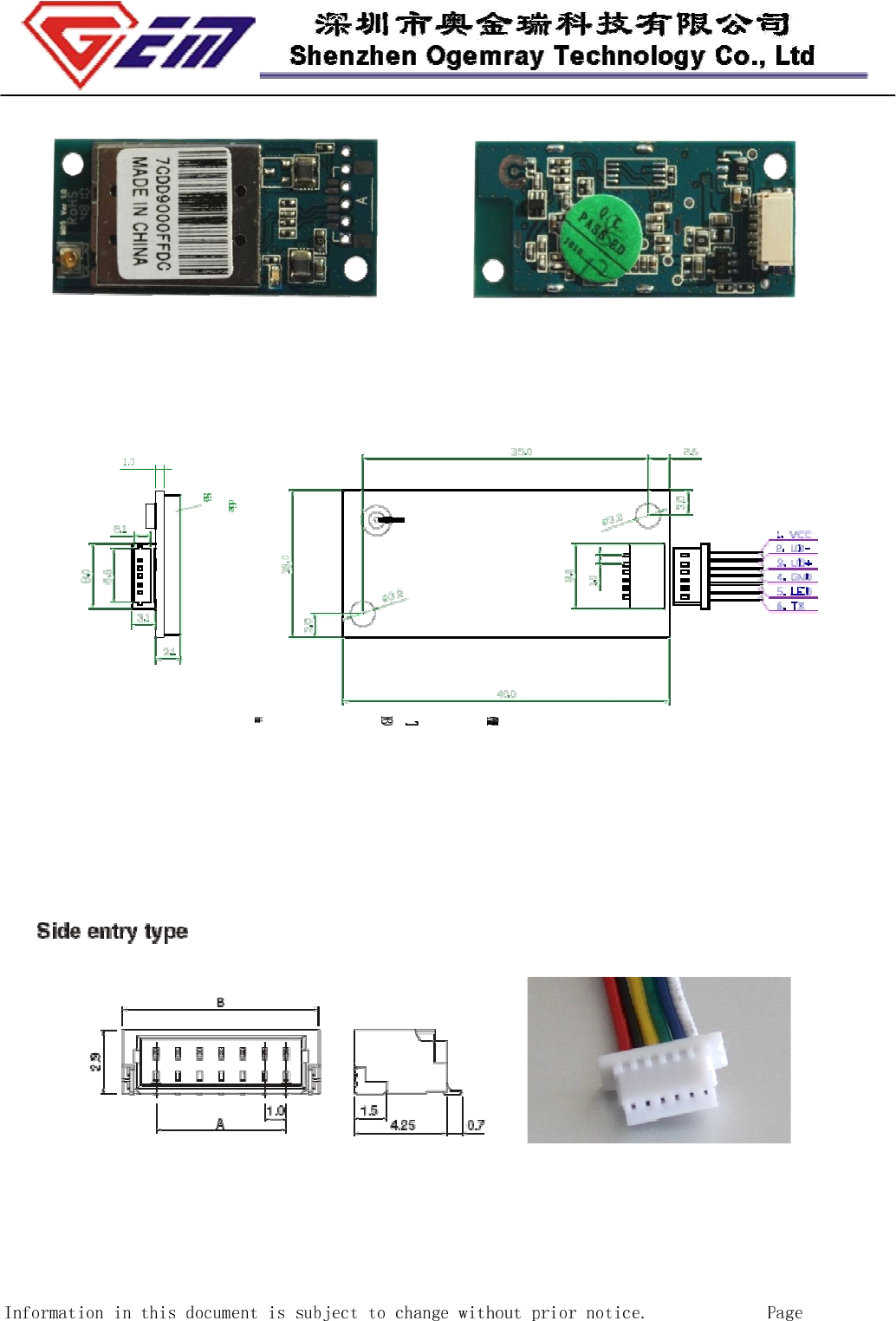
Model: GWF-3M05-50-CB; GWF-3M05-33-CB
Connector information:
The profile of the 6-pin connector
5 of 9
b). 6-pin 2.0 mm pitch male jumper.
Model: GWF-3M05-50-T; GWF-3M05-33-T
Model: GWF-3M05-50-B; GWF-3M05-33-B
6 of 9
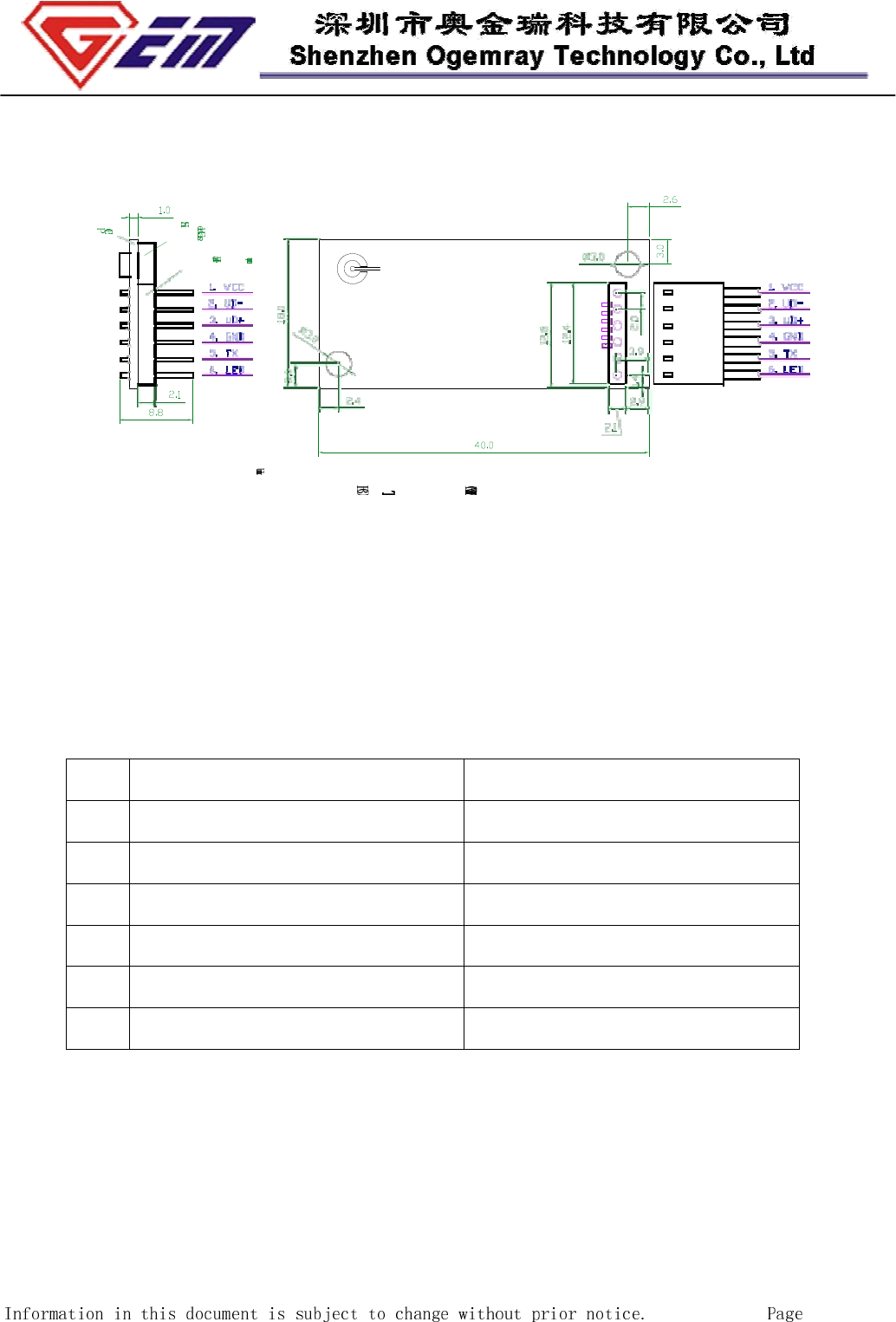
(To be noted: For special application, the direction of the male jumper can be upside
down mounted, or the connector can be 90 degree bended)
2.4.2 Pin definition:
Pin
6-pin 1.0mm pitch connector 6-pin 2.0mm pitch male jumper
1 VCC (3.3 VDC or 5.0VDC) VCC (3.3 VDC or 5.0VDC)
2 UD- ( USB data-) UD- ( USB data-)
3 UD+ (USB data+) UD+ (USB data+)
4 GND (Ground) GND (Ground)
5 LED (Wireless TX status) TX (RF ON/OFF control)
6 TX (RF ON/OFF control) LED (Wireless TX status)
*The TX ( RF ON/OFF control) is low level activated to OFF.
2.4.3 Antenna Connection Information
A 50 ohm external antenna via an I-PEX receptacle. ( Part No: 20279-001E-01)
7 of 9
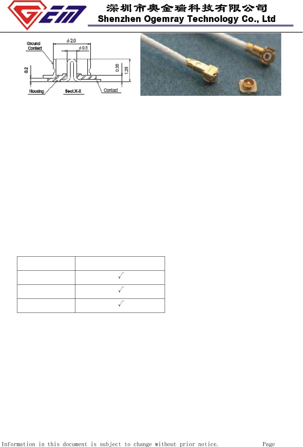
The profile of the I-PEX connector
2.5 Order information:
GWF-3M05-33-T, for 3.3+/-5%VDC, the long pins are at the same side with the shield case.
GWF-3M05-33-B, for 3.3+/-5%VDC, the long pins are at the opposite side with the shield case.
GWF-3M05-50-T, for 5.0+/-5%VDC, the long pins are at the same side with the shield case.
GWF-3M05-50-B, for 5.0+/-5%VDC, the long pins are at the opposite side with the shield case.
GWF-3M05-50-CT, for 5.0+/-5%VDC, Soldered with 6 pin connector, top side mounted.
GWF-3M05-50-CB, for 5.0+/-5%VDC, Soldered with 6 pin connector, bottom side mounted.
GWF-3M05-33-CT, for 3.3+/-5%VDC, Soldered with 6 pin connector, top side mounted.
GWF-3M05-33-CB, for 3.3+/-5%VDC, Soldered with 6 pin connector, bottom side mounted .
3. Agency Approval
Agency Approval
FCC Part15
CE
RoHS
4. Environment
4.1 Temperature
4.1.1 Operating Temperature
Continuous reliable operation in ambient temperature: 0ºC to +50ºC.
4.1.2 Storage Temperature
The product is not damaged or degraded when keeping in -20ºC to +85ºC.
4.2 Humidity
4.2.1 Operating Humidity Conditions
8 of 9

The product is capable of continuous reliable operation when subjected to relative humidity in
the range of 20% to 80% (non-condensing).
4.2.2 Non-Operating Humidity Conditions (including warehouse)
The product is not damaged or degraded when kept in the relative humidity range
from 20% to 80%.
5 Disclaimer
THESE MATERIALS AND INFORMATION ARE PROVIDED “AS IS” WITHOUT WARRANTY
OF ANY KIND, EITHER EXPRESS OR IMPLIED , INCLUDING BUT NOT LIMITED TO, THE
IMPLIED WARRANTIES OF MERCHANTABILITY, FITNESS FOR A PARTICULAR PURPOSE
OR NON-INFRINGEMENT.
We uses reasonable efforts to include accurate and up-to-date information on this document; it
does not, however, make any representations as to its accuracy or completeness of the
information, text, graphics, links or other items contained within these materials. Your use of this
Document is at your own risk. Ogemray, its suppliers, and other parties involved in creating and
delivering this Document’s contents shall not be liable for any special, indirect, incidental, or
consequential damages, including without limitation, lost revenues or lost profits.
9 of 9