DUNKIRK Boiler Manual L0611128
User Manual: DUNKIRK DUNKIRK Boiler Manual DUNKIRK Boiler Owner's Manual, DUNKIRK Boiler installation guides
Open the PDF directly: View PDF ![]() .
.
Page Count: 32
Dml' l'rl-
G s-:-ir_:
Steam or
VVater
|OIL|R
INSTALLATION INSTRUCTIONS
These instructions must be affixed on or adjacent to the boiler.
contents
Rules for Safe Installation and Operation .................................................................. 3
Boiler Ratings and Capacities .................................................................................... 4
Boiler Dimensions ...................................................................................................... 5
Combustion Air and Boiler Location ........................................................................... 6
Assembly of Bases ..................................................................................................... 7
Assembly of Sections and Draft Hoods ...................................................................... 7
Connecting Gas Service .......................................................................................... 10
Installing Boiler Jacket ............................................................................................. 11
Boiler Controls .......................................................................................................... 12
Water Boiler Piping .................................................................................................. 13
Steam Boiler Piping .................................................................................................. 15
Flue Connection and Venting ................................................................................... 16
Electrical Wiring ....................................................................................................... 17
Operation and Service ............................................................................................. 21
Checking and Adjusting ........................................................................................... 24
Parts ......................................................................................................................... 26
introduction
Please read our instructions before you install and use your new boiler. This will help
assure you of proper installation and help you avoid needless service.
You may plan to install the boiler yourself. You must then realize that the wrong use
of any tool can be dangerous, unless you know how to use the tool and equipment
and understand the electrical wiring, piping, and potential hazards involved. The
boiler must be installed in accordance with the requirements of the local utility and
those of other authorities.
2
RULES FOR SAFE INSTALLATION
AND OPERATION
1 . Read the Owner's Manual and the Rules for Safe
operation carefully. Failure to follow the rules for safe
operation and the instructions could cause a
malfunction of the boiler and result in death, serious
bodily injury, and/or property damage.
2. Check your local codes and utility requirements before
installation. The installation must be in accordance with
their directives.
.
.
Before servicing, allow boiler to cool and always shut
off any electricity and gas to boiler when working on it.
This will prevent any electrical shocks or burns.
Never test for leaks with an open flame. Use soap suds
to check alt connections. This will avoid any possibility
of fire or explosion.
Be certain boiler is equipped for type of gas (natural)
to be used. Overfiring wilt result in premature failure of
the boiler sections and cause dangerous operation.
Never vent this boiler into an enclosed space. Always
connect the boiler to a chimney and vent to the outside.
Never vent to another room or inside a building.
Be sure there is adequate air supply for complete
combustion.
8. Follow a regular service and maintenance schedule
for efficient and safe operation.
9. Never install the boiler on carpeting.
10. Keep boiler area clear and free from combustible
material such as gasoline and other flammable vapors
and liquids.
WHEN YOUR BOILER ARRIVES
When your boiler arrives be sure to save and refer to the
instructions.
First, inspect each item received for visible damage. If any
parts are damaged, report this to the freight company
immediately and request them to call and make an
inspection before you make any installation. Have the
inspector prepare a signed report. Send a copy of this report
to the manufacturer and we will send replacements for the
damaged parts. But we must have the signed inspection
report of the freight company to prove their liability.
Read these instructions carefully before beginning the
installation to be sure all packages have been received. It
is recommended that you follow the step-by-step
instructions for best assembly results. Before discarding
any packing material carefully examine for loose parts. Also
store all parts received where they wilt not be lost or
damaged.
CODES GOVERNING INSTALLATION
Boiler should be installed in accordance to the latest edition
of American National Standard National Fuel Gas Code
Z223.1 (Available from the American Gas Association, 8501
East Pleasant Valley Road, Cleveland, Ohio 44131).
Reference should also be made to local gas utility
regulations and other codes in effect in the area in which
the installation is to be made. The jurisdiction normally
covers electrical wiring, gas piping, flue specification, and
insulation of adjacent combustible material where required
clearance cannot be maintained.
Where required by the authority having jurisdiction, the
installation must conform to American Society of
Mechanical Engineers Safety Code for Controls and Safety
Devices for Automatically Fired Boilers, No. CSD-1.
INSTALLATION
This boiler is designed to provide wide capacity range with
multiple burner modules, each equipped with its own set of
controls. For purposes of orientation, the manifold side of
the boiler is considered the front. The end sections are so
designed that the controls may be placed on either the left
or right end. These instructions are written for the
assembling of the boiler starting with the left side and
working to the right side. If the boiler is to be used as a
steam boiler and connected to another steam boiler, the
factory designed water lines of the two boilers must be of
equal height above the floor.
A hot water boiler installed above radiation level must be
provided with a low water cutoff device either as a part of
the boiler or at the time of boiler installation.
The boiler and its individual shutoff valve must be
disconnected from the gas supply piping system during
any pressure testing of that system at test pressures in
excess of 1/2 psig (3.5 kPa).
The boiler must be isolated from the gas supply piping
system by closing its individual manual shutoff valve during
any pressure testing of the gas supply piping system at
test pressures equal to or less than 1/2 psig (3.5 kPa)
3
@®
CHART 1
BOILER
MODEL
NO.
JC 300
JC 400
JC 500
JC 600
JC 700
JC 800
JC 900
JC1000
JC1100
JC1200
JC1300
JC1400
JC1500
JC1600
JC1700
JC1800
JC1900
JC2000
JC2100
JC2200
JC2300
JC2400
JC2500
JC2600
JC2700
JC2800
JC2900
JC3000
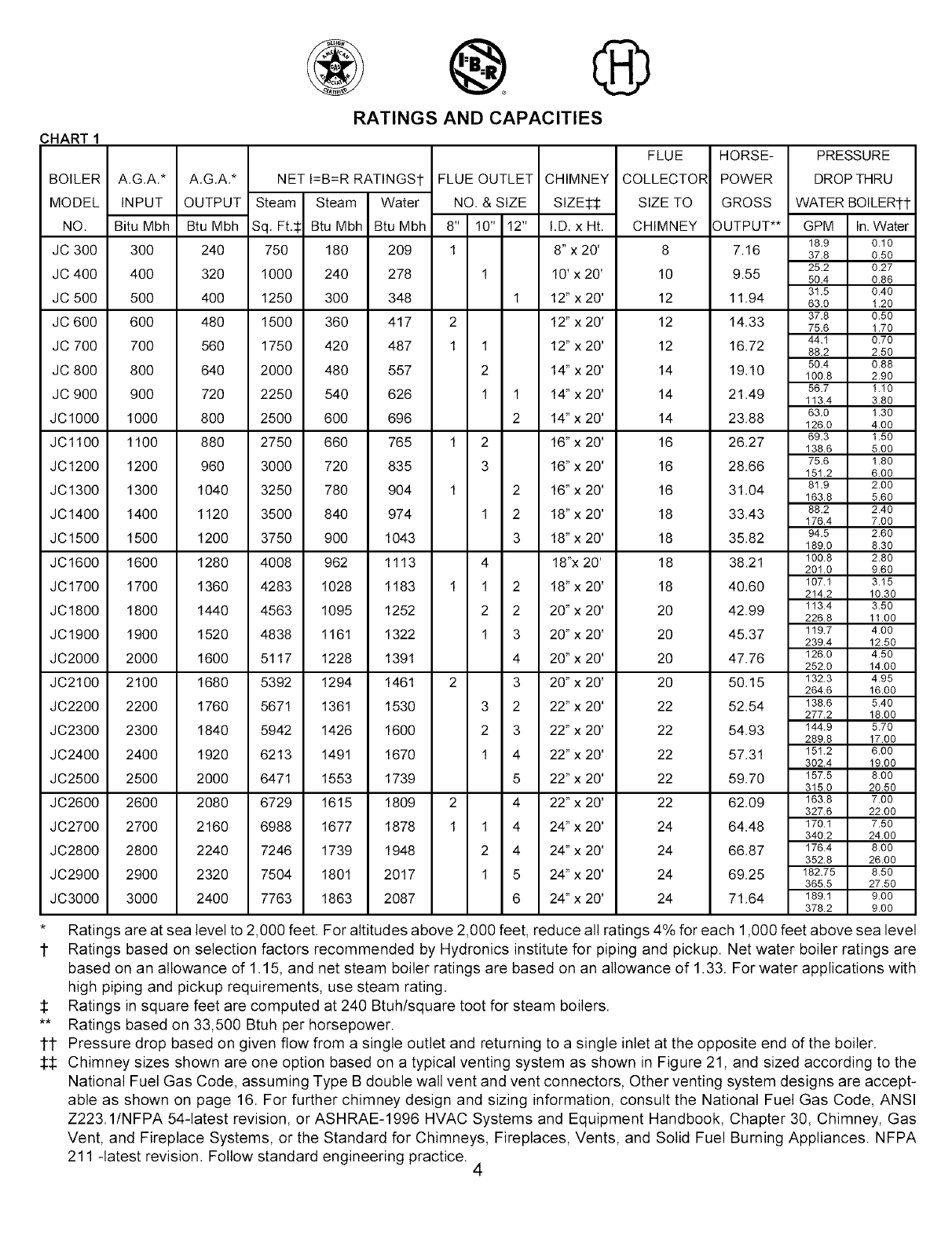
RATINGS AND CAPACITIES
A.G.A.*
INPUT
Bitu Mbh
3O0
400
5O0
600
7O0
8OO
900
1000
1100
1200
1300
1400
1500
1600
1700
1800
1900
2000
2100
2200
2300
2400
2500
2600
2700
2800
2900
3000
A.G.A.* NET I=B=R RATINGSt
OUTPUT Steam Steam Water
Btu Mbh Sq. Ft.$ Btu Mbh Btu Mbh
240 750 180 209
320 1000 240 278
400 1250 300 348
480 1500 360 417
560 1750 420 487
640 2000 480 557
720 2250 540 626
800 2500 600 696
880 2750 660 765
960 3000 720 835
1040 3250 780 904
1120 3500 840 974
1200 3750 900 1043
1280 4008 962 1113
1360 4283 1028 1183
1440 4563 1095 1252
1520 4838 1161 1322
1600 5117 1228 1391
1680 5392 1294 1461
1760 5671 1361 1530
1840 5942 1426 1600
1920 6213 1491 1670
2000 6471 1553 1739
2080 6729 1615 1809
2160 6988 1677 1878
2240 7246 1739 1948
2320 7504 1801 2017
2400 7763 1863 2087
FLUE OUTLET CHIMNEY
NO. & SIZE SIZE$$
8" 10" 12" I.D. x Ht.
1 8"x 20'
1 10'x 20'
1 12" x 20'
2 12" x 20'
1 1 12" x 20'
2 14"x 20'
1 1 14"x 20'
2 14"x 20'
1 2 16"x 20'
3 16"x 20'
1 2 16"x 20'
1 2 18"x 20'
3 18"x 20'
4 18"x 20'
1 1 2 18"x 20'
2 2 20"x 20'
1 3 20"x 20'
4 20"x 20'
2 3 20"x 20'
3 2 22"x 20'
2 3 22"x 20'
1 4 22"x 20'
5 22"x 20'
2 4 22"x 20'
1 1 4 24"x 20'
2 4 24"x 20'
1 5 24"x 20'
6 24"x 20'
FLUE
COLLECTOR
SIZE TO
CHIMNEY
8
10
12
12
12
14
14
14
16
16
16
18
18
18
18
20
20
20
20
22
22
22
22
22
24
24
24
24
HORSE-
POWER
GROSS
OUTPUT**
7.16
9.55
11.94
14.33
16.72
19.10
21.49
23.88
26.27
28.66
31.04
33.43
35.82
38.21
40.60
42.99
45.37
47.76
50.15
52.54
54.93
57.31
59.70
62.09
64.48
66.87
69.25
71.64
PRESSURE
DROP THRU
WATER BOILERI-I-
GPM In.Water
18.9 0.10
37.8 0.50
25.2 0.27
50.4 0.86
31.5 0.40
63.0 1.20
37.8 0.50
75.6 1.70
44.1 0.70
88.2 2.50
50.4 0.88
100.8 2.90
56.7 1.10
113.4 3.80
63.0 1.30
126.0 4.00
69.3 1.50
138.6 5.00
75.6 1.80
151.2 6.00
81.9 2.00
163.8 5.60
88.2 2.40
176.4 7.00
94.5 2.60
189.0 8.30
100.8 2.80
201.0 9.60
187.1 3.15
214.2 10.30
113.4 3.50
226.8 11.00
119.7 4.00
239.4 12.50
126.0 4.50
252.0 14.00
132.3 4.95
264.6 16.00
138.6 5.40
277.2 18.00
144.9 5.70
289.8 17.00
151.2 6.00
302.4 19.00
157.5 8.00
315.0 20.50
163.8 7.00
327.6 22.00
170.1 7.50
340.2 24.00
176.4 8.00
352.8 26.00
182.75 8.50
365.5 27.50
189.1 9.00
378.2 9.00
Ratings are at sea level to 2,000 feet. For altitudes above 2,000 feet, reduce all ratings 4% for each 1,000 feet above sea level
1 Ratings based on selection factors recommended by Hydronics institute for piping and pickup. Net water boiler ratings are
based on an allowance of 1.15, and net steam boiler ratings are based on an allowance of 1.33. For water applications with
high piping and pickup requirements, use steam rating.
1: Ratings in square feet are computed at 240 Btuh/square toot for steam boilers.
** Ratings based on 33,500 Btuh per horsepower.
lt Pressure drop based on given flow from a single outlet and returning to a single inlet at the opposite end of the boiler.
:I::I: Chimney sizes shown are one option based on a typical venting system as shown in Figure 21, and sized according to the
National Fuel Gas Code, assuming Type B double wall vent and vent connectors, Other venting system designs are accept-
able as shown on page 16. For further chimney design and sizing information, consult the National Fuel Gas Code, ANSI
Z223.1/NFPA 54-latest revision, or ASHRAE-1996 HVAC Systems and Equipment Handbook, Chapter 30, Chimney, Gas
Vent, and Fireplace Systems, or the Standard for Chimneys, Fireplaces, Vents, and Solid Fuel Burning Appliances. NFPA
211 -latest revision. Follow standard engineering practice. 4
EZZZ] EZ_ EZB _ _ _-
AA
A
SUPPLY_ --'dATER
38"
89 _
J
LINE
47_" 33.__
; L
_FLFIOR LINE
FRONT VIEW
ICT]_ 7F_ F_G TH7 I_" 1 _FLUE HUTLETS
RETURN _ _ 0 0 _ _ _JJRETURN
SUPPLY SUPPLY
TOP VIEW
Z_............................................
LEFT SIDE VIEW
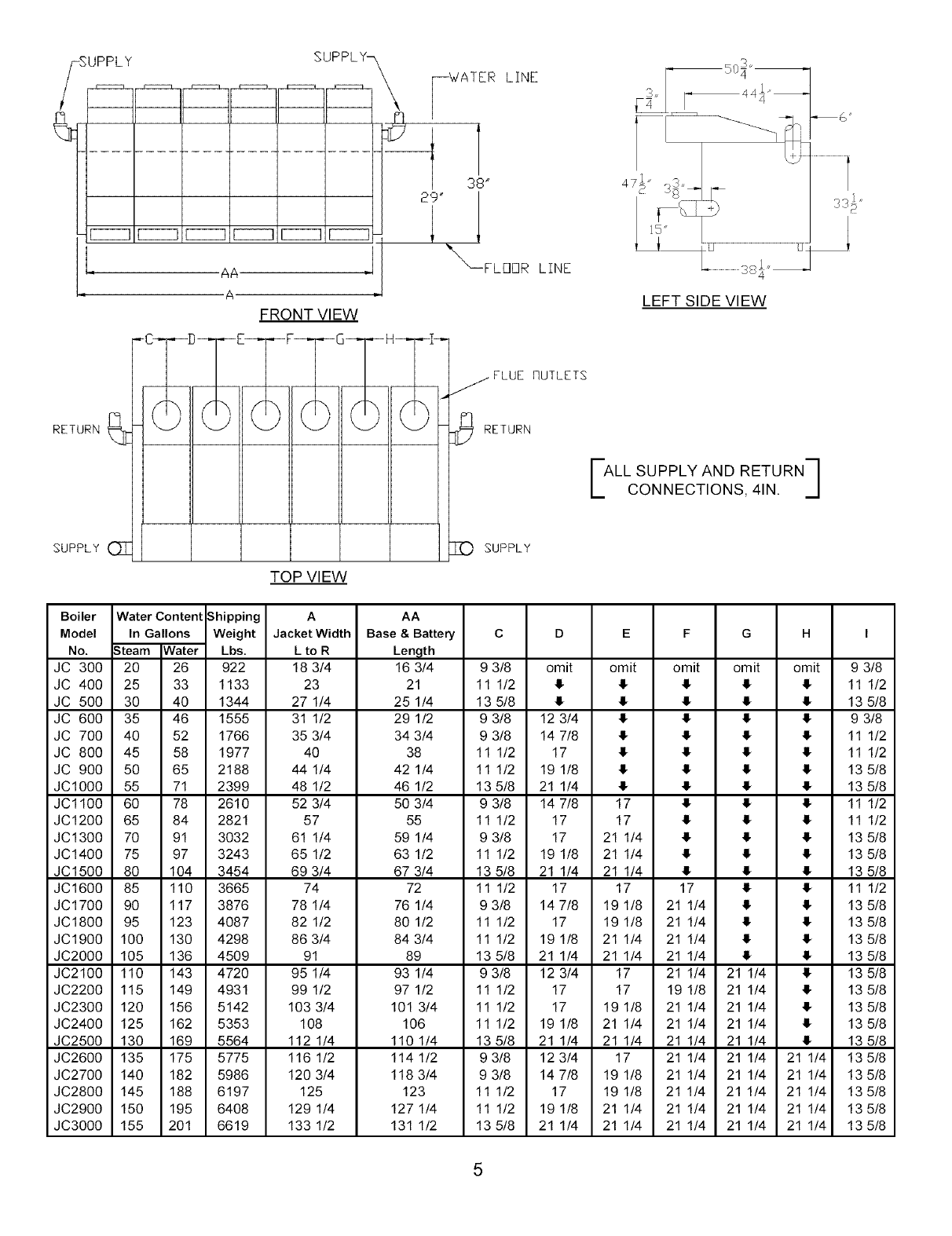
ALL SUPPLY AND RETURN
CONNECTIONS, 4IN. ]
Boiler Water Content Shipping A AA
Model In Gallons Weight Jacket Width Base &Battery CDE F GH I
No. .3team Water Lbs. L to R Length
JC 300 20 26 922 18 3/4 16 3/4 9 3/8 omit omit omit omit omit 9 3/8
JC 400 25 33 1133 23 21 11 1/2 4 4 4 4 4 11 1/2
JC 500 30 40 1344 27 1/4 25 1/4 13 5/8 4 4 4 4 4 13 5/8
JC 600 35 46 1555 31 1/2 29 1/2 9 3/8 12 3/4 4 4 4 4 9 3/8
JC 700 40 52 1766 35 3/4 34 3/4 9 3/8 14 7/8 4 4 4 4 11 1/2
JC 800 45 58 1977 40 38 11 1/2 17 4 4 4 4 11 1/2
JC 900 50 65 2188 44 1/4 42 1/4 11 1/2 19 1/8 4 4 4 4 13 5/8
JC1000 55 71 2399 48 1/2 46 1/2 13 5/8 21 1/4 4 4 4 4 13 5/8
JC1100 60 78 2610 52 3/4 50 3/4 9 3/8 14 7/8 17 4 4 4 11 1/2
JC1200 65 84 2821 57 55 11 1/2 17 17 4 4 4 11 1/2
JC1300 70 91 3032 61 1/4 59 1/4 9 3/8 17 21 1/4 4 4 4 13 5/8
JC1400 75 97 3243 65 1/2 63 1/2 11 1/2 19 1/8 21 1/4 4 4 4 13 5/8
JC1500 80 104 3454 69 3/4 67 3/4 13 5/8 21 1/4 21 1/4 4 4 4 13 5/8
JC1600 85 110 3665 74 72 11 1/2 17 17 17 4 4 11 1/2
JC1700 90 117 3876 78 1/4 76 1/4 9 3/8 14 7/8 19 1/8 21 1/4 4 4 13 5/8
JC1800 95 123 4087 82 1/2 80 1/2 11 1/2 17 19 1/8 21 1/4 4 4 13 5/8
JC1900 100 130 4298 86 3/4 84 3/4 11 1/2 19 1/8 21 1/4 21 1/4 4 4 13 5/8
JC2000 105 136 4509 91 89 13 5/8 21 1/4 21 1/4 21 1/4 4 4 13 5/8
JC2100 110 143 4720 95 1/4 93 1/4 9 3/8 12 3/4 17 21 1/4 21 1/4 413 5/8
JC2200 115 149 4931 99 1/2 97 1/2 11 1/2 17 17 19 1/8 21 1/4 413 5/8
JC2300 120 156 5142 103 3/4 101 3/4 11 1/2 17 19 1/8 21 1/4 21 1/4 413 5/8
JC2400 125 162 5353 108 106 11 1/2 19 1/8 21 1/4 21 1/4 21 1/4 413 5/8
JC2500 130 169 5564 112 1/4 110 1/4 13 5/8 21 1/4 21 1/4 21 1/4 21 1/4 413 5/8
JC2600 135 175 5775 1161/2 1141/2 93/8 123/4 17 21 1/4 21 1/4 21 1/4 135/8
JC2700 140 182 5986 120 3/4 118 3/4 9 3/8 14 7/8 19 1/8 21 1/4 21 1/4 21 1/4 13 5/8
JC2800 145 188 6197 125 123 11 1/2 17 19 1/8 21 1/4 21 1/4 21 1/4 135/8
JC2900 150 195 6408 129 1/4 127 1/4 11 1/2 19 1/8 21 1/4 21 1/4 21 1/4 21 1/4 135/8
JC3000 155 201 6619 133 1/2 131 1/2 13 5/8 21 1/4 21 1/4 21 1/4 21 1/4 21 1/4 13 5/8
5
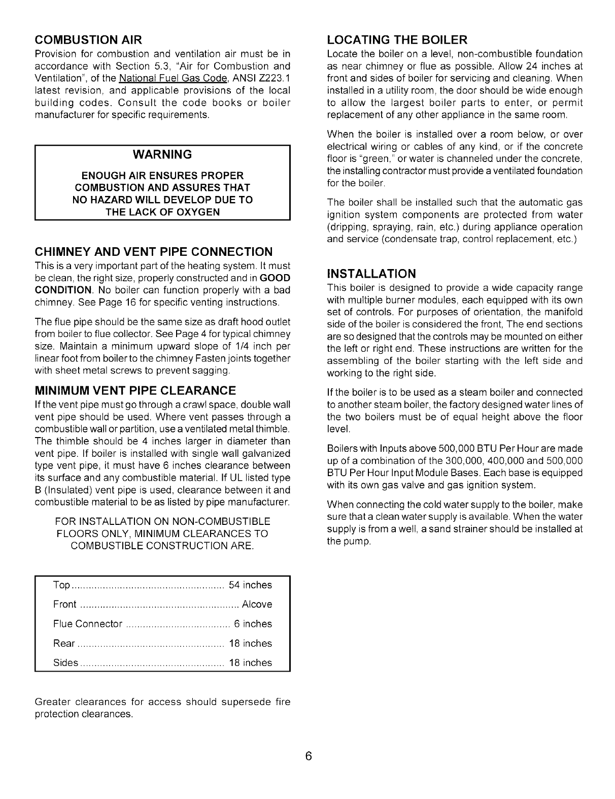
COMBUSTION AIR
Provision for combustion and ventilation air must be in
accordance with Section 5.3, "Air for Combustion and
Ventilation", of the National Fuel Gas Code. ANSI Z223.1
latest revision, and applicable provisions of the local
building codes. Consult the code books or boiler
manufacturer for specific requirements.
WARNING
ENOUGH AIR ENSURES PROPER
COMBUSTION AND ASSURES THAT
NO HAZARD WlLL DEVELOP DUE TO
THELACK OF OXYGEN
CHIMNEY AND VENT PIPE CONNECTION
This is a very important part of the heating system. It must
be clean, the right size, properly constructed and in GOOD
CONDITION. No boiler can function properly with a bad
chimney. See Page 16 for specific venting instructions.
The flue pipe should be the same size as draft hood outlet
from boiler to flue collector. See Page 4 for typical chimney
size. Maintain a minimum upward slope of 1/4 inch per
linear foot from boiler to the chimney Fasten joints together
with sheet metal screws to prevent sagging.
MINIMUM VENT PIPE CLEARANCE
If the vent pipe must go through a crawl space, double walt
vent pipe should be used. Where vent passes through a
combustible walt or partition, use a ventilated metal thimble.
The thimble should be 4 inches larger in diameter than
vent pipe. If boiler is installed with single wall galvanized
type vent pipe, it must have 6 inches clearance between
its surface and any combustible material. If UL listed type
B (Insulated) vent pipe is used, clearance between it and
combustible material to be as listed by pipe manufacturer.
FOR INSTALLATION ON NON-COMBUSTIBLE
FLOORS ONLY, MINIMUM CLEARANCES TO
COMBUSTIBLE CONSTRUCTION ARE.
LOCATING THE BOILER
Locate the boiler on a level, non-combustible foundation
as near chimney or flue as possible. Allow 24 inches at
front and sides of boiler for servicing and cleaning. When
installed in a utility room, the door should be wide enough
to allow the largest boiler parts to enter, or permit
replacement of any other appliance in the same room.
When the boiler is installed over a room below, or over
electrical wiring or cables of any kind, or if the concrete
floor is "green," or water is channeled under the concrete,
the installing contractor must provide a ventilated foundation
for the boiler.
The boiler shall be installed such that the automatic gas
ignition system components are protected from water
(dripping, spraying, rain, etc.) during appliance operation
and service (condensate trap, control replacement, etc.)
INSTALLATION
This boiler is designed to provide a wide capacity range
with multiple burner modules, each equipped with its own
set of controls. For purposes of orientation, the manifold
side of the boiler is considered the front, The end sections
are so designed that the controls may be mounted on either
the left or right end. These instructions are written for the
assembling of the boiler starting with the left side and
working to the right side.
If the boiler is to be used as a steam boiler and connected
to another steam boiler, the factory designed water lines of
the two boilers must be of equal height above the floor
level.
Boilers with Inputs above 500,000 BTU Per Hour are made
up of a combination of the 300,000,400,000 and 500,000
BTU Per Hour Input Module Bases. Each base is equipped
with its own gas valve and gas ignition system.
When connecting the cold water supply to the boiler, make
sure that a clean water supply is available. When the water
supply is from a welt, a sand strainer should be installed at
the pump.
Top ...................................................... 54 inches
Front ........................................................ Alcove
Flue Connector ..................................... 6 inches
Rear .................................................... 18 inches
Sides ................................................... 18 inches
Greater clearances for access should supersede fire
protection clearances.
6
ASSEMBLY OF BASES
The 300, 400 and 500 boilers are the basic models. The
300 model has (6) burners, the 400 model has (8) burners
and the 500 model has (10) burners. Combinations of the
basic models are used to assemble the 600 through 3000
models. See Chart No. 2 for the proper order of assembly
When two or more bases are used to assemble the boiler,
be sure the top angles of the bases are even. (See Figure
No. 6). The bases are fastened together with 5/16 cap
screws and nuts. Insert two screws in the front posts and
two in the rear posts as shown in Figure No. 1. After bases
are fastened together, install the base end panels. These
end panels must be installed before assembling sections.
Important: After bases are assembled check to be sure
they are level.
STARTING SECTION ASSEMBLY
The sections may be started from either the left or right
end of the base. Place the end section on the base with
the parting line of the section directly over the joint of the
base and base end closure. With boilers having two or more
bases, as you progress be sure the parting line (center-line
of section) of the intermediate sections falt on the junction
of the two bases. Install a top cover support bracket on the
draw bolts of the intermediate sections at each base
junction.
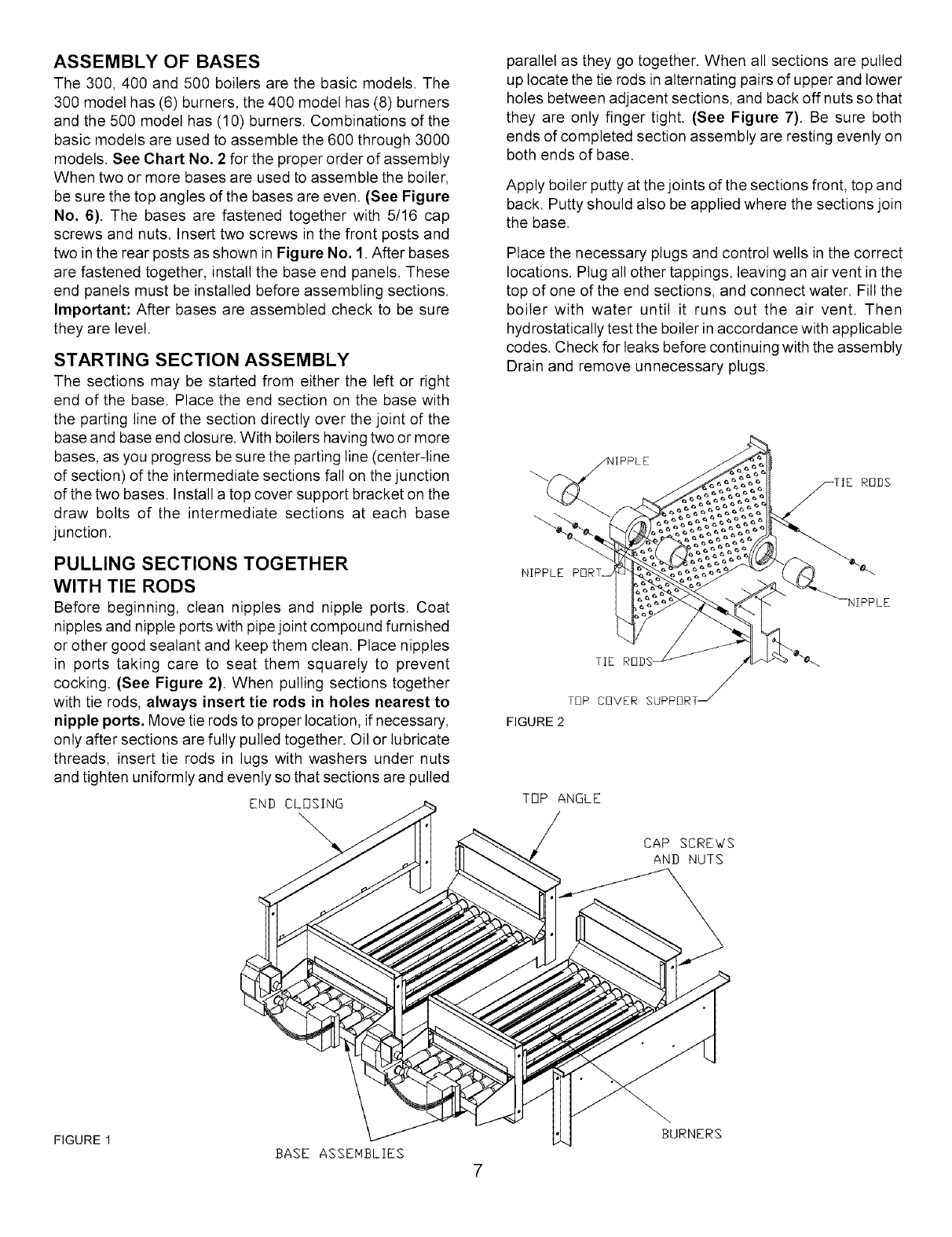
PULLING SECTIONS TOGETHER
WITH TIE RODS
Before beginning, clean nipples and nipple ports. Coat
nipples and nipple ports with pipe joint compound furnished
or other good sealant and keep them clean. Place nipples
in ports taking care to seat them squarely to prevent
cocking. (See Figure 2). When pulling sections together
with tie rods, always insert tie rods in holes nearest to
nipple ports. Move tie rods to proper location, if necessary,
only after sections are fully pulled together. Oil or lubricate
threads, insert tie rods in lugs with washers under nuts
and tighten uniformly and evenly so that sections are pulled
END CLOSING
parallel as they go together. When all sections are pulled
up locate the tie rods in alternating pairs of upper and lower
holes between adjacent sections, and back off nuts so that
they are only finger tight. (See Figure 7). Be sure both
ends of completed section assembly are resting evenly on
both ends of base.
Apply boiler putty at the joints of the sections front, top and
back. Putty should also be applied where the sections join
the base.
Place the necessary plugs and control wells in the correct
locations. Plug alt other tappings, leaving an air vent in the
top of one of the end sections, and connect water. Fitl the
boiler with water until it runs out the air vent. Then
hydrostatically test the boiler in accordance with applicable
codes. Check for leaks before continuing with the assembly
Drain and remove unnecessary plugs.
TIE
TOP COVER SUPPI]RT _
FIGURE 2
TOP ANGLE
CAP SCREWS
AND NUTS
FIGURE 1
BASE ASSEHBLIES
7
BURNERS

ITHIS PAGE INTENTIONALLY LEFT BLANK I
8
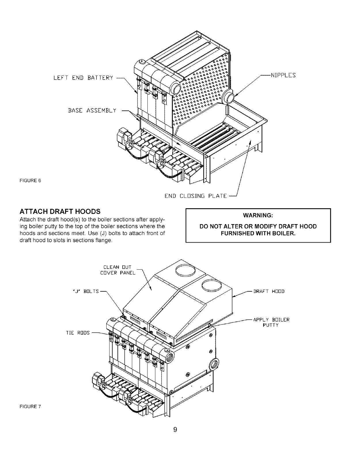
LEFT END BATTERY
BASE ASSEMBLY
FIGURE 6
ATTACH DRAFT HOODS
Attach the draft hood(s) to the boiler sections after apply-
ing boiler putty to the top of the boiler sections where the
hoods and sections meet. Use (J) bolts to attach front of
draft hood to slots in sections flange.
END CLOSING PLATE
WARNING:
DO NOT ALTER OR MODIFY DRAFT HOOD
FURNISHED WITH BOILER.
CLEAN OUT
COVER PANEL
DRAFT HOOD
APPLY BOILER
PUTTY
FIGURE 7
9
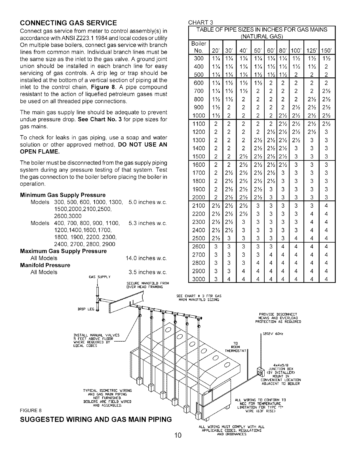
CONNECTING GAS SERVICE
Connect gas service from meter to control assembly(s) in
accordance with ANSI Z223.1 1984 and local codes or utility
On multiple base boilers, connect gas service with branch
lines from common main. Individual branch lines must be
the same size as the inlet to the gas valve. A ground joint
union should be installed in each branch line for easy
servicing of gas controls. A drip leg or trap should be
installed at the bottom of a vertical section of piping at the
inlet to the control chain, Figure 8. A pipe compound
resistant to the action of liquefied petroleum gases must
be used on all threaded pipe connections.
The main gas supply line should be adequate to prevent
undue pressure drop. See Chart No. 3 for pipe sizes for
gas mains.
To check for leaks in gas piping, use a soap and water
solution or other approved method, DO NOT USE AN
OPEN FLAME.
The boiler must be disconnected from the gas supply piping
system during any pressure testing of that system. Test
the gas connection to the boiler before placing the boiler in
operation.
Minimum Gas Supply Pressure
Models 300,500,600, 1000, 1300,
1500,2000,2100,2500,
2600,3000
Models 400, 700, 800,900, 1100,
1200,1400,1600,1700,
1800, 1900, 2200, 2300,
2400, 2700, 2800, 2900
Maximum Gas Supply Pressure
All Models
Manifold Pressure
All Models
GAS SUPPLY
l
5.0 inches w.c.
5.3 inches w.c.
14.0 inches w.c.
3.5 inches w.c.
SECURE MANIFOLD FROM
BVER HEAD FRAMING
DRIP LEG
INSTALL MANUAL VALVES
5 FEET ABOVE FLOOR
WHERE REQUIRED BY
LOCAL CODES
TYPICAL ISOMETRIC WIRING
AND GAS MAIN PIPING
NOT FURNISHED,
BOILERS ARE FIELD WIRED
AND ASSEMBLED.
FIGURE 8
SUGGESTED WIRING AND GAS MAIN PIPING
CHART 3
TABLE OF PIPE SIZES IN INCHES FOR GAS MAINS
(NATURAL GAS)
Boiler
No. 20' 30' 40' 50' 60' 80' 100' 125' 150'
300 1¼ 1¼ 1¼ 1¼ 1¼ 1¼ 1½ 1½ 1½
400 1¼ 1¼ 1¼ 1¼ 1½ 1½ 1½ 1½ 2
500 1¼ 1¼ 1¼ 1½ 1½ 1½ 2 2 2
600 1¼ 1½ 1½ 1½ 2 2 2 2 2
700 1¼ 1½ 1½ 2 2 2 2 2 2½
800 1½ 1½ 2 2 2 2 2 2½ 2½
900 1½ 2 2 2 2 2 2½ 2½ 2½
1000 1½ 2 2 2 2 2½ 2½ 2½ 2½
1100 2 2 2 2 2 2½ 2½ 2½ 2½
1200 2 2 2 2 2½ 2½ 2½ 2½ 3
1300 2 2 2 2½ 2½ 2½ 2½ 3 3
1400 2 2 2 2½ 2½ 2½ 3 3 3
1500 2 2 2½ 2½ 2½ 2½ 3 3 3
1600 2 2 2½ 2½ 2½ 2½ 3 3 3
1700 2 2½ 2½ 2½ 2½ 3 3 3 3
1800 2 2½ 2½ 2½ 2½ 3 3 3 3
1900 2 2½ 2½ 2½ 3 3 3 3 3
2000 2 2½ 2½ 2½ 3 3 3 3 3
2100 2½ 2½ 2½ 3 3 3 3 3 4
2200 2½ 2½ 2½ 3 3 3 3 4 4
2300 2½ 2½ 3 3 3 3 3 4 4
2400 2½ 2½ 3 3 3 3 3 4 4
2500 2½ 3 3 3 3 3 4 4 4
2600 3 3 3 3 3 4 4 4 4
2700 3 3 3 3 4 4 4 4 4
2800 3 3 3 4 4 4 4 4 4
2900 3 3 4 4 4 4 4 4 4
3000 3 4 4 4 4 4 4 4 4
SEE CHART # 3 FRR GAS
MAIN MANIFRLD SIZING
PROVIDE DISCONNECT
MEANS AND OVERLOAD
PROTECTION AS REQUIRED
1202V GOHz
4x4x5/8
JUNCTION BOX
(BY INSTALLER)
MOUNT IN
CONVENIENT LOCATION
ADJACENT TO BOILER
ALL WIRING TB CONFORM TO
NEC FOR TEMPERATURE
LIMITATION FOR TYPE "T*
WIRE (63F RISE)
ALL WIRING MUST COMPLY WITH ALL
APPLICABLE CODES, REGULATIONS
10 AND ORDINANCES
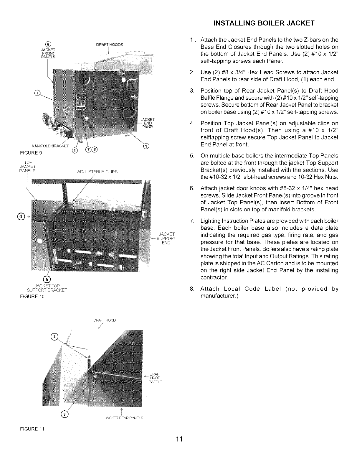
MANIFOU') BRACKET
FIGURE 9
TOP
JACKET
PANELS
@
JACKET TOP
SUPPORT BRACKET
FIGURE 10
ADJUSTABLE CLIPS
JACKET
END
PANEL
JACKET
END
.
.
3.
.
.
INSTALLING BOILER JACKET
Attach the Jacket End Panels to the two Z-bars on the
Base End Closures through the two slotted holes on
the bottom of Jacket End Panels. Use (2)#10 x 1/2"
self-tapping screws each Panel.
Use (2) #8 x 3/4" Hex Head Screws to attach Jacket
End Panels to rear side of Draft Hood, (1) each end.
Position top of Rear Jacket Panel(s) to Draft Hood
Baffle Flange and secure with (2) #10 x 1/2" self-tapping
screws. Secure bottom of Rear Jacket Panel to bracket
on boiler base using (2) #10 x 1/2" self-tapping screws.
Position Top Jacket Panel(s) on adjustable clips on
front of Draft Hood(s). Then using a #10 x 1/2"
selftapping screw secure Top Jacket Panel to Jacket
End Panel at front.
On multiple base boilers the intermediate Top Panels
are bolted at the front through the jacket Top Support
Bracket(s) previously installed with the sections. Use
the #10-32 x 1/2" slot-head screws and 10-32 Hex Nuts.
Attach jacket door knobs with #8-32 x 1/4" hex head
screws. Slide Jacket Front Panel(s) into groove in front
of Jacket Top Panel(s), then insert Bottom of Front
Panel(s) in slots on top of manifold brackets.
Lighting Instruction Plates are provided with each boiler
base. Each boiler base also includes a data plate
indicating the required gas type, firing rate, and gas
pressure for that base. These plates are located on
the Jacket Front Panels. Boilers also have a rating plate
showing the total Input and Output Ratings. This rating
plate is shipped in the AC Carton and is to be mounted
on the right side Jacket End Panel by the installing
contractor.
Attach Local Code Label (not provided by
manufacturer.)
DRAFT HOOD
BAFFLE
FIGURE 11
®E
JACKET REAR PANELS
11
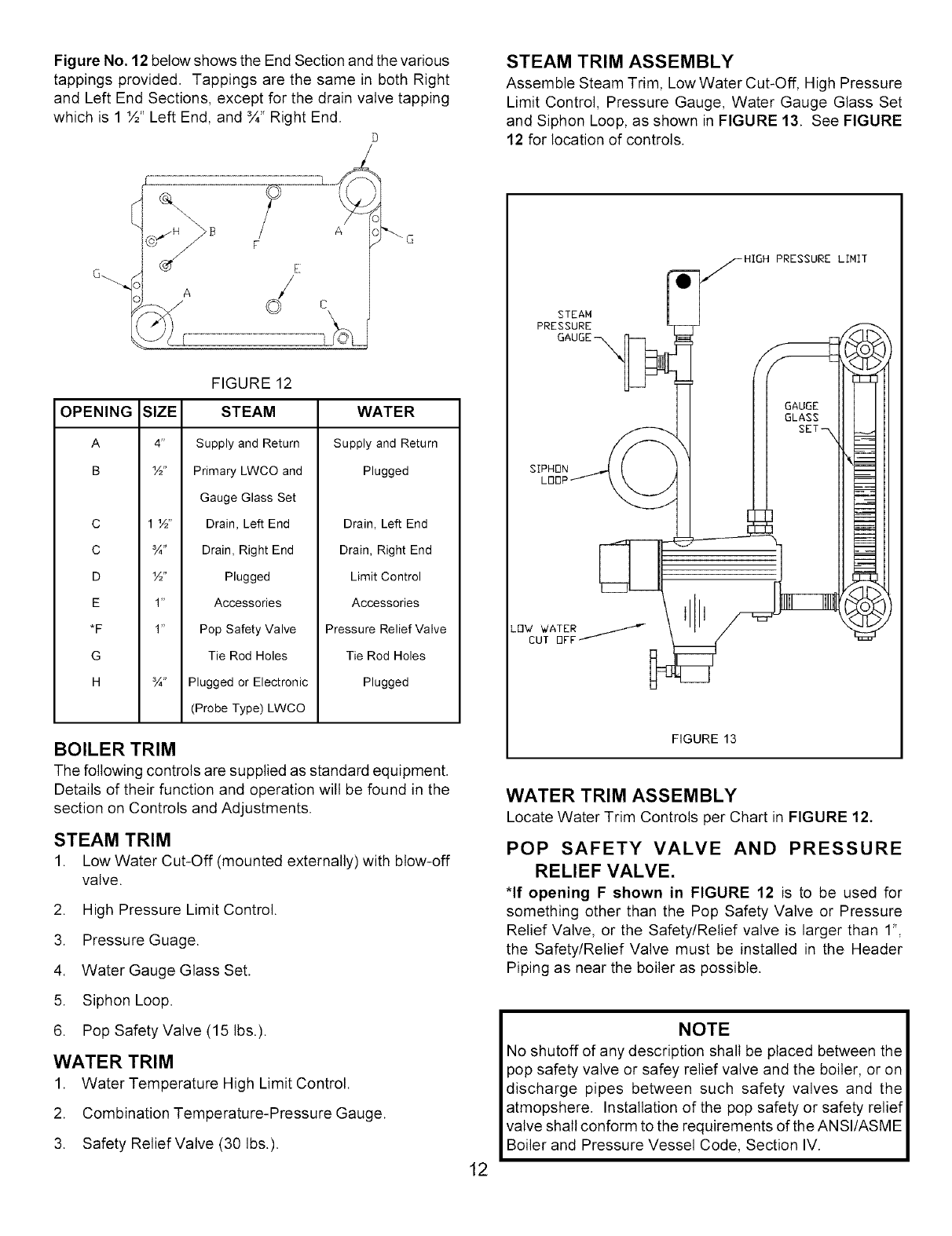
Figure No. 12 below shows the End Section and the various
tappings provided. Tappings are the same in both Right
and Left End Sections, except for the drain valve tapping
which is 1 ½" Left End, and ¾" Right End.
D
STEAM TRIM ASSEMBLY
Assemble Steam Trim, Low Water Cut-Off, High Pressure
Limit Control, Pressure Gauge, Water Gauge Glass Set
and Siphon Loop, as shown in FIGURE 13. See FIGURE
12 for location of controls.
o
FIGURE 12
OPENING SIZE STEAM
A 4" Supply and Return
B 1½. Primary LWCO and
Gauge Glass Set
C 1 1½,, Drain, Left End
C ¾" Drain, Right End
DW' Plugged
E 1" Accessories
*F 1" Pop Safety Valve
G Tie Rod Holes
H ¾" Plugged or Electronic
(Probe Type) LWCO
WATER
Supply and Return
Plugged
Drain, Left End
Drain, Right End
Limit Control
Accessories
Pressure Relief Valve
Tie Rod Holes
Plugged
BOILER TRIM
The following controls are supplied as standard equipment.
Details of their function and operation will be found in the
section on Controls and Adjustments.
STEAM TRIM
1. Low Water Cut-Off (mounted externally) with blow-off
valve.
2. High Pressure Limit Control.
3. Pressure Guage.
4. Water Gauge Glass Set.
5. Siphon Loop.
6. Pop Safety Valve (15 Ibs.).
WATER TRIM
1. Water Temperature High Limit Control.
2. Combination Temperature-Pressure Gauge.
3. Safety Relief Valve (30 Ibs.).
12
I=_HIGH PRESSURE LIMIT
STEAM
GAUGE
FIGURE 13
WATER TRIM ASSEMBLY
Locate Water Trim Controls per Chart in FIGURE 12.
POP SAFETY VALVE AND PRESSURE
RELIEF VALVE.
*If opening F shown in FIGURE 12 is to be used for
something other than the Pop Safety Valve or Pressure
Relief Valve, or the Safety/Relief valve is larger than 1",
the Safety/Relief Valve must be installed in the Header
Piping as near the boiler as possible.
NOTE
No shutoff of any description shall be placed between the
pop safety valve or safey relief valve and the boiler, or on
discharge pipes between such safety valves and the
atmopshere. Installation of the pop safety or safety relief
valve shall conform to the requirements of the AN SI/ASM E
Boiler and Pressure Vessel Code, Section IV.
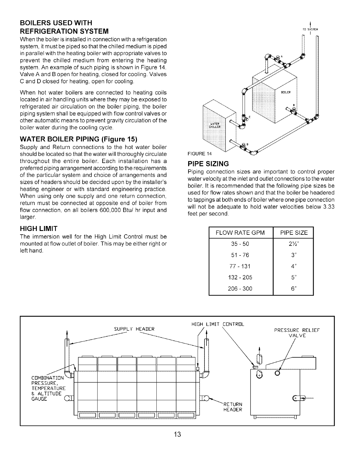
BOILERS USED WITH
REFRIGERATION SYSTEM
When the boiler is installed inconnection with a refrigeration
system, it must be piped so that the chilled medium is piped
in parallel with the heating boiler with appropriate valves to
prevent the chilled medium from entering the heating
system. An example of such piping is shown in Figure 14.
Valve A and B open for heating, closed for cooling. Valves
C and D closed for heating, open for cooling.
When hot water boilers are connected to heating coils
located in air handling units where they may be exposed to
refrigerated air circulation on the boiler piping, the boiler
piping system shall be equipped with flow control valves or
other automatic means to prevent gravity circulation of the
boiler water during the cooling cycle.
WATER BOILER PIPING (Figure 15)
Supply and Return connections to the hot water boiler
should be located so that the water will thoroughly circulate
throughout the entire boiler. Each installation has a
preferred piping arrangement according to the requirements
of the particular system and choice of arrangements and
sizes of headers should be decided upon by the installer's
heating engineer or with standard engineering practice.
When using only one supply and one return connection,
return must be connected at opposite end of boiler from
flow connection, on all boilers 600,000 Btu/hr input and
larger.
HIGH LIMIT
The immersion well for the High Limit Control must be
mounted at flow outlet of boiler. This may be either right or
left hand.
TB SYSTEM
J
FIGURE 14
PIPE SIZING
Piping connection sizes are important to control proper
water velocity at the inlet and outlet connections to the water
boiler. It is recommended that the following pipe sizes be
used for flow rates shown and that the boiler be headered
to tappings at both ends of boiler where one pipe connection
will not be adequate to hold water velocities below 3.33
feet per second.
FLOW RATE GPM
35 - 50
51 - 76
77 - 131
132 - 205
206 - 300
PIPE SIZE
2½"
3"
4"
6"
6"
SUPPLY HEADER
CBMBI
PRESSURE,
TEMPERATURE
& ALTITUDE
GAUGE (_
F----] F----] F----] F----1 F-----1 I-----]
HIGH LIHIT CONTROL
1
_RETURN
HEADER
__ PRESSURERELIEF
VALVE
13
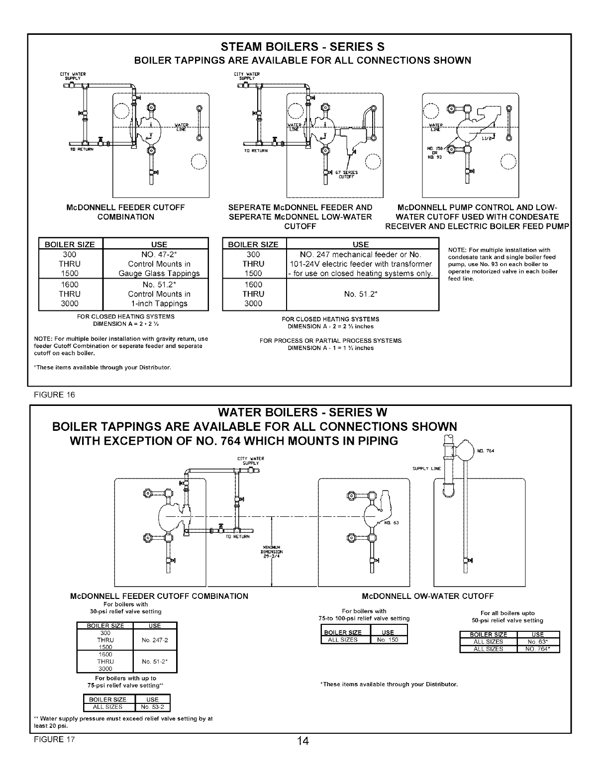
STEAM BOILERS - SERIES S
BOILER TAPPINGS ARE AVAILABLE FOR ALL CONNECTIONS SHOWN
CITY',CATER
SUPPLy
TB RET_N
CITY _,/ATgR
SUPPLy
TDRETURN
_AT R
67 SERIES _'_
-_-_-_.........
Lj
McDONNELL FEEDER CUTOFF
COMBINATION
BOILER SIZE USE
300 NO. 47-2"
THRU Control Mounts in
1500 Gauge Glass Tappings
1600 No. 51.2"
THRU Control Mounts in
3000 1-inch Tappings
FOR CLOSED HEATING SYSTEMS
DIMENSION A = 2 • 2 '/2
NOTE: For multiple boiler installation with gravity return, use
feeder Cutoff Combination or seperate feeder and seperate
cutoff on each boiler,
*These items available through your Distributor.
SEPERATE McDONNEL FEEDER AND McDONNELL PUMP CONTROL AND LOW-
SEPERATE McDONNEL LOW-WATER WATER CUTOFF USED WITH CONDESATE
CUTOFF RECEIVER AND ELECTRIC BOILER FEED PUMP
BOILER SIZE USE
300 NO. 247 mechanical feeder or No,
THRU 101-24V electric feeder with transformer
1500 for use on closed heatin 9 systems only.
1600
THRU No. 51.2*
3000
NOTE: For multiple installation with
condesate tank and single boiler feed
pump, use No, 93 on each boiler to
operate motorized valve in each boiler
feed line.
FOR CLOSED HEATING SYSTEMS
DIMENSION A _ 2 = 2 V= inches
FOR PROCESS OR PARTIAL PROCESS SYSTEMS
DIMENSION A _ 1 = 1 V=inches
FIGURE 16
WATER BOILERS - SERIES W
BOILER TAPPINGS ARE AVAILABLE FOR ALL CONNECTIONS SHOWN
WITH EXCEPTION OF NO. 764 WHICH MOUNTS IN PIPING
CITy _ATER
SUPF_Y
McDONNELL FEEDER CUTOFF COMBINATION
For boilers with
30-psi relief valve setting
_PPLY LINE_
BOILER SIZE USE
300
THRU No 247_
1500
1600
THRU No 5%2*
3000
For boilers with up to
75_psi relief valve setting**
USE
IBOILER SIZE INo 53-2IALL SIZES
** Water supply pressure must exceed relief valve setting by at
least 20 psi,
FIGURE 17 14
ND, 764
McDONNELL OW-WATER CUTOFF
For boilers with
7540 100_psi relief valve setting
IBO,LERS,ZEI USE I
IALLSIZESINolSO II
For all boilers upto
50_psi relief valve setting
BOILER SIZE I USE I
ALL SIZES No 63*
ALL SIZES NO 764*
*These items available through your Distributor.
STEAM
STEAM CROSS
HEADER
LINE
LINE
FLUSH rET
RETURN
WATER
CUT-OFF
SEE PAGE 12
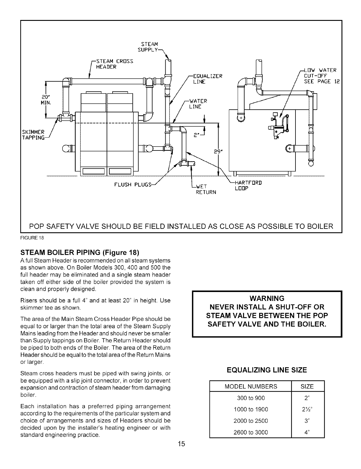
POP SAFETY VALVE SHOULD BE FIELD INSTALLED AS CLOSE AS POSSIBLE TO BOILER
FIGURE 18
STEAM BOILER PIPING (Figure 18)
A full Steam Header is recommended on all steam systems
as shown above. On Boiler Models 300,400 and 500 the
full header may be eliminated and a single steam header
taken off either side of the boiler provided the system is
clean and properly designed.
Risers should be a full 4" and at least 20" in height. Use
skimmer tee as shown.
The area of the Main Steam Cross Header Pipe should be
equal to or larger than the total area of the Steam Supply
Mains leading from the Header and should never be smaller
than Supply tappings on Boiler. The Return Header should
be piped to both ends of the Boiler. The area of the Return
Header should be equal to the total area of the Return Mains
or larger.
Steam cross headers must be piped with swing joints, or
be equipped with a slip joint connector, in order to prevent
expansion and contraction of steam header from damaging
boiler.
Each installation has a preferred piping arrangement
according to the requirements of the particular system and
choice of arrangements and sizes of Headers should be
decided upon by the installer's heating engineer or with
standard engineering practice.
15
WARNING
NEVER INSTALL A SHUT-OFF OR
STEAM VALVE BETWEEN THE POP
SAFETY VALVE AND THE BOILER.
EQUALIZING LINE SIZE
MODEL NUMBERS
300 to 900
1000 to 1900
2000 to 2500
2600 to 3000
SIZE
2"
2½"
3"
4"
FLUE CONNECTION AND VENTING
Consult local codes and gas company requirements.
Adhere to the following standard practice recommendations
for installing the flue pipe:
1 . Consult dimensional drawing for number and size of
flue pipes required for each size boiler.
2. Maintain minimum upward slope of 1/4 inch per linear
foot from the boiler to chimney.
3. Run flue pipe directly as possible. Keep turns to a
minimum. Insert flue pipe into, but not beyond, inside
wall of chimney. Do not connect into a chimney serving
an open fireplace.
4. Insulate flue pipe where it passes near combustible
material.
5. Rigidly support pipe with hangers and straps.
6. Extend chimneys at least 2 feet above any object within
radius of 15 feet, including roof.
7. Install a hood on all flue pipes which extend through
roof.
In most locations, the venting of a boiler relies on natural
draft. Inasmuch as the energy available from natural draft
is quite low, serious thought should be given to vent system
design, i.e., adequate size, use of gradual transitions, tees,
elbows, etc., close proximity of boiler and chimney. On all
boilers, the vertical risers must be at least as large as the
vent openings on the drafthood.
The boiler manufacturer makes no specific
recommendations regarding the application of draft
inducers that may be used with this boiler. If a draft inducer
is used, it is up to the installing contractor and the draft
inducer manufacturer to determine the proper application.
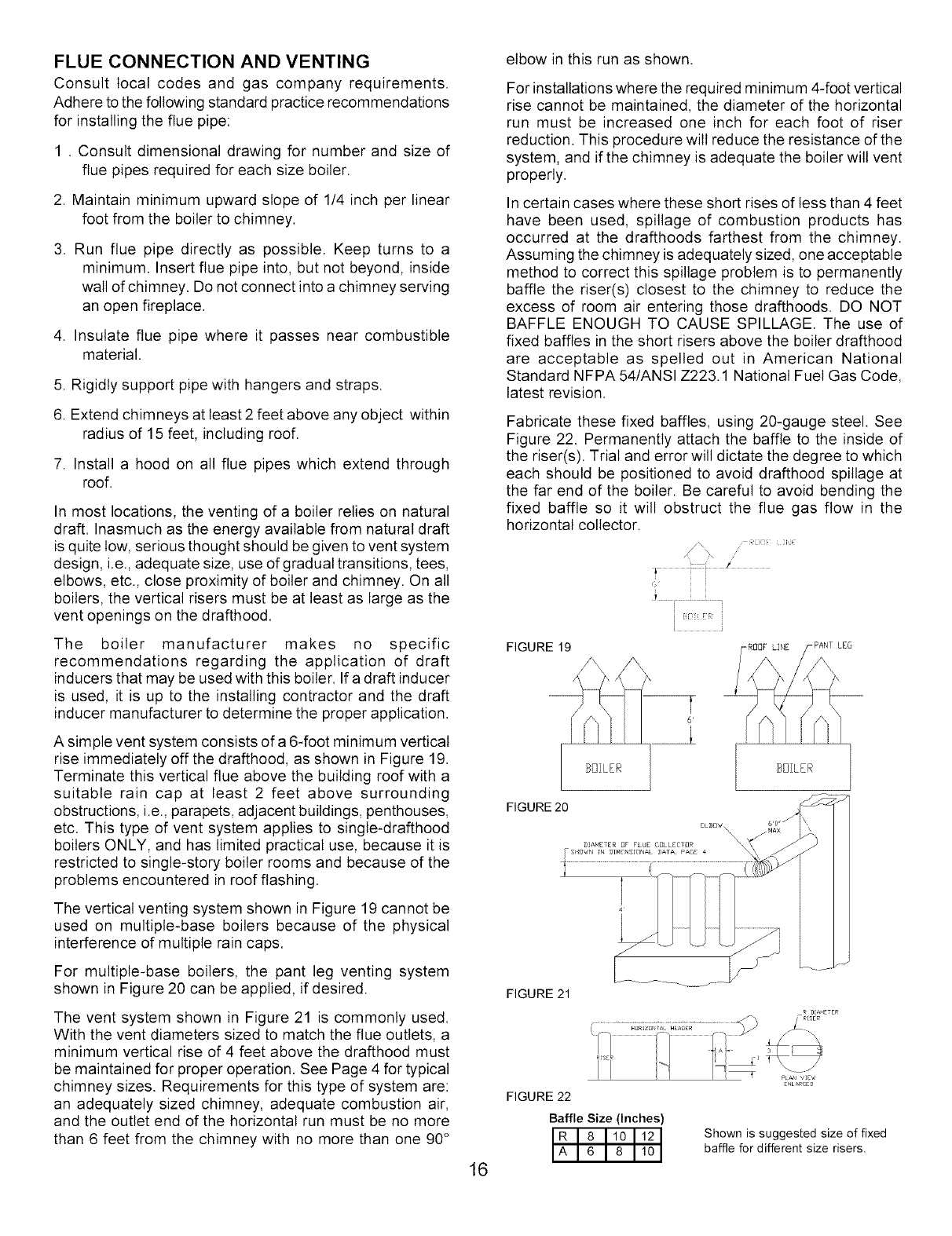
A simple vent system consists of a 6-foot minimum vertical
rise immediately off the drafthood, as shown in Figure 19.
Terminate this vertical flue above the building roof with a
suitable rain cap at least 2 feet above surrounding
obstructions, i.e., parapets, adjacent buildings, penthouses,
etc. This type of vent system applies to single-drafthood
boilers ONLY, and has limited practical use, because it is
restricted to single-story boiler rooms and because of the
problems encountered in roof flashing.
The vertical venting system shown in Figure 19 cannot be
used on multiple-base boilers because of the physical
interference of multiple rain caps.
For multiple-base boilers, the pant leg venting system
shown in Figure 20 can be applied, if desired.
The vent system shown in Figure 21 is commonly used.
With the vent diameters sized to match the flue outlets, a
minimum vertical rise of 4 feet above the drafthood must
be maintained for proper operation. See Page 4 for typical
chimney sizes. Requirements for this type of system are:
an adequately sized chimney, adequate combustion air,
and the outlet end of the horizontal run must be no more
than 6 feet from the chimney with no more than one 90°
elbow in this run as shown.
For installations where the required minimum 4-foot vertical
rise cannot be maintained, the diameter of the horizontal
run must be increased one inch for each foot of riser
reduction. This procedure wilt reduce the resistance of the
system, and if the chimney is adequate the boiler wilt vent
properly.
In certain cases where these short rises of less than 4 feet
have been used, spillage of combustion products has
occurred at the drafthoods farthest from the chimney.
Assuming the chimney is adequately sized, one acceptable
method to correct this spillage problem is to permanently
baffle the riser(s) closest to the chimney to reduce the
excess of room air entering those drafthoods. DO NOT
BAFFLE ENOUGH TO CAUSE SPILLAGE. The use of
fixed baffles in the short risers above the boiler drafthood
are acceptable as spelled out in American National
Standard NFPA 54/ANSI Z223.1 National Fuel Gas Code,
latest revision.
Fabricate these fixed baffles, using 20-gauge steel. See
Figure 22. Permanently attach the baffle to the inside of
the riser(s). Trial and error will dictate the degree to which
each should be positioned to avoid drafthood spillage at
the far end of the boiler. Be careful to avoid bending the
fixed baffle so it will obstruct the flue gas flow in the
horizontal collector.
i
/
i
i
FIGURE 19 -RODFLINE -PANTLEG
BOILER BBILER
16
FIGURE 21
R DIAMETER
, !_I _ i_1_¸_........ _ P_A._viE_
ENLARGED
FIGURE 22
Baffle Size (Inches)
Shown is suggested size of fixed
baffle for different size risers.
REMOVING EXISTING BOILER FROM
COMMON VENTING SYSTEM
When an existing boiler is removed from a common venting
system, the common venting system islikelyto be too large for
proper venting of the appliances remaining connected to it.
At the time of removal of an existing boiler, the following steps
shall be followed with each appliance remaining connected to
the common venting system placed inoperation, while the other
appliances remaining connected tothe common ventingsystem
are not in operation.
1. Seal any unused openings in the common venting system.
2. Visually inspect the venting system for proper size and
horizontal pitch and determine there is no blockage or
restriction, leakage, corrosion and other deficiencies which
could cause an unsafe condition.
Insofar as is practical, close all building doors and windows
and all doors between the space in which the appliances
remaining connected to the common venting system are
located and other spaces of the building. Turn on clothes
dryers and any appliance not connected to the common
venting system. Turn on any exhaust fans, such as range
hoods and bathroom exhausts, so they will operate at
maximum speed. Do not operate a summer exhaust fan.
Close fireplace dampers.
4. Place in operation the appliance being inspected. Follow
the lighting instructions. Adjust thermostat so appliance
wilt operate continuously.
5. Test for spillage at the draft hood relief opening after 5
minutes of main burner operation. Use the flame of a match
or candle, or smoke from a cigarette, cigar or pipe.
6. After it has been determined that each appliance remaining
connected to the common venting system properly vents
when tested as outlined above, return doors, windows,
exhaust fans, fireplace dampers and any other gas-burning
appliance to their previous conditions of use.
7. Any improper operation of the common venting system
should be corrected so the installation conforms with the
National Fuel Gas Code, ANSI Z223. l-latest issue. When
resizing any portion of the common venting system, the
common venting system should be resized to approach the
minimum size as determined using the appropriate tables
in Part 11 in the National Fuel Gas Code, ANSI Z223.1
-latest issue.
ELECTRICAL WIRING
Wiring connections are to be made in accordance with the
National Electrical Code, ANSI/NFPA 70-1984 and/or local
authority having jurisdiction. When an external electrical source
is utilized, the boiler must beelectricallygrounded inaccordance
with these requirements. Install a fused disconnect switch
between boiler and electrical panel in a convenient location.
The wiring from hightemperature limitcontrol should be secured
to the boiler jacket or gas piping to prevent an accidental
disconnect from controls.
All wiring to gas valves must betaped securely to the gas supply
lines or run in an appropriate conduit.
WARNING
TURN OFF ELECTRIC POWER AT FUSE
BOX BEFORE MAKING ANY LINE
VOLTAGE CONNECTION. FOLLOW
LOCAL ELECTRICAL CODES.
INSTALLING THERMOSTAT
The thermostat locationhas an important effect on the operation
of the boiler system. Be sure to follow the instructions included
with the thermostat. Locate the thermostat about 5 feet above
the floor on an inside wall. It should be sensing average
temperature, so avoid the following:
Dead Spots:Behind Doors
Corners and Alcoves
Hot Spots: Concealed Pipes
Fireplaces
TV Sets
Lamps
Direct Sunlight
Kitchens
Cold Spots: Concealed Pipes or Ducts
Stairwells
Drafts
Unheated Rooms on other side of walt
Keep thermostat(s) at desired room temperature. If windows
are to be opened or heat is not needed, setthermostat(s) pointer
to a lower setting.
ADJUST THERMOSTAT HEAT ANTICIPATOR
Suggested heat anticipator settings are shown in the wiring
diagrams (Figures 26, 27 and 28). Set accordingly Then follow
instructions packaged with thermostat for the final adjustment,
checking thermostat operation. When set above temperature
indicatedon the thermometer, boilerbumers should ignite.Make
certain the thermostat(s) turns off the boiler when room
temperature reaches the selected setting and starts the boiler
operating when room temperature falls a few degrees.
Finally, set the thermostat for the desired temperature. Special
conditions in building and the location of the thermostat witl
govem this setting.
STAGE FIRING MULTIPLE BASE BOILERS
1 . STEAM BOILERS
Multiple base steam boilers should not be stage fired due
to fluctuations inwater linebetween fired and unfired bases.
The boiler should be all bases on or all bases off. When
more precise control than a single thermostat offers is
required, a weather responsive duty cycle control such as
the Honeywell model ZG-54 orthe HeatTimer model MPC
or model EPU or a similar type of control should be used.
These controls determine boiler run time based on outdoor
temperature. Consult the various control manufacturers. It
stage firing is required, consult the boiler manufacturer.
2. HOT WATER BOILERS
Multiple base hot water boilers are ideal for stage firing.
Many controls are available for sequencing or stage firing
multiplebase hot water boilers.We offera W7100J Outdoor
Reset Stage Fire Control Package that wilt sequence up
to six bases, with lead/lag, soft start, adjustable reset ratio
and setpoint, and microprocessor control. This control will
fire bases as required to maintain supplywater temperature
at a desired set point, which is automatically varied based
on outdoor airtemperature. Consult the boilermanufacturer
for more information.
CAUTION
Label all wires prior to disconnection when servicing
controls. Wiring errors can cause improper and dangerous
operation. Verify proper operation after servicing.
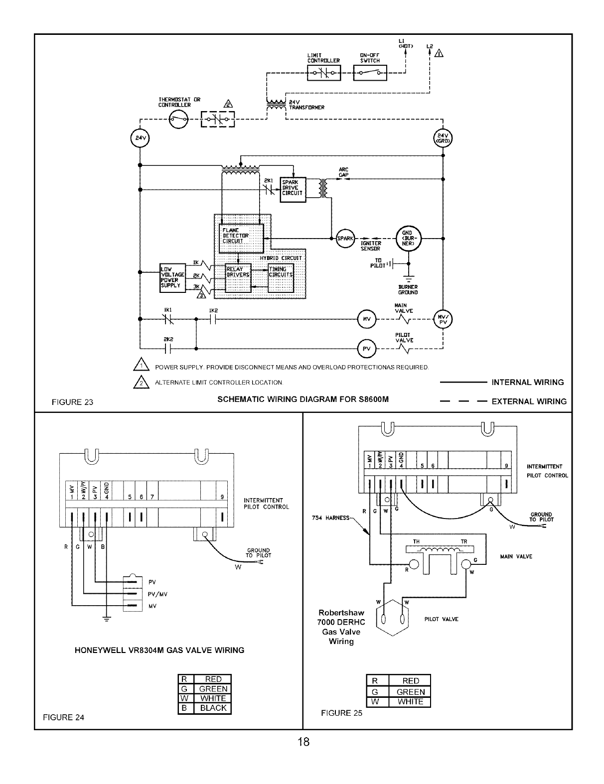
FIGURE 23
L!
(NIT) L_UNIT DN-Df'F
CBNTR_LLER SVITCH I
r......._-t--F_--q---;
I
I
Ir
TI-IERM_TAT DR
CUNTRBLLER _24V
_TR_FDRNER
F----'-I JL
...... @--L-_2,__j ......................................
_ARE
IGNITER
SENSGR
'°
PILDT i I
BURNER
MAIN
Ig| !K2 @ VALVE "_F
t----A,r....
PLDT I
2K2 @ VALVE _
___ J__ ..... _a
A POWER SUPPLY PROVIDE DISCONNECT MEANS AND OVERLOAD PROTECTIONAS REQUIRED
_ ALTERNATE LIMIT CONTROLLER LOCATION
,)
INTERNAL WIRING
SCHEMATIC WIRING DIAGRAM FOR S8600M EXTERNAL WIRING
1 2 3 4 56 7
"Rv:_v
_II INTERMITTENT
PILOT CONTROL
GROUND
_OT
W
HONEYWELL VR8304M GAS VALVE WIRING
FIGURE 24
754 NARNESS_
Robertshaw
7O0O DERHC
Gas Valve
Wiring
TH
RED
GREEN
WHITE
FIGURE 25
PILOT VALVE
INTERI,41TTENT
PILOT CONTROL
GROUND
TO PILOT
MAIN VALVE
18
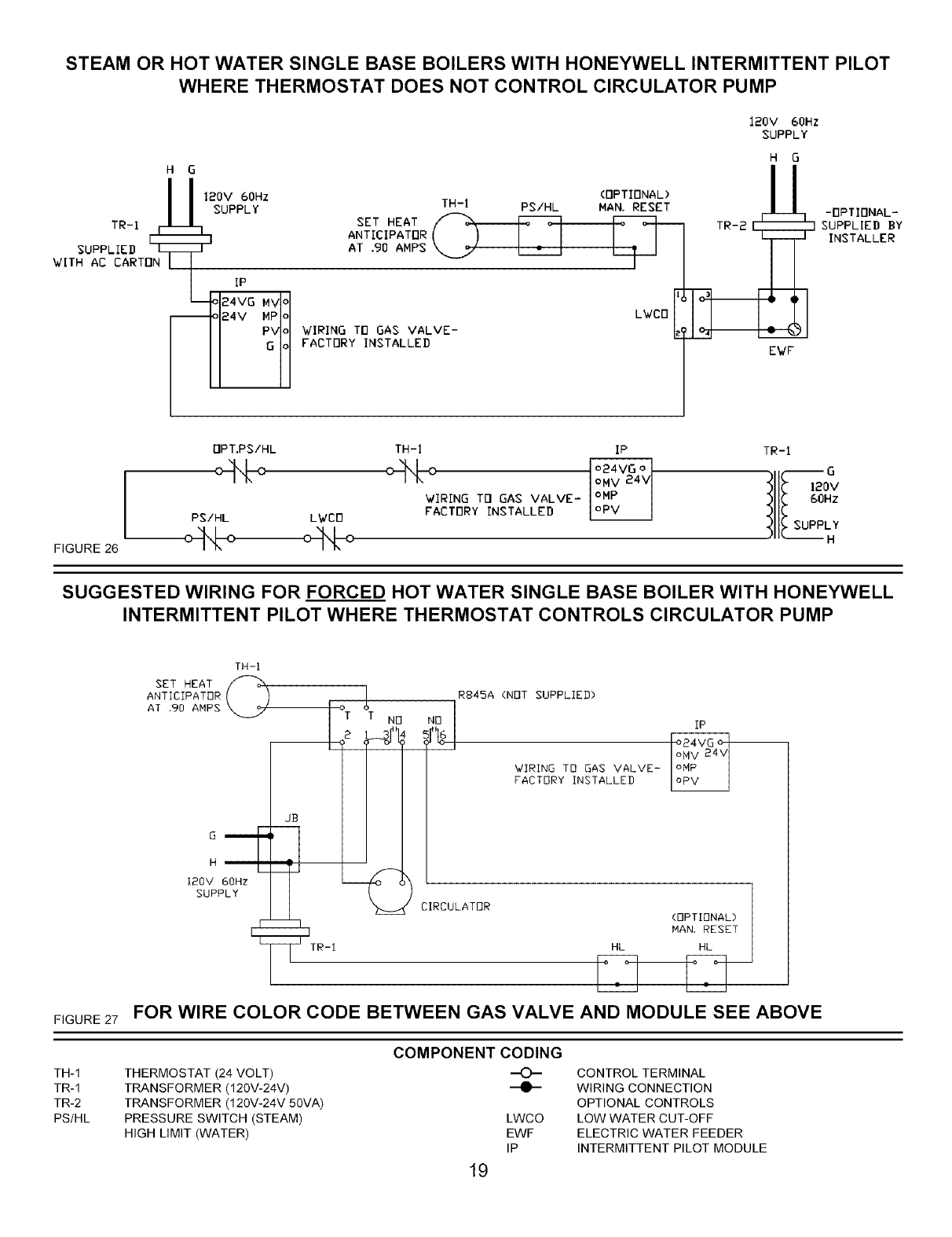
STEAM OR HOT WATER SINGLE BASE BOILERS WITH HONEYWELL INTERMITTENT PILOT
WHERE THERMOSTAT DOES NOT CONTROL CIRCULATOR PUMP
H G
1_ 120V 60Hz
SUPPLY
TR-1
SUPPLIED Lr_
WITH AC CARTON I
IP
24VG
F4v .PIo
SET HEAT
ANTICIPATOR
AT 90 AMPS
WIRING TD GAS VALVE-
FACTORY INSTALLED
(OPTIONAL)
TH-I PS/HL MAN RESET
LWCD
TR-2 E
120V 60Hz
SUPPLY
HG
-- -rlPTIONAL-
_ SUPPLIED BY
INSTALLER
EWF
FIGURE 26
rlpT.PS/HL TH-I IP TR-I
WIRING Trl GAS VALVE- _ Ill_ 60Hz
PS/HL LWCB FACTORY INSTALLED _II_ SUPPLY
SUGGESTED WIRING FOR FORCED HOT WATER SINGLE BASE BOILER WITH HONEYWELL
INTERMITTENT PILOT WHERE THERMOSTAT CONTROLS CIRCULATOR PUMP
FIGURE 27
TH-1
TR-1
TR-2
PS/HL
TH-I
SET HEAT
ANTICIPATOR
AT .90 AMPS
H
120V GOHz
SUPPLY
°T
iTR_I
R845A (NOT SUPPLIED)
WIRING TO GAS VALVE-
FACTORY INSTALLED
IP
CIRCULATOR
(OPTIONAL>
NAN, RESET
HL HL
FOR WIRE COLOR CODE BETWEEN GAS VALVE AND MODULE SEE ABOVE
THERMOSTAT (24 VOLT)
TRANSFORMER (120V-24V)
TRANSFORMER (120V-24V 50VA)
PRESSURE SWITCH (STEAM)
HIGH LIMIT (WATER)
COMPONENT CODING
-O-
--e-
LWCO
EWF
IP
19
CONTROL TERMINAL
WIRING CONNECTION
OPTIONAL CONTROLS
LOW WATER CUT-OFF
ELECTRIC WATER FEEDER
INTERMITTENT PILOT MODULE
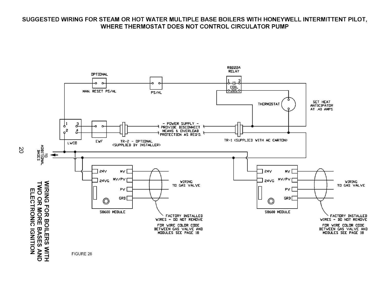
SUGGESTED WIRING FOR STEAM OR HOT WATER MULTIPLE BASE BOILERS WITH HONEYWELL INTERMITTENT PILOT,
WHERE THERMOSTAT DOES NOT CONTROL CIRCULATOR PUMP
RB222A
RELAY
OPTIONAL
MAN. RESET PS/HL PS/HL [
I
lHERMDSTAT_
__.___
O_ o--_ [I _,PROVIDE DISCONNECT
24
/2 4 I I I IIII _ MEANS & OVERLOAD
I T ° I I I LU-I 'PROTECTInN AS REO'D. _
Ii_rn EWF TR-2 - OPTIONAL TR-] PPLIE WITH AC CARTON)
0_) =i I LWL: (SUPPLIED BY INSTALLER)
NNo _-
7 _4v MYr- _ -I _4v MVr-
"1 _ 24VG MV/PV E
_r_" £ _ H PV[__ Tn GAS VALVE U PV[_
$8600 MODULE $8600 MODULE
0 0 _ FACTORY INSTALLED
Z;:Om VIRES-DO NOTREMOVE
m0FOR'dIRECOLORCODE
-- _:_ FlI BETWEEN GAS VALVE AND
MODULES SEE PAGE ]8
zoo;o
oZZ_ m FIGURE 28
_,.T-
SET HEAT
ANTICIPATOR
AT .40 AMPS
_A WIRING
TO GAS VALVE
CTDRY INSTALLED
VIRES - DO NOT REMOVE
FOR VIRE COLOR CODE
BETVEEN GAS VALVE AND
MODULES SEE PAGE 18
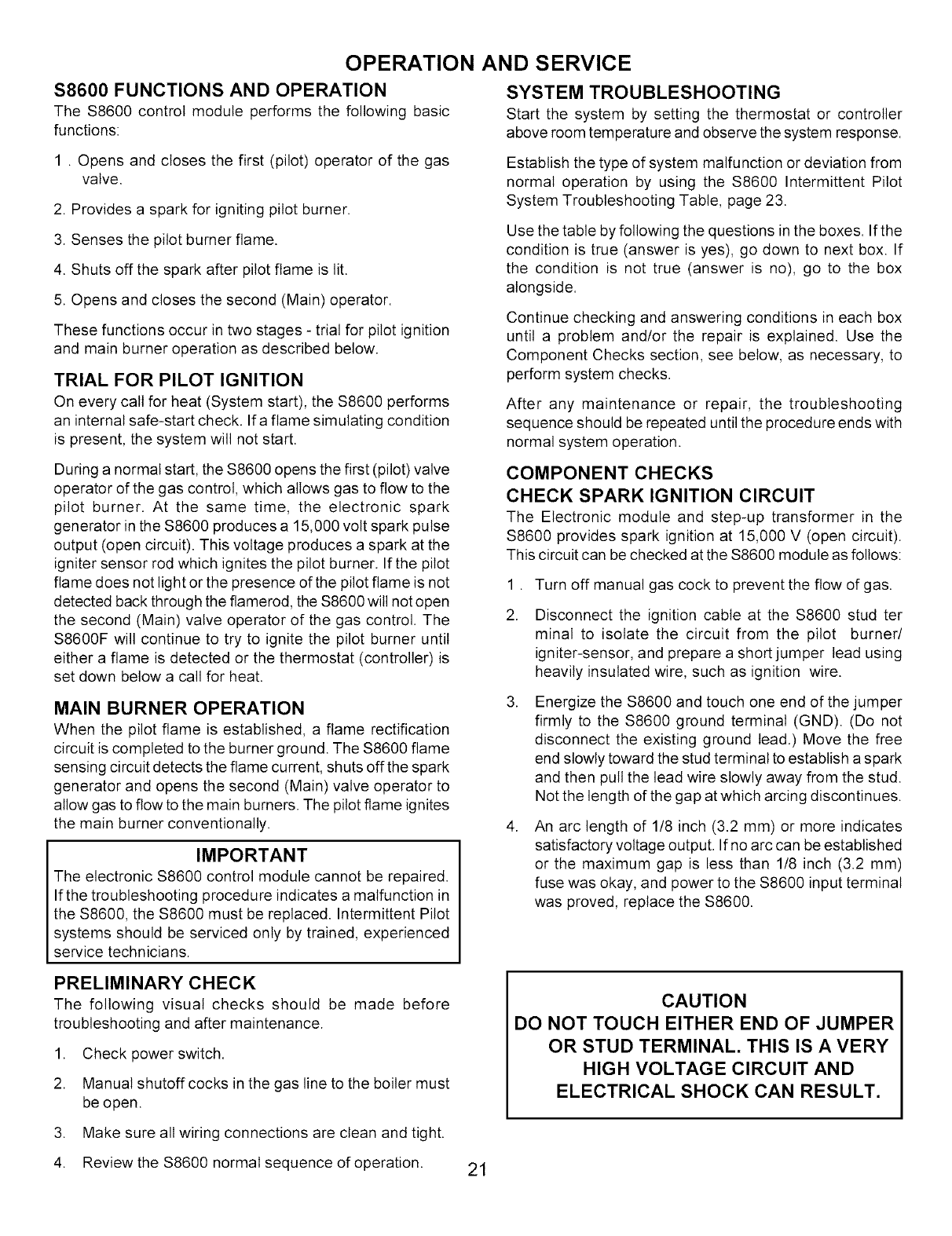
OPERATION AND SERVICE
S8600 FUNCTIONS AND OPERATION
The S8600 control module performs the following basic
functions:
SYSTEM TROUBLESHOOTING
Start the system by setting the thermostat or controller
above room temperature and observe the system response.
1 . Opens and closes the first (pilot) operator of the gas
valve.
2. Provides a spark for igniting pilot burner.
3. Senses the pilot burner flame.
4. Shuts off the spark after pilot flame is lit.
5. Opens and closes the second (Main) operator.
These functions occur in two stages - trial for pilot ignition
and main burner operation as described below.
TRIAL FOR PILOT IGNITION
On every call for heat (System start), the $8600 performs
an internal safe-start check. Ifa flame simulating condition
is present, the system will not start.
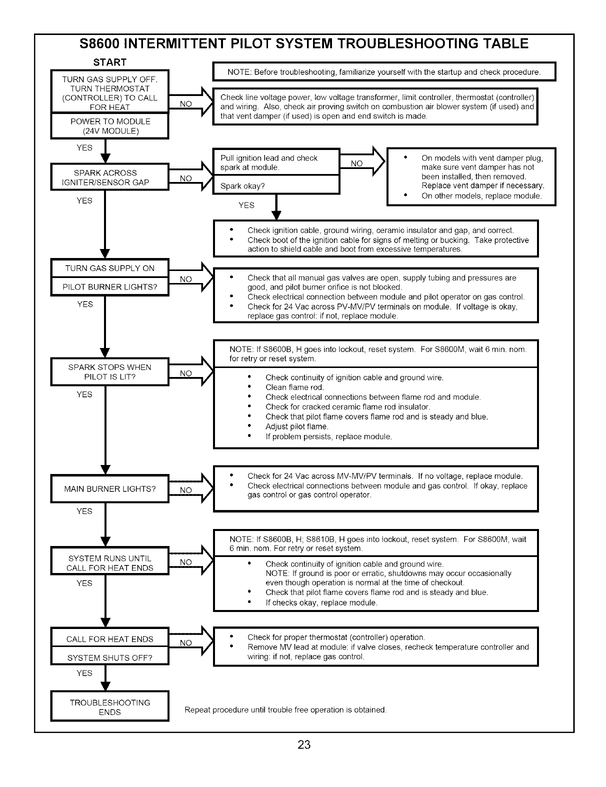
Establish the type of system malfunction or deviation from
normal operation by using the $8600 Intermittent Pilot
System Troubleshooting Table, page 23.
Use the table by following the questions in the boxes. If the
condition is true (answer is yes), go down to next box. If
the condition is not true (answer is no), go to the box
alongside.
Continue checking and answering conditions in each box
until a problem and/or the repair is explained. Use the
Component Checks section, see below, as necessary, to
perform system checks.
After any maintenance or repair, the troubleshooting
sequence should be repeated until the procedure ends with
normal system operation.
During a normal start, the $8600 opens the first (pilot) valve
operator of the gas control, which allows gas to flow to the
pilot burner. At the same time, the electronic spark
generator in the $8600 produces a 15,000 volt spark pulse
output (open circuit). This voltage produces a spark at the
igniter sensor rod which ignites the pilot burner. If the pilot
flame does not light or the presence of the pilot flame is not
detected back through the flamerod, the $8600 will not open
the second (Main) valve operator of the gas control. The
$8600F will continue to try to ignite the pilot burner until
either a flame is detected or the thermostat (controller) is
set down below a call for heat.
COMPONENT CHECKS
CHECK SPARK IGNITION CIRCUIT
The Electronic module and step-up transformer in the
$8600 provides spark ignition at 15,000 V (open circuit).
This circuit can be checked at the $8600 module as follows:
.
2.
Turn off manual gas cock to prevent the flow of gas.
Disconnect the ignition cable at the $8600 stud ter
minal to isolate the circuit from the pilot burner/
igniter-sensor, and prepare a short jumper lead using
heavily insulated wire, such as ignition wire.
MAIN BURNER OPERATION
When the pilot flame is established, a flame rectification
circuit is completed to the burner ground. The $8600 flame
sensing circuit detects the flame current, shuts off the spark
generator and opens the second (Main) valve operator to
allow gas to flow to the main burners. The pilot flame ignites
the main burner conventionally.
IMPORTANT
The electronic $8600 control module cannot be repaired.
If the troubleshooting procedure indicates a malfunction in
the $8600, the S8600 must be replaced. Intermittent Pilot
systems should be serviced only by trained, experienced
service technicians.
.
Energize the $8600 and touch one end of the jumper
firmly to the $8600 ground terminal (GND). (Do not
disconnect the existing ground lead.) Move the free
end slowly toward the stud terminal to establish a spark
and then pull the lead wire slowly away from the stud.
Not the length of the gap at which arcing discontinues.
An arc length of 1/8 inch (3.2 mm) or more indicates
satisfactory voltage output. If no arc can be established
or the maximum gap is less than 1/8 inch (3.2 ram)
fuse was okay, and power to the S8600 input terminal
was proved, replace the $8600.
PRELIMINARY CHECK
The following visual checks should be made before
troubleshooting and after maintenance.
1. Check power switch.
2. Manual shutoff cocks in the gas line to the boiler must
be open.
CAUTION
DO NOT TOUCH EITHER END OF JUMPER
OR STUD TERMINAL. THIS IS A VERY
HIGH VOLTAGE CIRCUIT AND
ELECTRICAL SHOCK CAN RESULT.
3. Make sure all wiring connections are clean and tight.
4. Review the $8600 normal sequence of operation. 21
IGNITION CABLE CHECK
Cable must not run in continuous contact with a metal
surface or spark voltage will be greatly reduced.
Connections to the stud terminal on the $8600 and on the
igniter-sensor must be clean and tight. Loose connections
may not conduct a flame current even though the ignition
spark is satisfactory. Check the electrical continuity of the
cable.
CHECK GROUNDING
A common ground is required for the pilot burner/
igniter-sensor mounting bracket, and the GND terminal of
the $8600. If the ground is poor or erratic, safety shutdown
may occur occasionally even though operation is normal
at the time of the checkout. Therefore, if nuisance
shutdowns occur, be sure to check the grounding.
STARTUP AND CHECKOUT
NOTE: If any component in the system fails, the system
will not operate. If the system does not perform as outlined
in Start System, below, refer to the $8600 Intermittent Pilot
System Trouble-shooting Table.
START SYSTEM
1. Turn on power to the $8600(s) and turn off gas supply.
2. Check $8600(s) operation as follows:
a. Set the Thermostat or controller above room
temperature to call for heat.
b. Watch for spark at the pilot burner(s). 3. Turn on
gas supply.
4. Set thermostat or controller above room temperature to
call for heat.
5. System should start as follows:
a. Spark will turn on and pilot gas valve will open at
once. Pilot burner(s) should ignite after gas reaches
the pilot burner(s).
b. Spark ignition should cut off when pilot flame is
established.
c. Main gas valve should open and main burners
should ignite after gas reaches the burner ports.
NOTE: Lightoff may not be satisfactory until the gas input
and combustion air have been adjusted.
WARNING
DO NOT OMIT THIS TEST
With main burners in operation, paint pipe joints, pilot tubing,
connections, screws, and valve(s) gaskets with a rich soap
and water solution. Bubbles indicate gas leakage. To stop
leak, tighten joints and screws or replace gaskets. Never
use a flame to check for gas leaks.
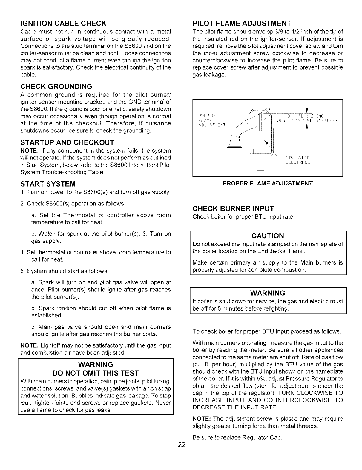
PILOT FLAME ADJUSTMENT
The pilot flame should envelop 3/8 to 1/2 inch of the tip of
the insulated rod on the igniter-sensor. If adjustment is
required, remove the pilot adjustment cover screw and turn
the inner adjustment screw clockwise to decrease or
counterclockwise to increase the pilot flame. Be sure to
replace cover screw after adjustment to prevent possible
gas leakage.
PROPER FLAME ADJUSTMENT
CHECK BURNERINPUT
Checkboiler_rproperBTUinputrate.
CAUTION
Do not exceed the Input rate stamped on the nameplate of
the boiler located on the End Jacket Panel.
Make certain primary air supply to the Main burners is
properly adjusted for complete combustion.
I WARNING I
If boiler is shut down for service, the gas and electric must
be off for 5 minutes before relighting.
To check boiler for proper BTU Input proceed as follows.
With main burners operating, measure the gas Input to the
boiler by reading the meter. Be sure all other appliances
connected to the same meter are shut off. Rate of gas flow
(cu. ft. per hour) multiplied by the BTU value of the gas
should check with the BTU Input shown on the nameplate
of the boiler. If it is within 5%, adjust Pressure Regulator to
obtain the desired flow (stem for adjustment is under the
cap in the top of the regulator). TURN CLOCKWISE TO
INCREASE INPUT AND COUNTERCLOCKWISE TO
DECREASE THE INPUT RATE.
NOTE: The adjustment screw is plastic and may require
slightly greater turning force than metal threads.
Be sure to replace Regulator Cap.
22
I
I
I
I
I
TURN GAS SUPPLY OFF.
TURN THERMOSTAT
(CONTROLLER) TO CALL
FOR HEAT
POWER TO MODULE
(24V MODULE)
S8600 INTERMITTENT PILOT SYSTEM TROUBLESHOOTING TABLE
START
I NOTE: Before troubleshooting, familiarize yourself with the startup and check procedure.
Check line voltage power, low voltage transformer, limit controller, thermostat (controller) I
and wiring. Also, check air proving switch on combustion air blower system (if used) and
that vent damper (if used) is open and end switch is made. I
YES ,
SPARK ACROSS
IGNITER/SENSOR GAP
YES 1
TURN GAS SUPPLY ON
PILOT BURNER LIGHTS?
YES 1
SPARK STOPS WHEN
PILOT IS LIT?
YES
r
MAIN BURNER LIGHTS?
SYSTEM RUNS UNTIL
CALL FOR HEAT ENDS
YES
r
I CALL FOR HEAT ENDS
SYSTEM SHUTS OFF?
IYESJ,
TROUBLESHOOTING
ENDS
Pull ignition lead and check ,,_ _ '_ • On models with vent damper plug,
spark at module. _f make sure vent damper has not
been installed, then removed.
Spark okay? Replace vent damper if necessary.
YES Jr On other models, replace module.
¥
I • Check ignition cable, ground wiring, ceramic insulator and gap, and correct. I
• Check boot of the ignition cable for signs of melting or bucking. Take protective Iaction to shield cable and boot from excessive temperatures.
• Check that all manual valves are supply tubing and are
gas open, pressures
good, and pilot burner orifice is not blocked.
• Check electrical connection between module and pilot operator on gas control.
• Check for 24 Vac across PV-MV/PV terminals on module. If voltage is okay,
replace gas control: if not, replace module.
NOTE: If S8600B, H goes into lockout, reset system. For S8600M, wait 6 min. nom.
for retry or reset system.
• Check continuity of ignition cable and ground wire.
• Clean flame rod.
• Check electrical connections between flame rod and module.
• Check for cracked ceramic flame rod insulator.
• Check that pilot flame covers flame rod and is steady and blue.
• Adjust pilot flame.
• If problem persists, replace module.
• Check for 24 Mac across MV-MV/PV terminals. If no voltage, replace module.
• Check electrical connections between module and gas control. If okay, replace
gas control or gas control operator. I
NOTE: If S8600B, H; $8610B, H goes into lockout, reset system. For S8600M, wait
6 min. nom. For retry or reset system.
• Check continuity of ignition cable and ground wire.
NOTE: If ground is poor or erratic, shutdowns may occur occasionally
even though operation is normal at the time of checkout.
• Check that pilot flame covers flame rod and is steady and blue.
• If checks okay, replace module.
• Check for proper thermostat (controller) operation.
• Remove MV lead at module: if valve closes, recheck temperature controller and
wiring: if not, replace gas control. I
I Repeat procedure until trouble free operation is obtained.
I
23
CHECKING AND
HIGH LIMIT CONTROL
While the boiler is operating, set the high limit control below
boiler water temperature and the main burners should shut
off. Return the control to the normal setting and the main
burners should start again.
PRESSURE LIMIT CONTROL
While the boiler is operating, set the pressure limit control
below the pressure in boiler and the main burners should
shut off. Return the control to the normal setting and the
main burner should start again.
LOW WATER CUT-OFF
The Low Water Cut-Off will interrupt the electrical current
to the burners when the water line in the boiler drops to a
low level. It is very important to keep the float chamber
free from sediment, a condition essential to dependability
To keep any accumulation from interfering with float action
is to "BLOW DOWN" or flush out the control regularly Do it
while the boiler is in operation. First note water level in
gauge glass. Open blow-off valve at bottom of control-,
water wilt pour out, flushing away sediment. Drain until water
is clear, about a pail, then close valve. If water level in
gauge glass has dropped, add water to boiler to restore
level.
ADJUSTING
qualified service technician to replace the relief valve and
inspect the heating system to determine the cause, as this
may indicate an equipment malfunction.
This valve should be tested every month during periods of
boiler operation, and at the beginning and end of any
extended non-service period. Prior to testing, make certain
discharge pipe is properly connected to valve outlet and
arranged so as to contain and safely dispose of boiler
discharge. Test at normal system operating pressure. Hold
the trip lever fully open for at least five seconds in order to
flush free any sediment that may lodge on the valve seat.
Then permit the valve to snap shut.
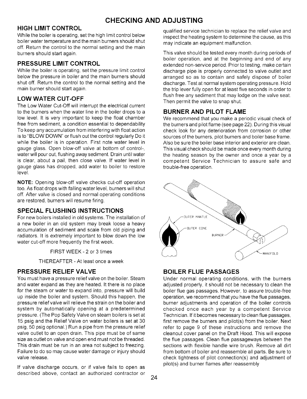
BURNER AND PILOT FLAME
We recommend that you make a periodic visual check of
the burners and pilot flame (see page 22). During this visual
check look for any deterioration from corrosion or other
sources of the burners, pilot burners and boiler base frame.
Also be sure the boiler base interior and exterior are clean.
This visual check should be made once every month during
the heating season by the owner and once a year by a
competent Service Technician to assure safe and
trouble-free operation.
NOTE: Opening blow-off valve checks cut-off operation
too. As float drops with falling water level, burners will shut
off. After valve is closed and normal operating conditions
are restored, burners will resume firing.
SPECIAL FLUSHING INSTRUCTIONS
For new boilers installed in old systems. The installation of
a new boiler in an old system may break loose a heavy
accumulation of sediment and scale from old piping and
radiators. It is extremely important to blow down the low
water cut-off more frequently the first week.
FIRST WEEK - 2 or 3 times
_DUTER MANTLE
_DUTER CONE
BURNER _
THEREAFTER - At least once a week
PRESSURE RELIEF VALVE
You must have a pressure relief valve on the boiler. Steam
and water expand as they are heated. It there is no place
for the steam or water to expand into, pressure will build
up inside the boiler and system. Should this happen, the
pressure relief valve will relieve the strain on the boiler and
system by automatically opening at a predetermined
pressure. (The Pop Safety Valve on steam boilers is set at
15 psig and the Relief Valve on water boilers is set at 30
psig, 50 psig optional.) Run a pipe from the pressure relief
valve outlet to an open drain. This pipe must be of same
size as outlet on valve and open end must not be threaded.
This drain must be run in an area not subject to freezing.
Failure to do so may cause water damage or injury should
valve release.
If valve discharge occurs, or if valve fails to open as
described above, contact an authorized contractor or
BOILER FLUE PASSAGES
Under normal operating conditions, with the burners
adjusted properly, it should not be necessary to clean the
boiler flue gas passages. However, to assure trouble-free
operation, we recommend that you have the flue passages,
burner adjustments and operation of the boiler controls
checked once each year by a competent Service
Technician. If it becomes necessary to clean flue passages,
first remove the burners and pilot(s) from the boiler. Next
refer to page 9 of these instructions and remove the
cleanout cover panel on the Draft Hood. This wilt expose
the flue passages. Clean flue passageways between the
sections with flexible handle wire brush. Remove all dirt
from bottom of boiler and reassemble all parts. Be sure to
check tightness of pilot connection(s) and adjustment of
pilot(s) and burner flames after reassembly
24
VENTING SYSTEM
The vent system is a very important part of the heating
system. No boiler, however efficient its design, can perform
satisfactorily if the chimney that serves it is inadequate.
Check your chimney to make sure that it is the right size,
properly constructed, clean and in good condition to ensure
proper combustion and THAT NO HAZARD WILL
DEVELOP You must also provide enough FRESH AIR FOR
COMBUSTION. LACK OF ENOUGH OXYGEN WILL
CREATE A HAZARD. If your building is of tight construction,
it may be necessary to add a FRESH AIR DUCT to provide
the OXYGEN required (see page 6).
AT LEAST ONCE A MONTH DURING HEATING SEASON
check to see that the sections of vent pipe are secure at all
joints and fittings. There should be at least two (2) sheet
metal screws per joint.
Check to see that the vent pipe slopes at least 1/4" per foot
up from the boiler to the chimney. The vent pipe should be
securely fastened to prevent sagging.
The Vent Pipe should also be checked for any deterioration
from corrosion or any other sources. See venting
instructions on page 16.
CLEANING THE NEW STEAM BOILER
New steam boilers must be cleaned previous to or during
the first few days of use in order to ensure efficient
operation. The grease or oil used to lubricate the cutting
tools or push nipples during the erection of new piping
systems picks up sand and dirt causing a scum of fine
particles and grease to accumulate on the surface of the
water in all new boilers, The heavier particles carried in
the grease may settle to the bottom of the boiler and form
sludge. This condition, if permitted to remain in the boiler,
tends to prevent the generation of steam, produces foaming
and causes an unsteady water line. This unavoidable
accumulation of oil and grease should be removed by
blowing off the boiler as follows:
Install a surface blow-off connection of at least 11/4'
nominal pipe size in boiler using the Skimming Tee
shown on page 15. The blow-off line should extend to
within 18" of the floor or to the sewer.
a. Insert a valve in the line close to the boiler.
2. Bring the water line to the center of the outlet.
a. Raise the temperature to a point just below steaming.
b. While the burners are on, open the valve in the skim
line and then slowly feed clean water into the boiler
adjusting the inlet water so that the boiler water
remains hot.
c. Continue skimming until the water is clean.
3. Close valves in boiler feed line and skim line.
4. Bring the pressure in the boiler to about 10 Ibs.
a. Turn off the burners.
b. Open the bottom drain valve permitting all the water
to drain from boiler.
5. After the boiler has cooled-, fill and flush out several
times.
6. Fill to proper water level and ready for normal service.
NOTE: Use of soda or any alkali, vinegar or any acid is not
recommended for cleaning heating boilers because it is
difficult to completely remove them and injury may occur
after the cleaning process has been completed.
BOILER WATER TREATMENT
In closed hot water heating systems, negligible amounts
of make up water are used, and water treatment is not
required.
In steam systems where the system is tight, free from leaks,
and all the steam is returned to the boiler as condensate,
the amount of make up water is small. Again, water
treatment is not required.
On steam systems with less than 90% of the steam being
returned as condensate, or with very hard or corrosive make
up water, treatment may be desirable. Follow the
recommendations of the ASME (American Society of
Mechanical Engineers) Boiler and Pressure Vessel Code,
Section Vl, latest version.
BETWEEN HEATING SEASONS
Boilers should not be drained between heating seasons.
Boilers in closed hot water heating systems may be left as
is. Steam boilers should be entirely filled with water during
the summer months to exclude air.
25
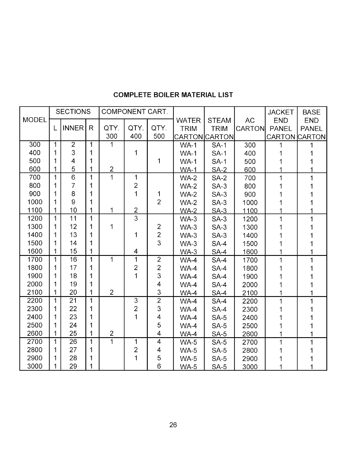
COMPLETE BOILER MATERIAL LIST
MODEL
SECTIONS
L INNER R
300 1 2 1
400 1 3 1
500 1 4 1
600 1 5 1
700 1 6 1
800 1 7 1
900 1 8 1
1000 1 9 1
1100 1 10 1
1200 1 11 1
1300 1 12 1
1400 1 13 1
1500 1 14 1
1600 1 15 1
1700 1 16 1
1800 1 17 1
1900 1 18 1
2000 1 19 1
2100 1 20 1
2200 1 21 1
2300 1 22 1
2400 1 23 1
2500 1 24 1
2600 1 25 1
2700 1 26 1
2800 1 27 1
2900 1 28 1
3000 1 29 1
COMPONENT CART.
QTY. QTY. QTY.
300 400 500
1
1
1
2
1 1
2
1 1
2
1 2
3
1 2
1 2
3
4
1 1 2
2 2
1 3
4
2 3
3 2
2 3
1 4
5
2 4
1 1 4
2 4
1 5
6
WATER
TRIM
CARTON
WA-1
WA-1
WA-1
WA-1
WA-2
WA-2
WA-2
WA-2
WA-2
WA-3
WA-3
WA-3
WA-3
WA-3
WA-4
WA-4
WA-4
WA-4
WA-4
WA-4
WA-4
WA-4
WA-4
WA-4
WA-5
WA-5
WA-5
WA-5
STEAM
TRIM
CARTON
SA-1
SA-1
SA-1
SA-2
SA-2
SA-3
SA-3
SA-3
SA-3
SA-3
SA-3
SA-3
SA-4
SA-4
SA-4
SA-4
SA-4
SA-4
SA-4
SA-4
SA-4
SA-5
SA-5
SA-5
SA-5
SA-5
SA-5
SA-5
AC
CARTON
3OO
4OO
5OO
6OO
7OO
8OO
9OO
1000
1100
1200
1300
1400
1500
1600
1700
1800
1900
2000
2100
2200
2300
2400
2500
2600
2700
2800
2900
3000
JACKET
END
PANEL
CARTON
1
1
1
1
1
1
1
1
1
1
1
1
1
1
1
1
1
1
1
1
1
1
1
1
1
1
1
1
BASE
END
PANEL
CARTON
1
1
1
1
1
1
1
1
1
1
1
1
1
1
1
1
1
1
1
1
1
1
1
1
1
1
1
1
26
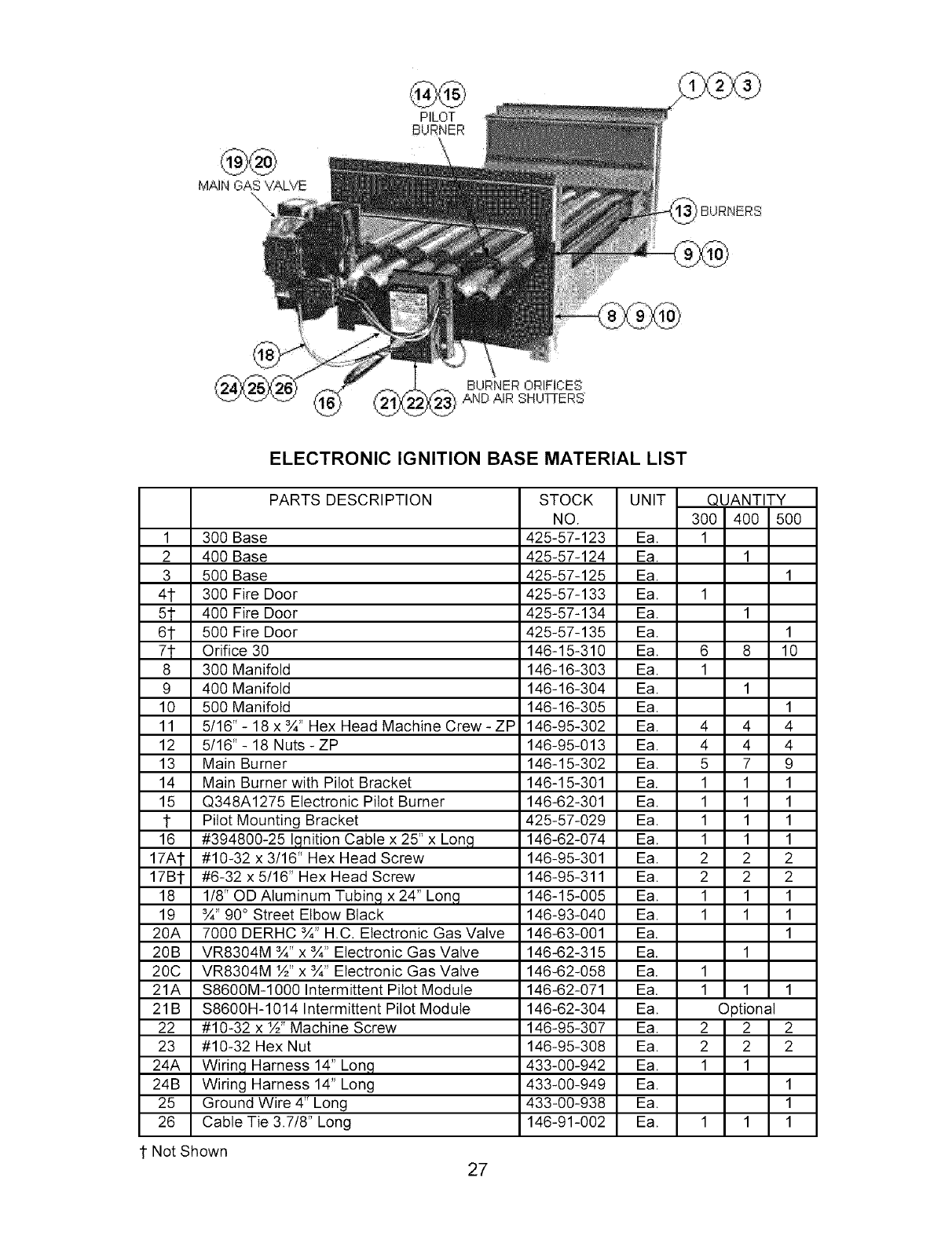
MAiN GAS VALVE
",\:
PILOT
BURNER
IBURNERS
BURNER ORIFICES
AND AIR SHU'Fi-ERS
ELECTRONIC IGNITION BASE MATERIAL LIST
PARTS DESCRIPTION
1 300 Base
2 400 Base
3 500 Base
4t 300 Fire Door
51- 400 Fire Door
61 500 Fire Door
71- Orifice 30
8 300 Manifold
9 400 Manifold
10 500 Manifold
11 5/16" - 18 x ¾" Hex Head Machine Crew - ZP
12 5/16"- 18 Nuts-ZP
13 Main Burner
14 Main Burner with Pilot Bracket
15 Q348A1275 Electronic Pilot Burner
1 Pilot Mounting Bracket
16 #394800-25 I,qnition Cable x 25" x Lon,q
17A1- #10-32 x 3/16" Hex Head Screw
17B1- #6-32 x 5/16" Hex Head Screw
18 1/8" OD Aluminum Tubin,q x 24" Lon,q
19 ¾" 90° Street Elbow Black
20A 7000 DERHC ¾" H.C. Electronic Gas Valve
20B VR8304M ¾" x ¾" Electronic Gas Valve
20C VR8304M ½" x ¾" Electronic Gas Valve
21A S8600M-1000 Intermittent Pilot Module
21B $8600H-1014 Intermittent Pilot Module
22 #10-32 x ½" Machine Screw
23 #10-32 Hex Nut
24A Wirin,q Harness 14" Lon,q
24B Wiring Harness 14" Long
25 Ground Wire 4" Long
26 Cable Tie 3.7/8" Long
STOCK UNIT QUANTITY
NO. 300 400 500
425-57-123 Ea. 1
425-57-124 Ea. 1
425-57-125 Ea. 1
425-57-133 Ea. 1
425-57-134 Ea. 1
425-57-135 Ea. 1
146-15-310 Ea. 6 8 10
146-16-303 Ea. 1
146-16-304 Ea. 1
146-16-305 Ea. 1
146-95-302 Ea. 4 4 4
146-95-013 Ea. 4 4 4
146-15-302 Ea. 5 7 9
146-15-301 Ea. 1 1 1
146-62-301 Ea. 1 1 1
425-57-029 Ea. 1 1 1
146-62-074 Ea. 1 1 1
146-95-301 Ea. 2 2 2
146-95-311 Ea. 2 2 2
146-15-005 Ea. 1 1 1
146-93-040 Ea. 1 1 1
146-63-001 Ea. 1
146-62-315 Ea. 1
146-62-058 Ea. 1
146-62-071 Ea. 1 1 1
146-62-304 Ea. Optional
146-95-307 Ea. 2 2 2
146-95-308 Ea. 2 2 2
433-00-942 Ea. 1 1
433-00-949 Ea. 1
433-00-938 Ea. 1
146-91-002 Ea. 1 1 1
1 Not Shown 27
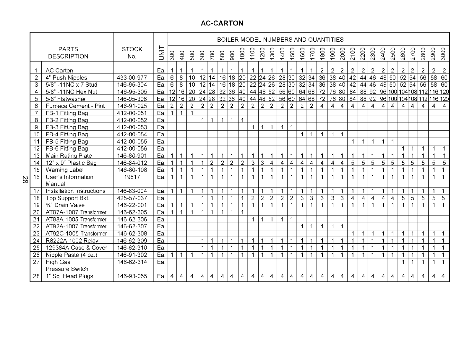
AC-CARTON
PARTS
DESCRIPTION
STOCK
No.
1 AC Carton
2 4" Push Nipples
3 5/8" -11NC x 7 Stud
4 5/8"-11NC Hex Nut
5 5/8" Flatwasher
6 Furnace Cement - Pint
7 FB-1 Fitting Ba.q
8 FB-2 Fitting Bag
9 FB-3 Fitting Bag
10 FB-4 Fitting Ba.q
11 FB-5 Fitting Bag
12 FB-6 Fitting Bag
13 Main Rating Plate
14 12" x 9" Plastic Bag
15 Warning Label
16 User's Information
Manual
17 Installation Instructions
18 Top Support Bkt.
19 ¾" Drain Valve
20 AT87A-1007 Transformer
21 AT88A-1005 Transformer
22 AT92A-1007 Transformer
23 AT92C-1005 Transformer
24 R8222A-1002 Relay
25 129384A Case & Cover
26 Nipple Paste (4 oz.)
27 High Gas
Pressure Switch
28 1" Sq. Head Plugs
433-00-977
146-95-304
146-95-305
146-95-306
146-91-025
412-00-051
412-00-052
412-00-053
412-00-054
412-00-055
412-00-056
146-80-901
146-84-012
146-80-108
19817
146-83-004
425-57-037
146-22-001
146-62-305
146-62-306
146-62-307
146-62-308
146-62-309
146-62-310
146-91-302
146-62-314
Ea. 1 1 1 1 1 1 1 1 1 1 1 1 1 1 1 2 2 2 2 2 2 2 2 2 2 2 2 2
Ea. 6 8 10 12 14 16 18 20 22 24 26 28 30 32 34 36 38 40 42 44 46 48 50 52 54 56 58 60
Ea. 6 8 10 12 14 16 18 20 22 24 26 28 30 32 34 36 38 40 42 44 46 48 50 52 54 56 58 60
Ea. 12 16 20 24 28 32 36 40 44 48 52 56 60 64 68 72 76 80 84 88 92 96 10010410811211612C
Ea. 12 16 20 24 28 32 36 40 44 48 52 56 60 64 68 72 76 80 84 88 92 96 100 104108 112 11612C
Ea. 2 2 2 2 2 2 2 2 2 2 2 2 2 2 2 4 4 4 4 4 4 4 4 4 4 4 4 4
Ea. 1 1 1
Ea.
Ea.
Ea.
Ea.
Ea.
11111
11111
11111
11111
11111
Ea. 1 1 1 1 1 1 1 1 1 1 1 1 1 1 1 1 1 1 1 1 1 1 1 1 1 1 1 1
Ea. 1 1 1 1 2 2 2 2 3 3 4 4 4 4 4 4 4 4 5 5 5 5 5 5 5 5 5 5
Ea. 1 1 1 1 1 1 1 1 1 1 1 1 1 1 1 1 1 1 1 1 1 1 1 1 1 1 1 1
Ea. 1 1 1 1 1 1 1 1 1 1 1 1 1 1 1 1 1 1 1 1 1 1 1 1 1 1 1 1
Ea. 1 1 1 1 1 1 1 1 1 1 1 1 1 1 1 1 1 1 1 1 1 1 1 1 1 1 1 1
Ea. 1 1 1 1 1 2 2 2 2 2 3 3 3 3 3 4 4 4 4 4 5 5 5 5 5
Ea. 1 1 1 1 1 1 1 1 1 1 1 1 1 1 1 1 1 1 1 1 1 1 1 1 1 1 1 1
Ea. 11111111
Ea. 11111
Ea. 11111
Ea. 1 1 1 1 1 1 1 1 1 1
Ea. 1 1 1 1 1 1 1 1 1 1 1 1 1 1 1 1 1 1 1 1 1 1 1 1 1
Ea. 1 1 1 1 1 1 1 1 1 1 1 1 1 1 1 1 1 1 1 1 1 1 1 1 1
Ea. 1 1 1 1 1 1 1 1 1 1 1 1 1 1 1 1 1 1 1 1 1 1 1 1 1 1 1 1
Ea. 11111
146-93-055 Ea. 4 4 4 4 4 4 4 4 4 4 4 4 4 4 4 4 4 4 4 4 4 4 4 4 4 4 4 4
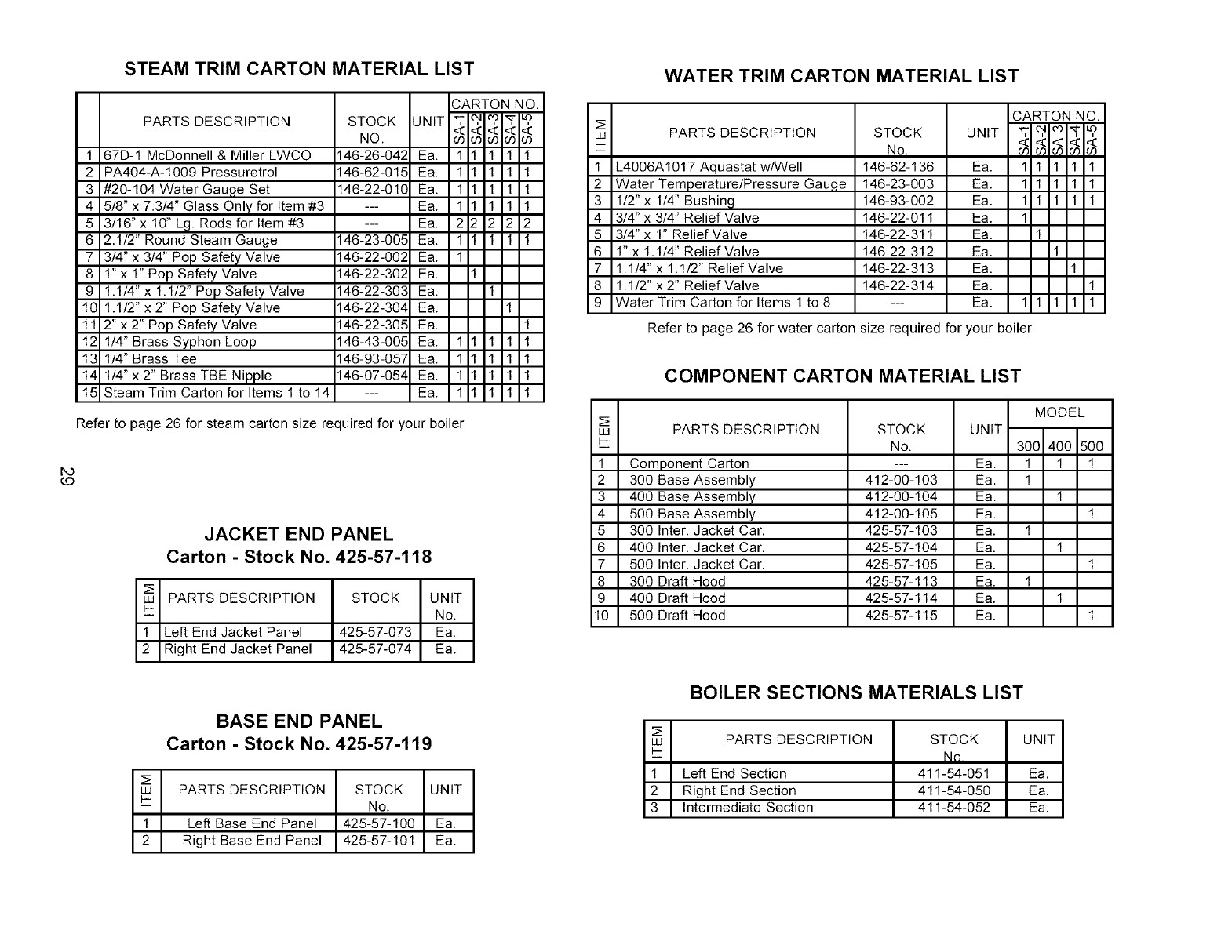
STEAM TRIM CARTON MATERIAL LIST
PARTS DESCRIPTION
1 67D-1 McDonnell & Miller LWCO
2 PA404-A-1009 Pressuretrol
3 #20-104 Water Gau,qe Set
4 5/8" x 7.3/4" Glass Only for Item #3
5 3/16" x 10" Lg. Rods for Item #3
6 2.1/2" Round Steam Gauge
7 3/4" x 3/4" Pop Safety Valve
8 1" x 1" Pop Safety Valve
9 1.1/4" x 1.1/2" Pop Safety Valve
10 1.1/2" x 2" Pop Safety Valve
11 2" x 2" Pop Safety Valve
12 1/4" Brass Syphon Loop
13 1/4" Brass Tee
14 1/4" x 2" Brass TBE Nipple
15 Steam Trim Carton for Items 1 to 14
STOCK UNIT
NO.
CARTON NO.
<<<<<
11111
11111
11111
11111
22222
11111
1
1
1
146-26-042 Ea.
146-62-015 Ea.
146-22-010 Ea.
--- Ea.
--- Ea.
146-23-005 Ea.
146-22-002 Ea.
146-22-302 Ea.
146-22-303 Ea.
146-22-304 Ea.
146-22-305 Ea.
146-43-005 Ea.
146-93-057 Ea.
146-07-054 Ea.
--- Ea.
111
111
111
111
1
1
1 1
1 1
1 1
1 1
Refer to page 26 for steam carton size required for your boiler
DO
(D
JACKET END PANEL
Carton - Stock No. 425-57-118
PARTS DESCRIPTION STOCK UNIT
i_ No.
1Left End Jacket Panel 425-57-073 Ea.
2 Right End Jacket Panel 425-57-074 Ea.
BASE END PANEL
Carton - Stock No. 425-57-119
LU PARTS DESCRIPTION STOCK UNIT
I-
-- No.
1 Left Base End Panel 425-57-100 Ea.
2 Right Base End Panel 425-57-101 Ea.
WATER TRIM CARTON MATERIAL LIST
LU PARTS DESCRIPTION
I-
i
1 L4006A1017 Aquastat w/Well
2 Water Temperature/Pressure Gauge
3 1/2" x 1/4" Bushing
4 3/4" x 3/4" Relief Valve
5 3/4" x 1" Relief Valve
6 l"x 1.1/4" Relief Valve
7 1.1/4"x 1.1/2" Relief Valve
8 1.1/2" x 2" Relief Valve
9 Water Trim Carton for Items 1 to 8
STOCK UNIT
No.
146-62-136 Ea.
146-23-003 Ea.
146-93-002 Ea.
146-22-011 Ea.
146-22-311 Ea.
146-22-312 Ea.
146-22-313 Ea.
146-22-314 Ea.
--- Ea.
CARTON NO.
",-- O, ¢O ,_:l" _
4<44_:
0")0':.0300:,0
11111
11111
11111
1
1
1
1
1
11111
Refer to page 26 for water carton size required for your boiler
COMPONENT CARTON MATERIAL LIST
LU PARTS DESCRIPTION
I-
i
1 Component Carton
2 300 Base Assembly
3 400 Base Assembly
4 500 Base Assembly
5 300 Inter. Jacket Car.
6 400 Inter. Jacket Car.
7 500 Inter. Jacket Car.
8 300 Draft Hood
9 400 Draft Hood
10 500 Draft Hood
STOCK UNIT
No.
--- Ea.
412-00-103 Ea.
412-00-104 Ea.
412-00-105 Ea.
425-57-103 Ea.
425-57-104 Ea.
425-57-105 Ea.
425-57-113 Ea.
425-57-114 Ea.
425-57-115 Ea.
MODEL
300 400 500
1 1 1
1
1
1
1
1
1
1
1
1
BOILER SECTIONS MATERIALS LIST
;E
LU PARTS DESCRIPTION STOCK UNIT
Ng,
1 Left End Section 411-54-051 Ea.
2 Right End Section 411-54-050 Ea.
3 Intermediate Section 411-54-052 Ea.
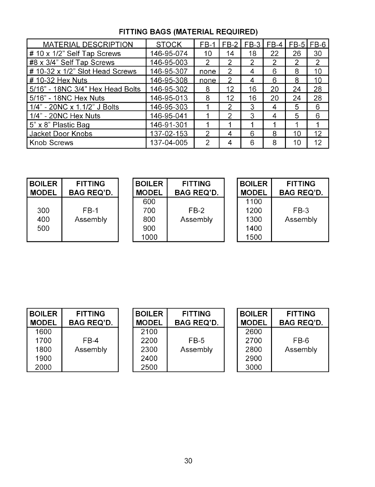
FITTING BAGS (MATERIAL REQUIRED)
MATERIAL DESCRIPTION
# 10 x 1/2" Self Tap Screws
#8 x 3/4" Self Tap Screws
# 10-32 x 1/2" Slot Head Screws
# 10-32 Hex Nuts
5/16"- 18NC 3/4" Hex Head Bolts
5/16"- 18NC Hex Nuts
1/4" - 20NC x 1.1/2" J Bolts
1/4" - 20NC Hex Nuts
5" x 8" Plastic Bag
Jacket Door Knobs
Knob Screws
STOCK FB-1 FB-2 FB-3 FB-4 FB-5 FB-6
146-95-074 10 14 18 22 26 30
146-95-003 2 2 2 2 2 2
146-95-307 none 2 4 6 8 10
146-95-308 none 2 4 6 8 10
146-95-302 8 12 16 20 24 28
146-95-013 8 12 16 20 24 28
146-95-303 1 2 3 4 5 6
146-95-041 1 2 3 4 5 6
146-91-301 1 1 1 1 1 1
137-02-153 2 4 6 8 10 12
137-04-005 2 4 6 8 10 12
BOILER FITTING
MODEL BAG REQ'D.
300
400
5O0
FB-1
Assembly
BOILER
MODEL
60O
700
800
900
1000
FITTING
BAG REQ'D.
FB-2
Assembly
BOILER
MODEL
1100
1200
1300
1400
1500
FITTING
BAG REQ'D.
FB-3
Assembly
BOILER
MODEL
1600
1700
1800
1900
2000
FITTING
BAG REQ'D.
FB-4
Assembly
BOILER
MODEL
2100
2200
2300
2400
2500
FITTING
BAG REQ'D.
FB-5
Assembly
BOILER
MODEL
2600
2700
2800
2900
3000
FITTING
BAG REQ'D.
FB-6
Assembly
30
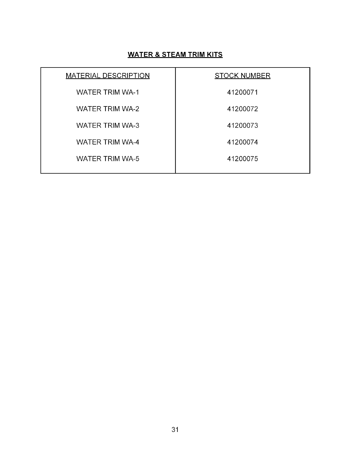
WATER &STEAM TRIM KITS
MATERIAL DESCRIPTION
WATER TRIM WA-1
WATER TRIM WA-2
WATER TRIM WA-3
WATER TRIM WA-4
WATER TRIM WA-5
STOCK NUMBER
41200071
41200072
41200073
41200074
41200075
31

14683004 (Form 500) Rev. 3/May, 2003
