DUNKIRK Boiler Manual L0611475
User Manual: DUNKIRK DUNKIRK Boiler Manual DUNKIRK Boiler Owner's Manual, DUNKIRK Boiler installation guides
Open the PDF directly: View PDF ![]() .
.
Page Count: 42
EV SERIES CAST IRON PRESSURE-FIRED
WET BASE HOT WATER BOILERS
DUNKIRK BOILERS
85 Middle Rd.
Dunkirk, NY 14048
www. ecrinternationaL com
P/N# 14683010, Rev. 3.1 [09/05] •Printed in USA. Made In USA
Boiler Ratings and Capacities ............................. 4
Rules for Safe Installation and Operation ............ 8
Indoor Boiler Installation .................................... 10
Jacket Assembly (Indoor Boilers) ...................... 11
System Piping (Indoor Boilers) .......................... 12
Weatherproof (Outdoor) Boiler Installation ........ 23
Normal Sequence of Operation ......................... 30
Lighting Instructions for Gas Burners ................ 30
Typical Vent Safety Switch Installation .............. 32
Maintenance ...................................................... 34
Service Hints and Troubleshooting .................... 36
Repair Parts ...................................................... 37
KEEP THIS MANUAL NEAR BOILER
BETA!N EOB EUTUBE BBEEBENCE J
The following defined symbols are used throughout
this manual to notify the reader of potential hazards
of varying risk levels.
ndJcates a potential hazardous situation J
hJch, if not avoided, MAY result in minor orJ
oderate injury. It may also be used to alert J
gainst unsafe practices. 3
cMoPORTANT: Read the following instructions'%}
MPLETELY before insta!!ingH j
/9""ii7", '
',4:dy,,
C.S.A. Certified
For Natural Gas Or Propane
¢@@
Tested For 100 LBS
ASME
Working Pressure
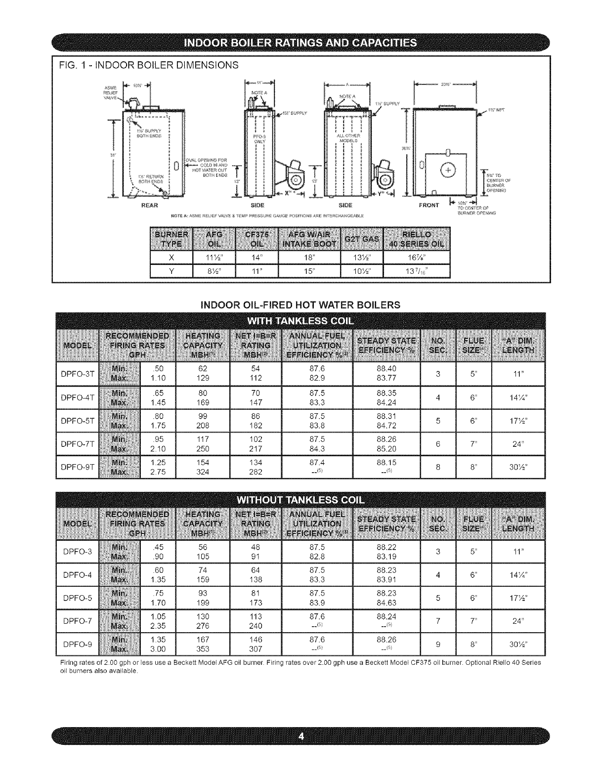
FIG, 1 - INDOOR BOILER DIMENSIONS
L
i 0
REA_
±
81DE 5_OE
INDOOR OIL-FIRED HOT WATER BOILERS
62 54 87.6 88.40
DPFO-3T 129 I12 82.9 83.77 I1"
80 70 87.5 88.35
DPFO-4T 14_A''
169 I47 83.3 84.24
99 86 87.5 88.31
DPFO-5T 17½"
208 I82 83.8 84.72
117 I02 87.5 88.26
DPFO-7T 24"
250 217 84.3 85.20
154 134 87.4 88.15
DPFO-9T 30½"
324 282 __5) __(5)
DPFO-3 .45 56 48 87.5 88.22 5" I1"
.90 105 91 82.8 83.19
DPFO-4 1.605 74 64 87.5 88.23
159 I38 83.3 83.91 6" 14_A"
DPFO-5 I!#0 93 81 87.5 88.23 6" 17½"
199 I73 83.9 84.63
DPFO-7 1.05 130 I13 87.6 88.24 7" 24"
2.35 276 240 __(5) __(5)
1.35 167 I46 87.6 88.26
DPFO-9 3.00 353 307 __(5) __(5) 8" 30½"
Firing rates of 2.00 gph or less use a Beckett Model AFG oil burner Firing rates over 2.00 gph use a Beckett Model CF375 oil burner. Optional Riello 40 Series
oil burners also available.
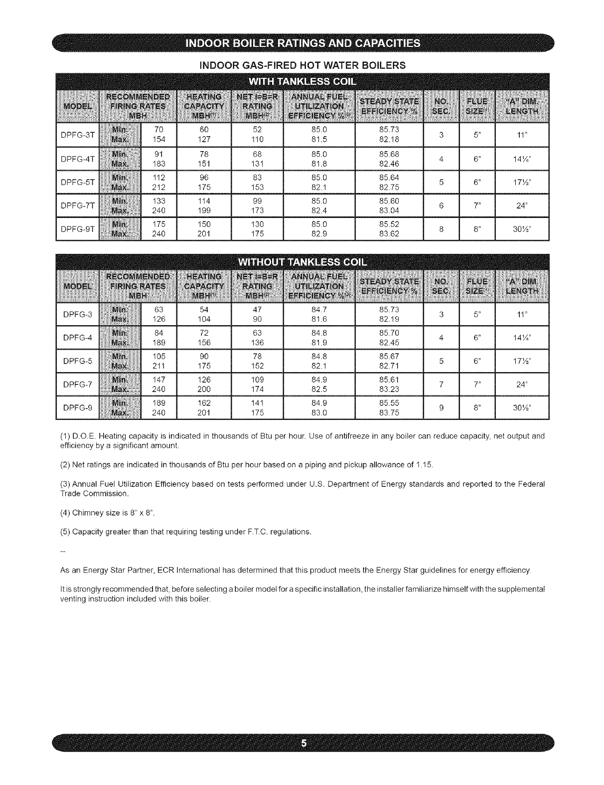
iNDOOR GAS-FIRED HOT WATER BOILERS
70 60 52 85.0 85.73
DPFG-3T 11"
I54 127 110 81.5 82.18
91 78 68 85.0 85.68
DPFG-4T 14¼"
I83 151 131 81.8 82.46
I12 96 83 85.0 85.64
DPFG-5T 17½"
212 175 153 82.1 82.75
I33 114 99 85.0 85.60
DPFG-7T 24"
240 199 173 82.4 83.04
I75 150 130 85.0 85.52
DPFG-9T 30½"
240 201 175 82.9 83.62
63 54 47 84.7 85.73
DPFG-3 3 5" 11"
I26 104 90 81.6 82.19
84 72 63 84.8 85.70
DPFG-4 4 6" 14¼"
I89 156 136 81.9 82.45
105 90 78 84.8 85.67
DPFG-5 5 6" 17½"
211 175 152 82.1 82.7I
I47 128 109 84.9 85.61
DPFG-7 240 200 174 82.5 83.23 7 7" 24"
189 162 141 84.9 85.55
DPFG-9 9 8" 30½"
240 201 175 83.0 83.75
(1) D.O.E. Heating capacity is indicated in thousands of Btu per hour. Use of antifreeze in any boiler can reduce capacity, net output and
efficiency by a significant amount.
(2) Net ratings are indicated in thousands of Btu per hour based on a piping and pickup allowance of 1.15.
(3) Annual Fuel Utilization Efficiency based on tests performed under U.S. Department of Energy standards and reported to the Federal
Trade Commission.
(4) Chimney size is 8" x 8".
(5) Capacity greater than that requiring testing under F.T.C. regulations.
As an Energy Star Partner, ECR International has determined that this product meets the Energy Star guidelines for energy efficiency.
It is strongly recommended that, before selecting a boiler model for a specific installation, the installer familiarize himself with the supplemental
venting instruction included with this boiler.
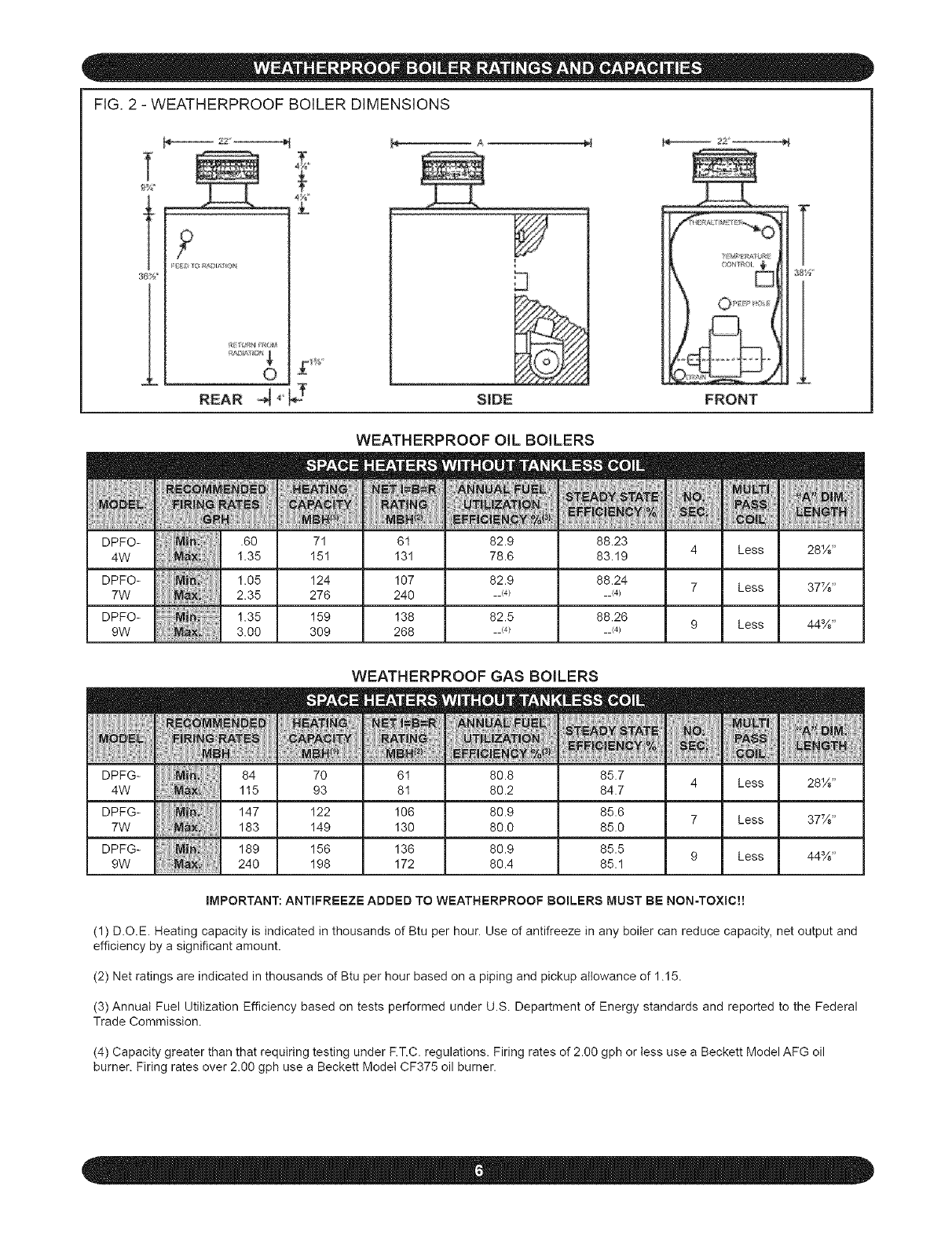
FIG, 2 - WEATHERPROOF BOILER DIMENSIONS
T
t
L
2Z_
?
REAR _ _'_ SIDE FRONT
T
38Y_
l
DPFO-
4W
DPFO-
7W
DPFO-
9W
DPFG-
4W
WEATHERPROOF OIL BOILERS
.60 71 61 82.9 88.23
1.35 I51 I31 78.6 83.19
1.05 I24 I07 82.9 88.24
2.35 276 240 __(4) __<4)
1.35 159 138 82.5 88.26
3.00 309 268 __(4) __<4)
m
NO.
_EC.
4
7
9
DPFG-
7W
DPFG-
9W
WEATHERPROOF GAS BOILERS
70 61 80.8 85.7
93 81 80.2 84.7
I22 I06 80.9 85.6
I49 I30 80.0 85.0
I56 I36 80.9 85.5
I98 I72 80.4 85.1
m
NO,
4
7
9
m
'MULTI:
PASS1
,6:O1_i
Less
Less
Less
28½"
37½"
44%"
iMPORTANT: ANTIFREEZE ADDED TO WEATHERPROOF BOILERS MUST BE NON-TOXIC!!
(1) D.O.E Heating capacity is indicated in thousands of Btu per hour. Use of antifreeze in any boiler can reduce capacity, net output and
efficiency by a significant amount.
(2) Net ratings are indicated in thousands of Btu per hour based on a piping and pickup allowance of 1.15.
(3) Annual Fuel Utilization Efficiency based on tests performed under U.S. Department of Energy standards and reported to the Federal
Trade Commission.
(4) Capacity greater than that requiring testing under F.T.C. regulations. Firing rates of 2.00 gph or tess use a Beckett Model AFG oil
burner. Firing rates over 2.00 gph use a Beckett Model CF375 oil burner.
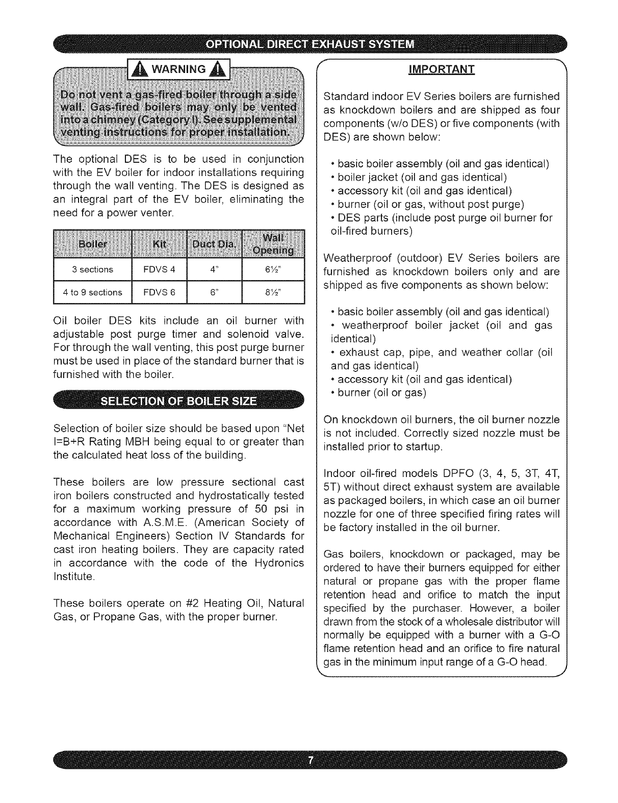
The optional DES is to be used in conjunction
with the EV boiler for indoor installations requiring
through the wall venting, The DES is designed as
an integral part of the EV boiler, eliminating the
need for a power venter.
_iiiiii_iii_i_iiiIHi_iiiiiijiiii_i_iiii_i1iii_i_iiiIiii_iiiiit_iiiiii_i_iiii_i_i_iii!iiI_i_!iiii!!iiii1iii
3 sections FDVS 4 4" 6W'
4 to 9 sections FDVS 6 6" 8½"
Oil boiler DES kits include an oil burner with
adjustable post purge timer and solenoid valve.
For through the wall venting, this post purge burner
must be used in place of the standard burner that is
furnished with the boiler.
Selection of boiler size should be based upon "Net
I=B+R Rating MBH being equal to or greater than
the calculated heat loss of the building.
These boilers are low pressure sectional cast
iron boilers constructed and hydrostatically tested
for a maximum working pressure of 50 psi in
accordance with A.S.M.E. (American Society of
Mechanical Engineers) Section IV Standards for
cast iron heating boilers. They are capacity rated
in accordance with the code of the Hydronics
Institute.
These boilers operate on #2 Heating Oil, Natural
Gas, or Propane Gas, with the proper burner.
IMPORTANT
Standard indoor EV Series boilers are furnished
as knockdown boilers and are shipped as four
components (w/o DES) or five components (with
DES) are shown below:
• basic boiler assembly (oil and gas identical)
• boiler jacket (oil and gas identical)
• accessory kit (oil and gas identical)
• burner (oil or gas, without post purge)
• DES parts (include post purge oil burner for
oil-fired burners)
Weatherproof (outdoor) EV Series boilers are
furnished as knockdown boilers only and are
shipped as five components as shown below:
• basic boiler assembly (oil and gas identical)
• weatherproof boiler jacket (oil and gas
identical)
• exhaust cap, pipe, and weather collar (oil
and gas identical)
• accessory kit (oil and gas identical)
• burner (oil or gas)
On knockdown oil burners, the oil burner nozzle
is not included. Correctly sized nozzle must be
installed prior to startup.
Indoor oil-fired models DPFO (3, 4, 5, 3T, 4T,
5T) without direct exhaust system are available
as packaged boilers, in which case an oil burner
nozzle for one of three specified firing rates wilt
be factory installed in the oil burner.
Gas boilers, knockdown or packaged, may be
ordered to have their burners equipped for either
natural or propane gas with the proper flame
retention head and orifice to match the input
specified by the purchaser. However, a boiler
drawn from the stock of a wholesale distributor will
normally be equipped with a burner with a G-O
flame retention head and an orifice to fire natural
as in the minimum input range of a G-O head. ,J
• Read the installation manual before beginning
the installation. Failure to follow the rules for
safe operation and the instructions can cause a
malfunction of the boiler and result, serious bodily
injury, and/or property damage.
• Check your local codes and utility requirements
before installation. The installation must be in
accordance with their directives, or, in their absence,
follow NFPA Installation Codes and good industry
practice.
• Before servicing, allow boiler to coot. Always shut
off any electricity and oil to boiler when working on
it. This will prevent any electrical shocks or burns.
• Inspect oil lines and connections for leaks.
• Be certain oil burner nozzle or gas orifice is size
required. Over-firing will result in early failure of
the boiler sections. This will cause dangerous
operation.
• Never vent this boiler into an enclosed space.
Always vent to the outside. Never vent to another
room or inside a building.
• Be sure there is adequate air supply for complete
combustion.
• Follow a regular service and maintenance
schedule for efficient and safe operation.
• Keep boiler area clean and free of combustible
material, gasoline, and other flammable vapors
and liquids.
• Proper through-the-walt venting requires use of
complete DES (oil-fired units only).
• Oil and gas burners are not do-it-yourself items.
This boiler must be installed and serviced by
qualified professionals using combustion test
instruments.
• Be aware when piping the relief valve if the
system pressure exceeds the safe limit of 30 Ibs.
per square inch, the relief valve will automatically
open. Lifting of the relief valve can discharge large
quantities of steam and hot water, which may
damage the surroundings. Before installing the
relief valve, read the manufacturer's instructions
and the maintenance section of the manual on
relief valves.
•Frequent and mysterious lifting of the relief valve
may be a sign of an improperly sized expansion
tank. Installation and sizing of the expansion tank
must consider the heating system's total water
volume, temperature, boiler initial fill pressure, and
system arrangement. For proper installation and
maintenance follow the guidelines established by
ECR and the manufacturer.
•Expansion tank performance and life expectancy
can be hindered by overfilling the boiler. ECR
recommends an initial fill pressure of 10 - 12 psig.
For higher fill pressures, the expansion tank's air
charge will need to match the fill pressure. Consult
the manufacturer's guidelines for sizing and
selection.
•Purging the heating system of air and gases
during the boiler's initial commissioning is critical
for proper circulation and quiet performance. Once
the air and gases are purged, for boiler installations
using float type vents, the air vents should be closed
for normal operation. If air is heard or noticed by a
loss of heat, purge the system and open the vents
for a short period of time.
-iAc o ,o.Ai
This boiler has been designed for residential
installations. If used for commercial applications,
all jurisdictional requirements must be met. This
may require wiring and/or piping modifications.
The manufacturer is not responsible for any
changes to the original design.
DO NOT USE GASOLINE CRANKCASE
DRAININGS OR ANY OIL CONTAINING
k..GASOLINE"
Check to be sure you have the right size boiler
before starting the installation. See rating and
capacity tables on preceding pages. Check the
rating plate on the right side of the boiler.
You must see that the boiler is supplied with the
proper fuel, fresh air for combustion, and a suitable
electrical supply. Also, the boiler must be connected
to a suitable venting system and an adequate piping
system. Finally, a thermostat, properly located, is
needed for control of the heating system. If you
have any doubts as to the various requirements,
check with local authorities and obtain professional
help where needed.
These installation instructions are vital to the proper
and safe operation of the heating system. Take the
time to be sure they are carefully followed.
lways keep the manual fuel supply valve shut I
if the burner is shut down for an extended r
eriod of time. J
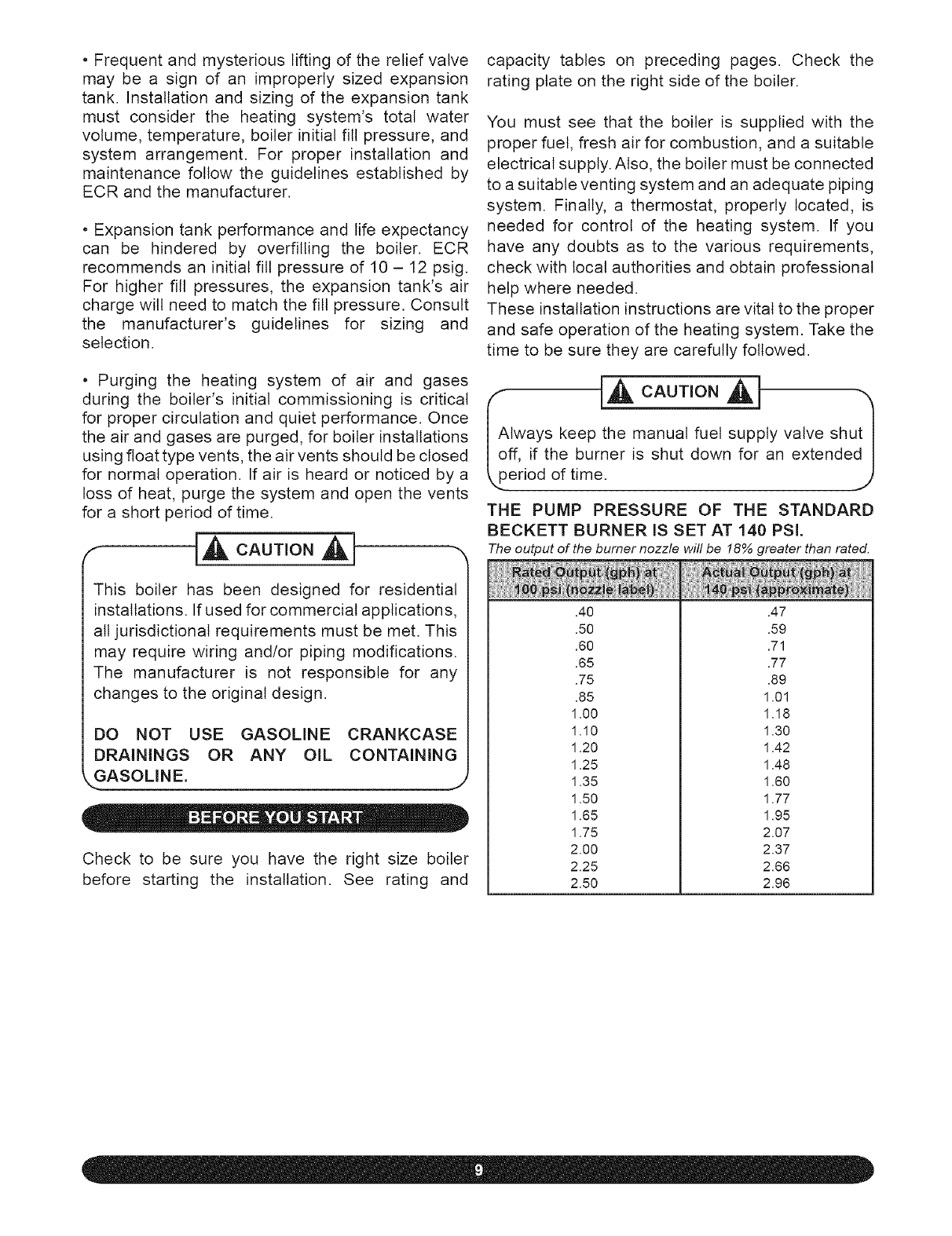
THE PUMP PRESSURE OF THE STANDARD
BECKETT BURNER IS SET AT 140 PSI.
The output of the burner nozzle will be 18% greater than rated.
.40
.50
.60
.65
.75
.85
1.00
1.10
1.20
1.25
1.35
1.50
1.65
1.75
2.00
2.25
2.50
.47
.59
.71
.77
.89
1.01
1.18
1.30
1.42
1.48
1.60
1.77
1.95
2.07
2.37
2.66
2.96
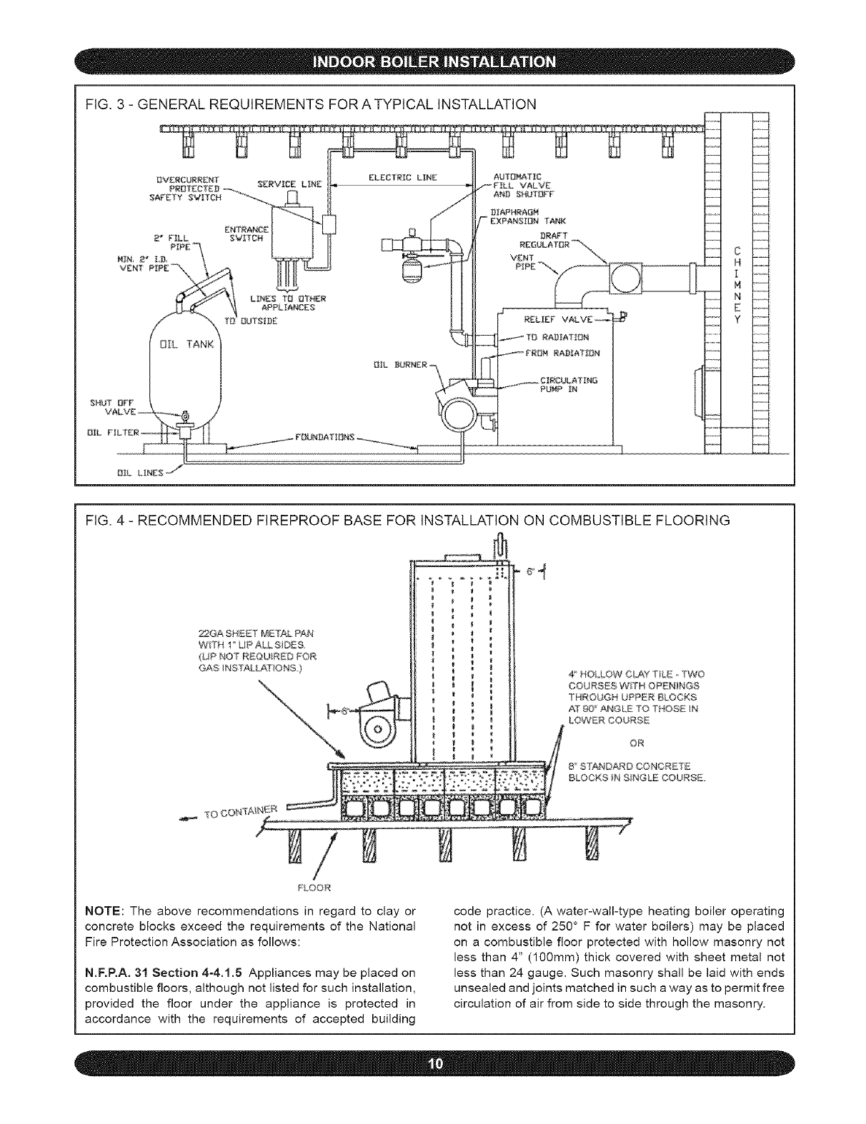
FIG. 3 - GENERAL REQUIREMENTS FOR ATYPICAL INSTALLATION
k.....
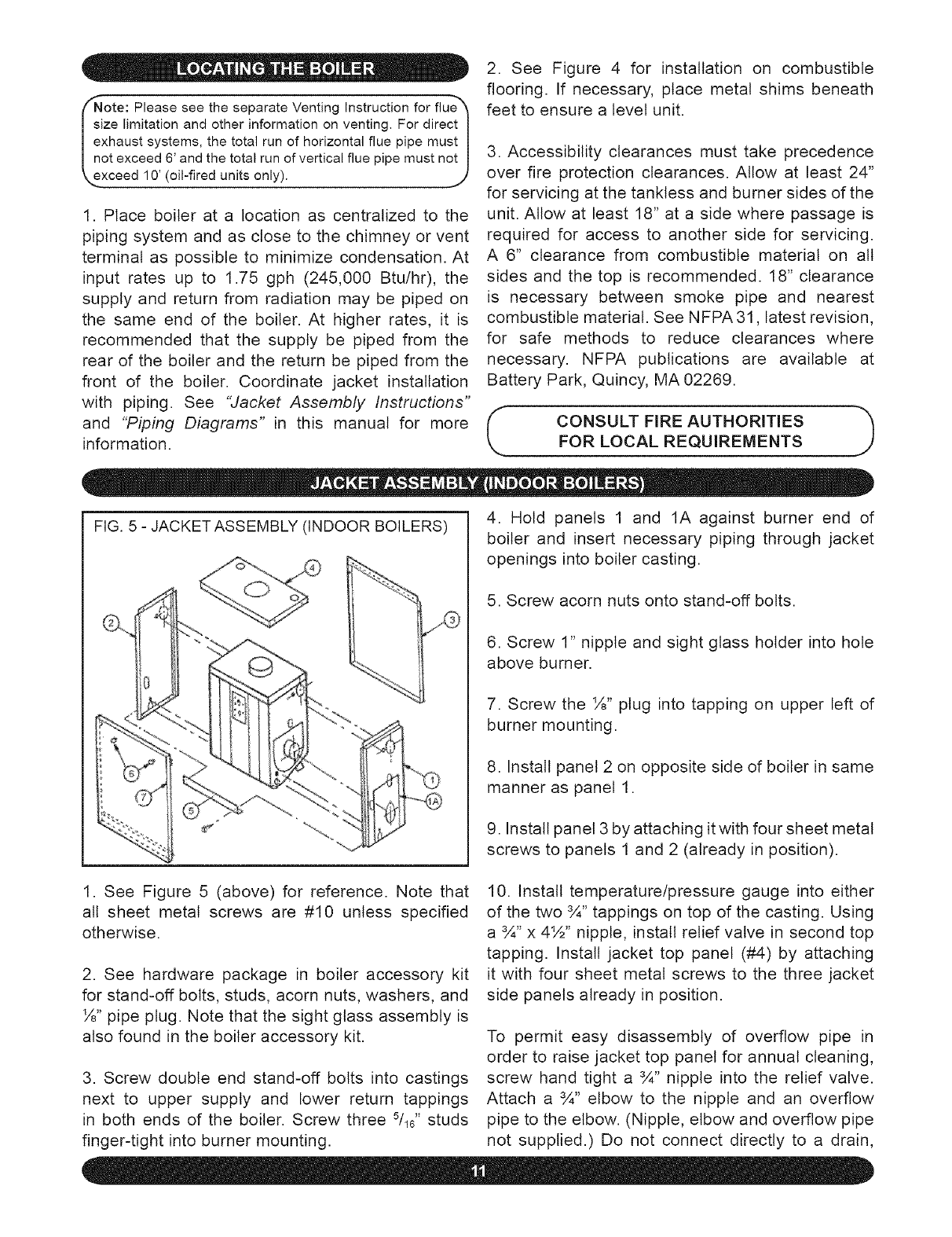
FIG. 4 - RECOMMENDED FIREPROOF BASE FOR INSTALLATION ON COMBUSTIBLE FLOORING
2"2GASHBET METAL PAN
WTH I LIPAU.SiDES
(LIP NOT R_QU_R_D POR
GAS _NS_ALL#_I"ONS )
|
4" HOLLOW C_<f T_LE _ TWO
COURSES WTH OPENINGS
THROUGH 8PPER BLOCKS
AT 9Q _ ANGLE TO THOS_ IN
LOW£R COURS_
OR
8" BTANDAR@ C©NCRET_
BLOCKS N B_NGLE COURSE
/
FLOOR
NOTE: The above recommendations in regard to clay or
concrete blocks exceed the requirements of the National
Fire Protection Association as follows:
N.F.RA. 31 Section 4-4.1.5 Appliances may be placed on
combustible floors, although not listed for such installation,
provided the floor under the appliance is protected in
accordance with the requirements of accepted building
code practice. (A water-wall-type heating boiler operating
not in excess of 250 ° F for water boilers) may be placed
on a combustible floor protected with hollow masonry not
less than 4" (100mm) thick covered with sheet metal not
less than 24 gauge. Such masonry shall be laid with ends
unsealed and joints matched in such a way as to permit free
circulation of air from side to side through the masonry.
ote:PleaseseetheseparateVentingInstructionforflue%I
zelimitationandotherinformationonventing.FordirectI
xhaustsystems,thetotalrunofhorizontalfluepipemustJ
otexceed6'andthetotalrunofverticalfluepipemustnotJ
xceed10'(oil-firedunitsonly), j
1. Place boiler at a location as centralized to the
piping system and as close to the chimney or vent
terminal as possible to minimize condensation. At
input rates up to 1.75 gph (245,000 Btu/hr), the
supply and return from radiation may be piped on
the same end of the boiler. At higher rates, it is
recommended that the supply be piped from the
rear of the boiler and the return be piped from the
front of the boiler. Coordinate jacket installation
with piping. See "Jacket Assembly Instructions"
and "Piping Diagrams" in this manual for more
information.
2. See Figure 4 for installation on combustible
flooring. If necessary, place metal shims beneath
feet to ensure a level unit.
3. Accessibility clearances must take precedence
over fire protection clearances. Allow at least 24"
for servicing at the tankless and burner sides of the
unit. Allow at least 18" at a side where passage is
required for access to another side for servicing.
A 6" clearance from combustible material on all
sides and the top is recommended. 18" clearance
is necessary between smoke pipe and nearest
combustible material. See NFPA 31, latest revision,
for safe methods to reduce clearances where
necessary. NFPA publications are available at
Battery Park, Quincy, MA 02269.
CONSULT FIRE AUTHORITIES J
FOR LOCAL REQUIREMENTS
FIG. 5 -JACKETASSEMBLY (INDOOR BOILERS) 4. Hold panels 1 and 1A against burner end of
boiler and insert necessary piping through jacket
openings into boiler casting.
5. Screw acorn nuts onto stand-off bolts.
6. Screw 1" nipple and sight glass holder into hole
above burner.
7. Screw the ½" plug into tapping on upper left of
burner mounting.
8. Install panel 2 on opposite side of boiler in same
manner as panel 1.
9. Install panel 3 by attaching it with four sheet metal
screws to panels 1 and 2 (already in position).
1. See Figure 5 (above) for reference. Note that
all sheet metal screws are #10 unless specified
otherwise.
2. See hardware package in boiler accessory kit
for stand-off bolts, studs, acorn nuts, washers, and
½" pipe plug. Note that the sight glass assembly is
also found in the boiler accessory kit.
3. Screw double end stand-off bolts into castings
next to upper supply and lower return tappings
in both ends of the boiler. Screw three Sll?' studs
finger-tight into burner mounting.
10. Install temperature/pressure gauge into either
of the two 3A" tappings on top of the casting. Using
a 3A" x 4½" nipple, install relief valve in second top
tapping. Install jacket top panel (#4) by attaching
it with four sheet metal screws to the three jacket
side panels already in position.
To permit easy disassembly of overflow pipe in
order to raise jacket top panel for annual cleaning,
screw hand tight a 3A" nipple into the relief valve.
Attach a 3A" elbow to the nipple and an overflow
pipe to the elbow. (Nipple, elbow and overflow pipe
not supplied.) Do not connect directly to a drain,
but leavean air gap. Noshutoffof anydescription
shallbe placedbetweenthe safetyreliefvalveand
the boiler, or on discharge pipes betweensuch
safety valves and the atmosphere.Installationof
the safety relief valve shall conformto the ANSI/
ASME Boilerand PressureVesselCode, Section
IV. The manufactureris not responsiblefor any
waterdamage.
If preferred,one of the top tappingsmaybe used
for an airventandthe reliefvalvemaybeinstalled
in an upper 1½" side tappingof the castingwith
a bushing,nipple,and streetelbow.Valvespindle
mustbevertical.
11. Installangle iron (#5)open edgeup to panels
1 and 2 on the remainingexposedside of the
boilernear floor level.Angle iron is attachedwith
two sheetmetalscrewsto the insideof the turned
edgesof panels1 and2.
12. Install knobs (#6) on door panel (#7) using #8
machine screws. Install door panel by resting lower
edge inside angle iron (#5) and snapping top sides
into place.
1. Antifreeze added to boilers must be non-toxic,
and must of a type specifically intended for use
in closed hydronic heating systems. Under no
circumstances should automotive antifreeze be
used.
2. Use of antifreeze in any boiler may reduce
capacity by 10% or more and increase fuel
consumption. Tanktess coil performance will fall as
concentration of antifreeze is increased. See below
for water volumes of boilers and piping.
3. Because antifreeze forms slush rather than hard
ice, it is safe to protect only to 10 degrees above
coldest temperature anticipated provided slush
formed can move towards expansion tank.
BOILER WATER VOLUMES
DPF-3 7 DPF-3T 10
DPF-4 9 DPF-4T 12
DPF-5 11 DPF-5T 14
DPF-7 15 DPF-6T 16
DPF-9 19 DPF-8T 20
PiPiNG WATER VOLUMES
Divide total length of piping in feet by appropriate factor
below to determine volume in gallons.
½" 82.5 63.5
¾" 40.0 36.0
1" 23.3 22.2
1%" 15.3 12.8
1½" 10.8 9.5
2" 6.2 5.8
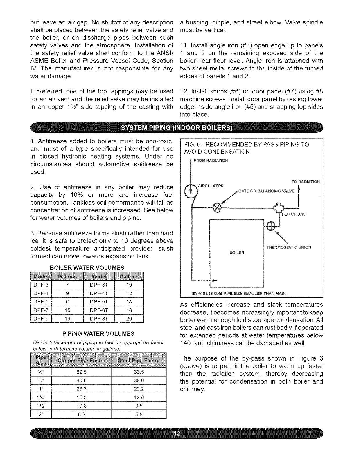
FIG. 6 - RECOMMENDED BY-PASS PIPING TO
AVOID CONDENSATION
FROM RADiATiON
(?O RADIATION
TNERMOSTA, T_C UNION
BO_LER
BYPA@8 IS ONE P_PE @IZE @_IALLER THAN MA_N
As efficiencies increase and slack temperatures
decrease, it becomes increasingly important to keep
boiler warm enough to discourage condensation. All
steel and cast-iron boilers can rust badly if operated
for extended periods at water temperatures below
140 and chimneys can be damaged as well.
The purpose of the by-pass shown in Figure 6
(above) is to permit the boiler to warm up faster
than the radiation system, thereby decreasing
the potential for condensation in both boiler and
chimney.
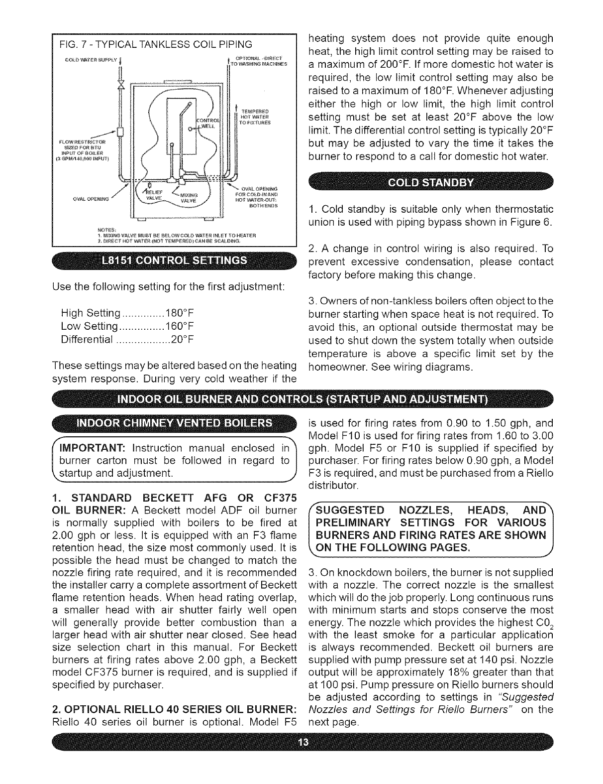
FIG.7-TYPICALTANKLESSCOILPIPING
II
Use the following setting for the first adjustment:
High Setting .............. 180°F
Low Setting ............... 160°F
Differential .................. 20°F
These settings may be altered based on the heating
system response. During very cold weather if the
heating system does not provide quite enough
heat, the high limit control setting may be raised to
a maximum of 200°F. If more domestic hot water is
required, the low limit control setting may also be
raised to a maximum of 180°F. Whenever adjusting
either the high or low limit, the high limit control
setting must be set at least 20°F above the low
limit. The differential control setting is typically 20°F
but may be adjusted to vary the time it takes the
burner to respond to a call for domestic hot water.
1. Cold standby is suitable only when thermostatic
union is used with piping bypass shown in Figure 6.
2. A change in control wiring is also required. To
prevent excessive condensation, please contact
factory before making this change.
3. Owners of non-tanktess boilers often object to the
burner starting when space heat is not required. To
avoid this, an optional outside thermostat may be
used to shut down the system totally when outside
temperature is above a specific limit set by the
homeowner. See wiring diagrams.
_sb,MPORTANT: Instruction manual enclosed i!_
umer carton must be followed in regard t
tartup and adjustment.
1. STANDARD BECKETT AFG OR CF375
OIL BURNER: A Beckett model ADF oil burner
is normally supplied with boilers to be fired at
2.00 gph or less. It is equipped with an F3 flame
retention head, the size most commonly used. It is
possible the head must be changed to match the
nozzle firing rate required, and it is recommended
the installer carry a complete assortment of Beckett
flame retention heads. When head rating overlap,
a smaller head with air shutter fairly well open
will generally provide better combustion than a
larger head with air shutter near closed. See head
size selection chart in this manual. For Beckett
burners at firing rates above 2.00 gph, a Beckett
model CF375 burner is required, and is supplied if
specified by purchaser.
2. OPTIONAL RIELLO 40 SERIES OIL BURNER:
Riello 40 series oil burner is optional. Model F5
is used for firing rates from 0.90 to 1.50 gph, and
Model F10 is used for firing rates from 1.60 to 3.00
gph. Model F5 or F10 is supplied if specified by
purchaser. For firing rates below 0.90 gph, a Model
F3 is required, and must be purchased from a Rietto
distributor.
/'-SUGGESTED NOZZLES, HEADS, AN D"_
PRELIMINARY SETTINGS FOR VARIOUS I
BURNERS AND FIRING RATES ARE SHOWN I
,..ON THE FOLLOWING PAGES. J
3. On knockdown boilers, the burner is not supplied
with a nozzle. The correct nozzle is the smallest
which will do the job properly. Long continuous runs
with minimum starts and stops conserve the most
energy. The nozzle which provides the highest C0_
with the least smoke for a particular application
is always recommended. Beckett oil burners are
supplied with pump pressure set at 140 psi. Nozzle
output will be approximately 18% greater than that
at 100 psi. Pump pressure on Rietto burners should
be adjusted according to settings in "Suggested
Nozzles and Settings for Riello Burners" on the
next page.
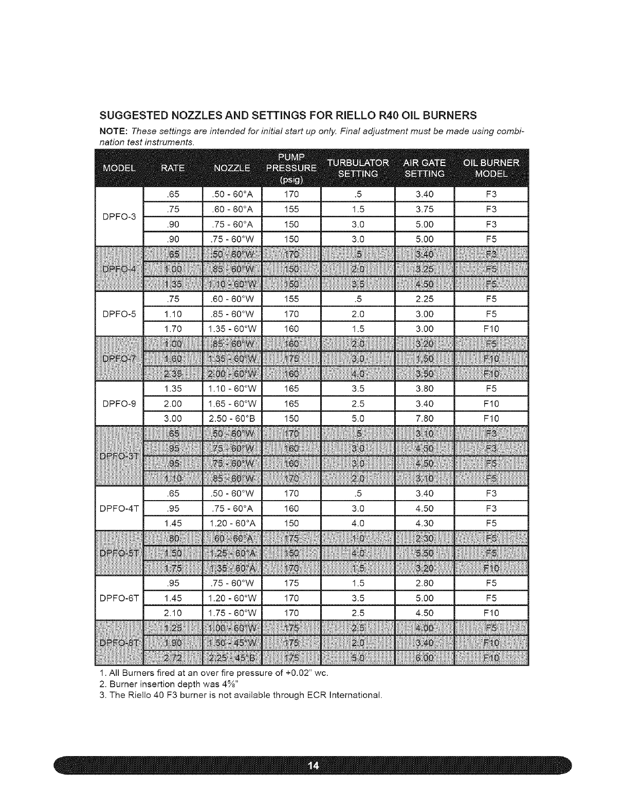
SUGGESTED NOZZLES AND SETTINGS FOR RIELLO R40 ONL BURNERS
NOTE: These settings are intended for initial start up only. Final adjustment must be made using combi-
nation test instruments.
mm.65
.75
DPFO-3 .90
.90
.75
DPFO-5 1.10
1.70
1.35
DPFO-9 2.00
3.00
.65
DPFO-4T .95
1.45
.95
DPFO-6T 1.45
2.10
m
.50 - 60°A
.60 - 60°A
.75 - 60°A
.75 - 60°W
m
170
155
150
150
m
3.40
3.75
5.00
5.00
m
F3
F3
F3
F5
.60 - 60°W 155 .5 2.25 F5
.85 - 60°W 170 2.0 3.00 F5
1.35 - 60°W 160 1.5 3.00 F10
1.10 - 60°W 165 3.5 3.80 F5
1.65 - 60°W 165 2.5 3.40 F10
2.50 - 60°B 150 5.0 7.80 F10
.50 - 60°W 170 .5 3.40 F3
.75 - 60°A 160 3.0 4.50 F3
1.20 - 60°A 150 4.0 4.30 F5
.75 - 60°W 175 1.5 2.80 F5
1.20 - 60°W 170 3.5 5.00 F5
1.75 - 60°W 170 2.5 4.50 F10
1. All Burners fired at an over fire pressure of +0.02" wc.
2. Burner insertion depth was 4%"
3. The Riello 40 F3 burner is not available through ECR International.
o low a firing rate can cause excessive I
ondensation within the boiler and chimney I
sutting in severe rust and corrosion. A piping by- I
ass is recommended to minimize this problem:j)
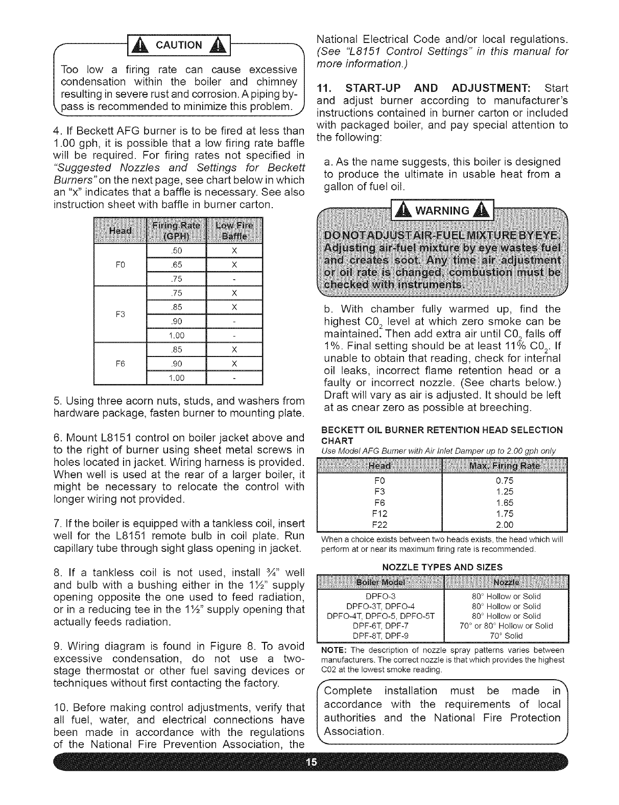
4. If Beckett AFG burner is to be fired at bess than
1.00 gph, it is possible that a low firing rate baffle
will be required. For firing rates not specified in
"Suggested Nozzles and Settings for Beckett
Burners'on the next page, see chart below in which
an "x" indicates that a baffle is necessary. See also
instruction sheet with baffle in burner carton.
F0
F3
F6
.5O X
.65 X
.75
.75 X
.85 X
.90
1.00
.85 X
.90 X
1.00
5. Using three acorn nuts, studs, and washers from
hardware package, fasten burner to mounting plate.
6. Mount L8151 control on boiler jacket above and
to the right of burner using sheet metal screws in
holes located in jacket. Wiring harness is provided.
When well is used at the rear of a larger boiler, it
might be necessary to relocate the control with
longer wiring not provided.
7. If the boiler is equipped with a tanktess coil, insert
well for the L8151 remote bulb in coil plate. Run
capillary tube through sight glass opening in jacket.
8. If a tanktess coil is not used, install 3A" well
and bulb with a bushing either in the 1½" supply
opening opposite the one used to feed radiation,
or in a reducing tee in the 1½" supply opening that
actually feeds radiation.
9. Wiring diagram is found in Figure 8. To avoid
excessive condensation, do not use a two-
stage thermostat or other fuel saving devices or
techniques without first contacting the factory.
10. Before making control adjustments, verify that
all fuel, water, and electrical connections have
been made in accordance with the regulations
of the National Fire Prevention Association, the
National Electrical Code and/or local regulations.
(See "L8151 Control Settings" in this manual for
more information.)
11. START-UP AND ADJUSTMENT: Start
and adjust burner according to manufacturer's
instructions contained in burner carton or included
with packaged boiler, and pay special attention to
the following:
a. As the name suggests, this boiler is designed
to produce the ultimate in usable heat from a
gallon of fuel oil.
b. With chamber fully warmed up, find the
highest C02 level at which zero smoke can be
maintained. Then add extra air until C02 falls off
1%. Final setting should be at least 11% C02. If
unable to obtain that reading, check for internal
oil leaks, incorrect flame retention head or a
faulty or incorrect nozzle. (See charts below.)
Draft will vary as air is adjusted. It should be left
at as cnear zero as possible at breeching.
BECKETT OIL BURNER RETENTION HEAD SELECTION
CHART
UseModel AFG Burner withAir Inlet Damper up to 2.00gph only
F0
F3
F6
F12
F22
0.75
1.25
1.65
1.75
2.00
When a choice exists between two heads exists, the head which will
perform at or near its maximum firing rate is recommended.
NOZZLE TYPES AND SIZES
DPFO-3
DPFO-3T, DPFO-4
DPFO-4T, DPFO-5, DPFO-5T
DPF-6T, DPF-7
DPF-8T, DPF-9
80 ° Hollow or Solid
80 ° Hollow or Solid
80 ° Hollow or Solid
70 ° or 80 ° Hollow or Solid
70 ° Solid
NOTE: The description of nozzle spray patterns varies between
manufacturers. The correct nozzle is that which provides the highest
C02 at the lowest smoke reading.
fComplete installation must be made in")
accordance with the requirements of Iocat I
authorities and the National Fire Protection I
/
.Association.
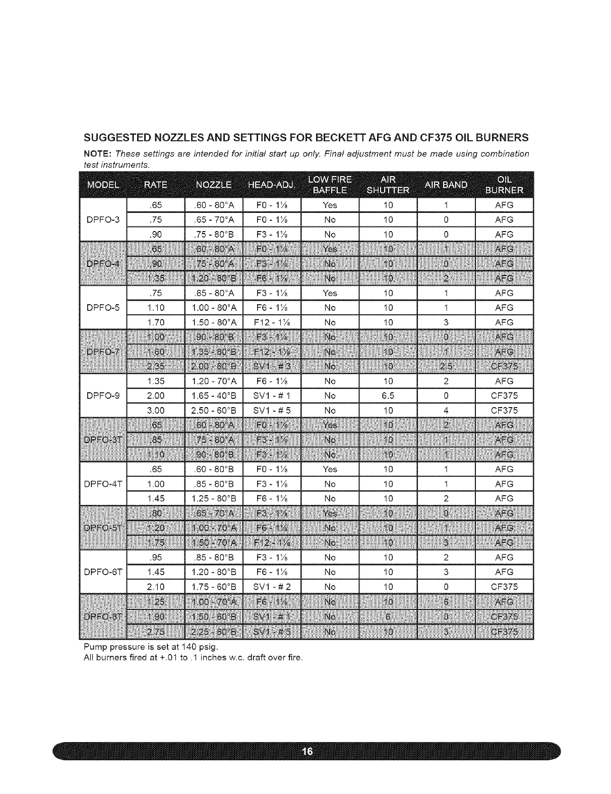
SUGGESTED NOZZLES AND SETTINGS FOR BECKETT AFG AND CF375 OIL BURNERS
NOTE: These settings are intended for initial start up only. Final adjustment must be made using combination
test instruments.
.65
DPFO-3 .75
.90
DPFO-5
DPFO-9
DPFO-4T
DPFO-6T
m
.60 - 80°A
.65 - 70°A
.75 - 80°B
.75 .65 - 80°A
1.10 1.00 - 80°A
1.70 1.50 - 80°A
1.35 1.20 - 70°A
2.00 1.65 - 40°B
3.00 2.50 - 60°B
.65 .60 - 80°B
1.00 .85 - 80°B
1.45 1.25 -80°B
.95 .85 - 80°B
1.45 1.20 - 80°B
2.10 1.75 -60°B
B
Yes
No
No
m
10
10
10
m
1
0
0
m
AFG
AFG
AFG
F3- I_A Yes 10 1 AFG
F6- I_A No 10 1 AFG
F12- I_A No 10 3 AFG
F6- 1_/8 No 10 2 AFG
SV1 - # 1 No 6.5 0 CF375
SV1 - # 5 No 10 4 CF375
F0 - 1_/8 Yes 10 1 AFG
F3- I_A No 10 1 AFG
F6- I_A No 10 2 AFG
F3- 1_/8 No 10 2 AFG
F6- 1_/8 No 10 3 AFG
SV1 - # 2 No 10 0 CF375
i i A@i
Pump pressure is set at 140 psig.
All burners fired at +.01 to .1 inches w.c. draft over fire.
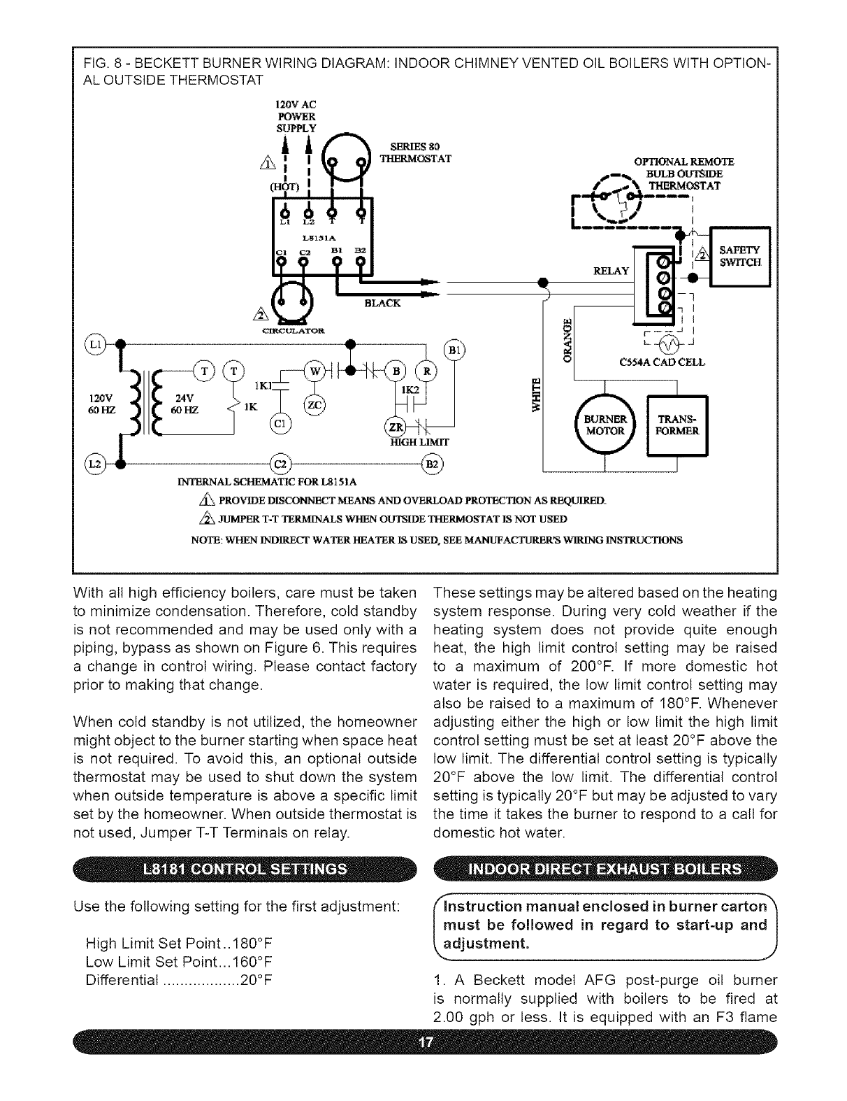
FIG. 8 - BECKETT BURNER WIRING DIAGRAM: INDOOR CHIMNEY VENTED OIL BOILERS WITH OPTION-
AL OUTSIDE THERMOSTAT
120V AC
POWER
SUPPLY
A_ 9 BLAC_
<_IgC_A'I'OR
HIGH LIMIT
INTERNAL SCHEMATIC FOR LS15]A
OPTIONAL REMOTE
.-. ,,u,J,OOT IDE
k....... _
RELAY
L J
C554A CAD CELL
Z_ PROVIDE DISCONNECT MEANS AND OVERLOAD PROTECTION AS REQUI_.
Z_ JUMPER T-T TERMINALS WHEN OUTSIDE THERMOSTAT IS NOT USED
NOTE: WHEN INDIRECT WATER HEATER IS USED, SEE MANUFACTURER'S WIRING INSTRUCTIONS
With all high efficiency boilers, care must be taken
to minimize condensation. Therefore, cold standby
is not recommended and may be used only with a
piping, bypass as shown on Figure 6. This requires
a change in control wiring. Please contact factory
prior to making that change.
When cold standby is not utilized, the homeowner
might object to the burner starting when space heat
is not required. To avoid this, an optional outside
thermostat may be used to shut down the system
when outside temperature is above a specific limit
set by the homeowner. When outside thermostat is
not used, Jumper T-T Terminals on relay.
These settings may be altered based on the heating
system response. During very cold weather if the
heating system does not provide quite enough
heat, the high limit control setting may be raised
to a maximum of 200°F. If more domestic hot
water is required, the low limit control setting may
also be raised to a maximum of 180°F. Whenever
adjusting either the high or low limit the high limit
control setting must be set at least 20°F above the
low limit. The differential control setting is typically
20°F above the low limit. The differential control
setting is typically 20°F but may be adjusted to vary
the time it takes the burner to respond to a call for
domestic hot water.
Use the following setting for the first adjustment:
High Limit Set Point..180°F
Low Limit Set Point... 160°F
Differential .................. 20°F
flnstruction manual enclosed in burner carton"_
must be followed in regard to start-up and I
t !: J
1. A Beckett model AFG post-purge oil burner
is normally supplied with boilers to be fired at
2.00 gph or less. It is equipped with an F3 flame
retention head, the size most commonly used. It is
possible the head must be changed to match the
nozzle firing rate required, and it is recommended
the installer carry a complete assortment of Beckett
flame retention heads. When head ratings overlap,
a smaller head with air shutter fairly well open wilt
generally provide better combustion than a larger
head with air shutter near closed.
2. At firing rates above 2.00 gph, a special Beckett
model CF375 burner must be used and is supplied
if specified by purchaser.
3. Post-purge oil burners are supplied with pump
pressure set at 140 psi. Nozzle output wilt be
approximately 18% grater than that at 100 psi.
4. The burner is not supplied with a nozzle. The
correct nozzle is the smallest which will do the
job properly. Long continuous runs with minimum
starts and stops conserve the most energy. The
nozzle which provides the highest C% with the
least smoke for a particular application is always
recommended.
A WARNING A
5. Using acorn nuts, studs, and washers from
hardware package, fasten burner to mounting plate.
Do not disturb chamber when inserting firing head.
6. Mount L8151 control on boiler jacket above and
to the right of burner using sheet metal screws in
holes located in jacket. Wiring harness is provided.
When welt is used at the rear of a larger boiler, it
might be necessary to relocate the control with
longer wiring not provided.
7. If boiler has a tanktess coil, insert well for the
L8151 remote bulb in coil plate. Run capillary tube
through sight glass opening in jacket.
8. If a tankless coil is not used, install 3A" welt
and bulb with a bushing either in the 1½" supply
opening opposite the one used to feed radiation,
or in a reducing tee in the 1½" supply opening that
feeds radiation.
9. Mount overfire pressure switch at upper right
of burner on screws already in jacket. Burner will
shut down if overfire pressure reaches .35" H20 due
to a plugged flue or high wind. See "Vent Safety
Switch Installation" in this installation and operation
manual for more information.
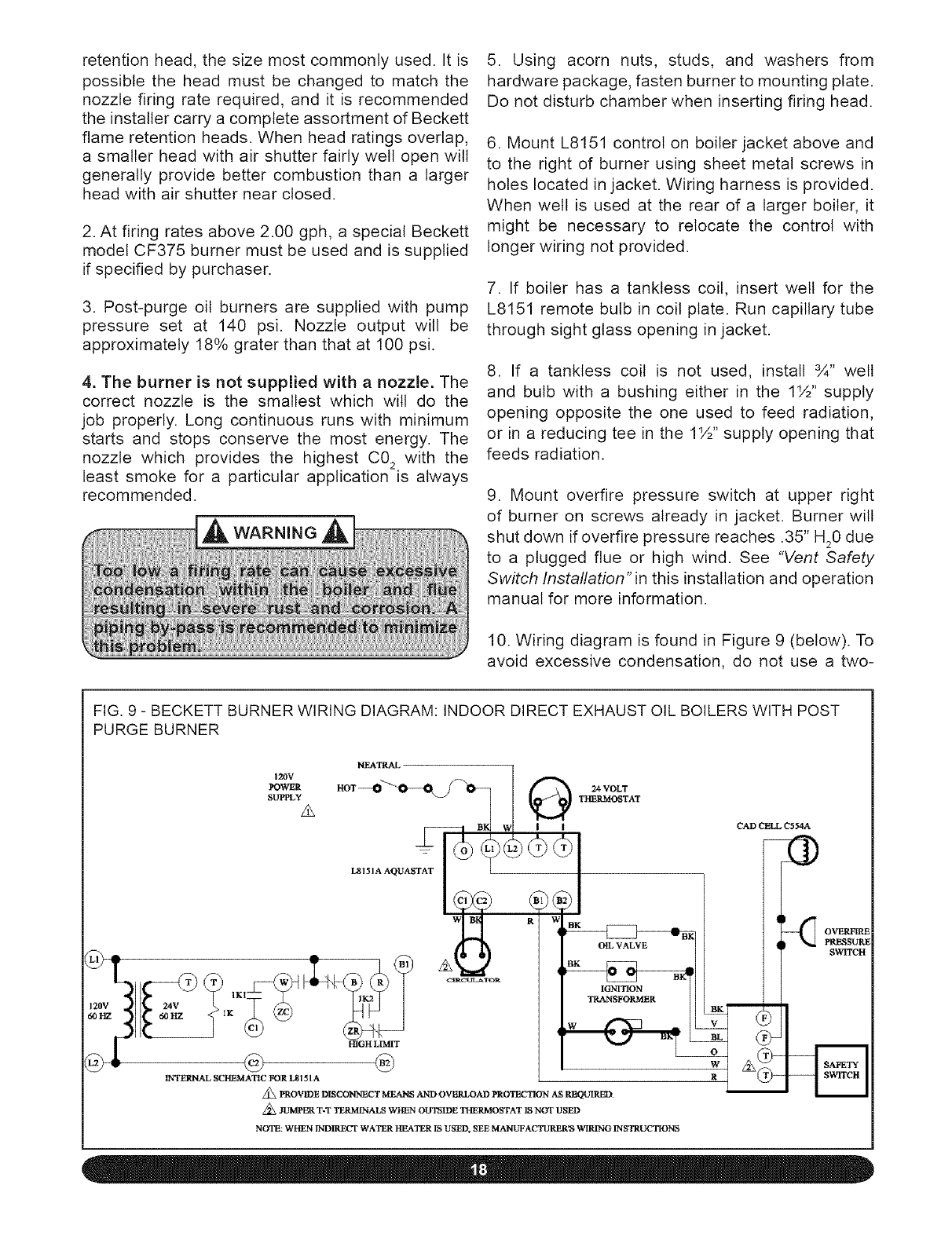
10. Wiring diagram is found in Figure 9 (below). To
avoid excessive condensation, do not use a two-
FIG. 9 - BECKETT BURNER WIRING DIAGRAM: INDOOR DIRECT EXHAUST OIL BOILERS WITH POST
PURGE BURNER
120V
!_OWER
SL1PPLY
HIGH LLMIT
INTERNAL SCHEMATIC FOR LSISIA
IGNITION
T_NSFORMER
Z_ PROVIDE DISCOHNECT MEAHS AND OVERLOAD PROTECTION AS REQUIRED
Z_ JUMPER T_T TERMFNALS WHEN OUTSIDE THERMOSTAT IS NOT USED
NOTE: WHEN INDIRECT WATER }[EATER IS USED, SEE MAIqL_ACTURER_ WIRING INSTRUCTIONS
CAD CELL C554A
OVERFIRE
PR_SS_t,E
SWITCH
BL
stage thermostat or other fuel saving devices or
techniques without first contacting the factory.
11. Install Gar-Ber filter as provided rather than a
standard filter between burner and oil storage tank.
12. Before making control adjustments, verify that
all fuel, water, and electrical connections have been
made in accordance with the regulations of the
National Fire Prevention Association, the National
Electrical Code, and/or local regulations.
13. STARTUPANDADJUSTMENT: Start and adjust
burner according to manufacturer's instructions
contained in burner carton or included with boiler
and pay special attention to the following:
a. As the name suggests, this boiler is designed
to produce the ultimate in usable heat from a
gallon of fuel oil.
b. With chamber fully warmed up, find the
highest CO 2 level at which zero Smoke can be
maintained. Then add extra air until CO 2falls off
1%. Final setting should be at least 11% CO 2. If
unable to obtain that reading, check for internal
oil leaks, incorrect flame retention head, or faulty
or incorrect nozzle.
14. POST PURGE TIMING: With through-the-wall
venting there is no overfire draft present after the
burner shuts down. Therefore a post purge must be
used to prevent the hot chamber from overheating
the nozzle.
The post purge timer is part of the Honeywell
intermittent primary control, which is located on the
Beckett oil burner. The post purge time has been
preset to 4 minutes but may be adjusted to 0, 2,
4, or 6 minutes by adjusting the switches on the
side of the intermittent primary control. With a stack
thermometer in place, the boiler fully warmed up
(200°F or more), and the boiler running, turn the
high limit control on the aquastat all the way down.
The burner motor should then be running with the
flame off (i.e., in post purge). Measure the time it
takes from the flame off until the stack temperature
falls to the same temperature as the boiler water.
Adjust the post purge timer to nearest time interval,
always rounding up if possible. For example, if the
time measured is 3 minutes and 20 seconds, then
set the post purge timer at 4 minutes.
Whenever the nozzle is removed for service, check
for varnish forming on the outside of the nozzle. If
carbon and varnish do not wipe off easily, increase
the post purge time.
15. LIMITED RECYCLEAND LIMITED RESET: The
Honeywell R7184P1031 interrupted-duty primary
control utilizes two safety features to protect the
boiler from being saturated with oil. Limited recycle
will allow the burner 3 attempts to ignite, if ignition
is unproven the control locks out. The control's
reset button can then be pressed. The limited reset
feature will allow the burner to be reset 3 times
before it locks out. To unlock the control requires
the reset button to be held for 30 seconds.
16. ELECTRICAL WIRING: Wiring should conform
with the latest edition of the National Electrical Code
ANSI/NFPA No. 70 in the United States and the CSA
C22.1 Canadian Electrical Code in Canada and/or
the local authority having jurisdiction. A separate
electrical circuit should be run from the entry box
with a fused disconnect switch in this circuit. Refer
to wiring diagrams for suggested circuitry and
field wiring. Wiring for zone valve installations are
furnished with zone valve packages.
_omplete installation must be made in"_
accordance with the requirements of the local I
authorities and the National Fire Protection J
k,,Association. J
With all high efficiency boilers, care must be taken
to minimize condensation. Therefore, cold standby
is not recommended and may be used only with a
piping bypass as shown in Figure 6. This requires
a change in control wiring. Please contact factory
prior to making that change. When cold standby is
not utilized, the homeowner might possibly object to
the burner starting when space heat is not required.
To avoid this, an optional outside thermostat may
be used to shut down the system totally when
outside temperature is above a specific limit set by
the homeowner.
High Setting .............. 180°F
Low Setting ............... 160°F
Differential .................. 20°F
These settings may be altered based on the heating
system response. During very cold weather if the
heating system does not provide quite enough
heat, the high limit control setting may be raised
to a maximum of 200°F. If more domestic hot
water is required, the low limit control setting may
also be raised to a maximum of 180°F. Whenever
adjusting either the high or low limit the high limit
control differential control setting is typically 20°F
above the low limit. The differential control setting is
typically 20°F but may be adjusted to vary the time
it takes the burner to respond to a call for domestic
hot water.
Connect gas service meter to control assembly
in accordance with the latest revision of the ANSI
Z223.1 and local codes or utility. A ground joint
union should be installed for easy removal of gas
control for servicing. A drip or trap must be installed
at the bottom of a vertical section of piping at the
inlet to the boiler. A pipe compound resistant to the
action of liquefied petroleum gases must be used
on all threaded pipe connections. Check with the
local utility for location of manual shutoff valve.
shutoff valve during any pressure testing of the gas
supply piping system at test pressures equal to or
less than 0.5 psi (3.5 kPa). The boiler and its gas
connection must be leak tested before placing the
boiler in operation.
After placing the boiler in operation, the ignition
system safely shutoff device must be tested. The
method of testing must be specified in detail. A
sediment trap must be provided upstream of the gas
controls and location of manual main shutoff valve
must be outside the jacket when codes require.
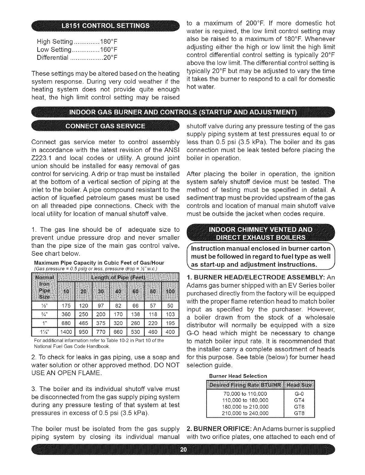
1. The gas line should be of adequate size to
prevent undue pressure drop and never smaller
than the pipe size of the main gas control valve.
See chart below.
Maximum Pipe Capacity in Cubic Feet of Gas/Hour
(Gas pressure =O.5 psig or less, pressure drop = ½" w.c.)
IN
J "
1%"
Foradditionalinformationreferto Table ]0-2 inPart 10 of the
NationalFuel Gas Code Handbook.
2. To check for leaks in gas piping, use a soap and
water solution or other approved method. DO NOT
USE AN OPEN FLAME.
3. The boiler and its individual shutoff valve must
be disconnected from the gas supply piping system
during any pressure testing of that system at test
pressures in excess of 0.5 psi (3.5 kPa).
nstruction manual enclosed in burner carton h
ust be followed in regard to fuel type as well I
s start-up and adjustment instructions, j/
1. BURNER HEAD/ELECTRODE ASSEMBLY: An
Adams gas burner shipped with an EV Series boiler
purchased directly from the factory will be equipped
with the proper flame retention head to match boiler
input as specified by the purchaser. However,
a boiler drawn from the stock of a wholesale
distributor will normally be equipped with a size
G-O head which might be necessary to change
to match boiler input rate. It is recommended that
the installer carry a complete assortment of heads
for this purpose. See table (below) for burner head
selection guide.
Burner Head Selection
70,000 to 110,000
110,000to 180,000
180,000 to 210,000
210,000 to 240,000
G-0
GT4
GT6
GT8
The boiler must be isolated from the gas supply 2. BURNER ORIFICE:AnAdams burner issupplied
piping system by closing its individual manual with two orifice plates, one attached to each end of
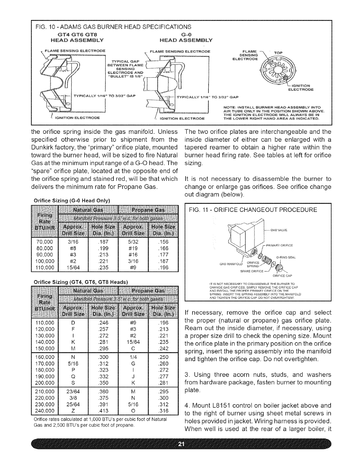
FIG. 10 -ADAMS GAS BURNER HEAD SPECIFICATIONS
GT4 GT6 GT8 G-O
HEAD ASSEMBLY HEAD ASSEMBLY
_GNITNON EL_OT_OOE _GN[_'_ON ELECTAODE TH£ {GNITION ELECTRODE WILL ALV_#AYS BE IFa
T_ LOW_ _G_ ¸ HAND A_EA A8 _ND_CATED_
the orifice spring inside the gas manifold. Unless
specified otherwise prior to shipment from the
Dunkirk factory, the "primary" orifice plate, mounted
toward the burner head, will be sized to fire Natural
Gas at the minimum input range of a G-O head. The
"spare" orifice plate, located at the opposite end of
the orifice spring and stained red, will be that which
delivers the minimum rate for Propane Gas.
Orifice Sizing (G-0 Head Only)
70,000
80,000
90,000
100,000
110,000
3/16
#8
#3
#2
15/64
.187
.199
.213
.221
.235
5/32
#19
#16
3/16
#9
.156
.166
.177
.187
.196
Orifice Sizing (GT4, GT6, GT8 Heads)
The two orifice plates are interchangeable and the
inside diameter of either can be enlarged with a
tapered reamer to obtain a higher rate within the
burner head firing rate. See tables at left for orifice
sizing.
It is not necessary to disassemble the burner to
change or enlarge gas orifices, See orifice change
out diagram (below),
FIG. 11 - ORIFICE CHANGEOUT PROCEDURE
_ _'_/_l_ T_'_ _'TP_R _R_AR_ ¸ ©_1_ ©t_ TH_
110,000
120,000
130,000
140,000
150,000
160,000
170,000
180,000
190,000
200,000
210,000
220,000
230,000
240,000
D .246
F .257
I .272
K .281
M .295
N .300
5/16 .312
P .323
Q .332
S .350
23/64 .360
3/8 .375
25/64 .391
Z .413
#9
#3
#2
15/64
C
1/4
G
I
J
K
M
N
5/16
O
.196
.213
.221
.235
.242
.250
.260
.272
.277
.281
.295
.300
.312
.316
Orifice rates calculated at 1,000 BTU's per cubic foot of Natural
Gas and 2,500 BTU's per cubic foot of propane,
If necessary, remove the orifice cap and select
the proper (natural or propane) gas orifice plate.
Ream out the inside diameter, if necessary, using
a proper size drill to check the opening size. Mount
the orifice plate in the primary position on the orifice
spring, insert the spring assembly into the manifold
and tighten the orifice cap. Do not overtighten.
3. Using three acorn nuts, studs, and washers
from hardware package, fasten burner to mounting
plate.
4. Mount L8151 control on boiler jacket above and
to the right of burner using sheet metal screws in
holes provided in jacket. Wiring harness is provided.
When welt is used at the rear of a larger boiler, it
might be necessaryto relocatethe control with
longerwiringnotprovided.
5. If a tankless coil is included in the boiler, insert the
well for the L8151 remote bulb in the coil plate. Run
capillary tube through sight glass opening in jacket.
6. If the boiler does not include a tankless coil,
install 3A" welt and bulb with a bushing either in the
1½" supply opening opposite the one used to feed
radiation, or in a reducing tee in the 1½" supply
opening that feeds radiation.
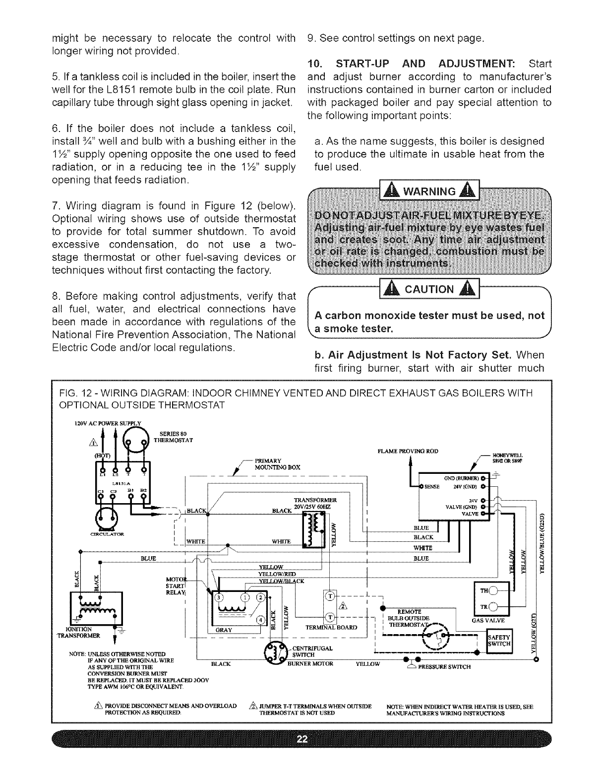
7. Wiring diagram is found in Figure 12 (below).
Optional wiring shows use of outside thermostat
to provide for total summer shutdown. To avoid
excessive condensation, do not use a two-
stage thermostat or other fuel-saving devices or
techniques without first contacting the factory.
8. Before making control adjustments, verify that
all fuel, water, and electrical connections have
been made in accordance with regulations of the
National Fire Prevention Association, The National
Electric Code and/or local regulations.
9. See control settings on next page.
10. START-UP AND ADJUSTMENT: Start
and adjust burner according to manufacturer's
instructions contained in burner carton or included
with packaged boiler and pay special attention to
the following important points:
a. As the name suggests, this boiler is designed
to produce the ultimate in usable heat from the
fuel used.
--[A WAR__.,NGA
carbon monoxide tester must be used, n
smoke tester.
b. Air Adjustment Is Not Factory Set. When
first firing burner, start with air shutter much
FIG. 12 - WIRING DIAGRAM: INDOOR CHIMNEY VENTED AND DIRECT EXHAUST GAS BOILERS WITH
OPTIONAL OUTSIDE THERMOSTAT
120!/AC PO_&rER SUPPLY
10"°"°
THERMOSTAT
FLAME PROVING ROD
13 ! I
LStSIA -- NENSE _V (GND)
[_=.J I t..Im_----- BLACK /BLACK 2DVt25V60HZ | | ] VALVE(GND) g_j._
;w_ , I(LII /l '1 II
LJW,_E _ '_ L_] EII_ _ ' I I I I J
¢= INII
0JI -oh
_[ _A_ --- _YELLOW/BLACK
|-I L '4 "I'ERMIN_'BOARD t I THEEMOSTATS_,_
IF ANY OF THE ORIOINAL WIRE _BURNER MOTOR O_ _1
ASSU_L]m w_rrHTim BLAC_ V_3W _ _RESS_.m_swrrc_
CONVERSION BURNER MUST
BE REPLACED. IT MUST BE REPLA(TED 3OOV
TYPE AWM 1_6°C OR EQUIVALENT,
_z
PROVIDE DISCONNECT MEANS AND OVERLOAD _ JUMPER T-T TERMINALS WHEN OUTSIDE NOTE: WHEN INDIRECT WATER HEATER IS USED. SEE
PROTEL'_.rION AS REQUIRED, THERMOSTAT 1S NOT USED MAN]._ACTURER!S WIRING INSTRUCTIONS
nearer closed than final setting anticipated. At
70 MBH, shutter must be fully closed because
some air always by-passes shutter.
With chamber fully warmed up, find the highest
CO 2 level at which CO of tess than 30 ppm can
be maintained. Final setting should be at least
9% CO. If unable to obtain that reading, check
for air leaks, incorrect flame retention head or
for the eductor tube not centered. For chimney
vented boilers, draft wilt vary as air is adjusted.
It should be left at as near zero as possible at
breeching.
c. The correct input rate is the smallest which
will do the job properly. Long continuous runs
with minimum starts and stops conserve the
most energy.
rate that is too low can cause I
k..corrosive condensation in boiler and flue. j)
d. All orifice sizes are approximate. Actual burner
input wilt vary with heating values of gas sup-
plied locally.
e. The input for natural gas can be determined
by timing the gas meter. To vary the gas input,
install the nearest size orifice, and adjust the
pressure regulator up or down for the exact
input desired. Measure the manifold pressure at
the pressure tap on gas valve.
eOTE: Do not exceed pressure adjustment rang h
commended by the gas valve manufacturer, not less I
Ik,t,han 3" and not greater than 4" of H20. J
11. IF PUBLIC UTILITY REGULATIONS IN
YOUR COMMUNITY REQUIRE LABELING OF
THE BOILER WITH BURNER HEAD SIZE AND
FIRING RATE, PLEASE USE LABEL IN BOILER
LITERATURE ENVELOPE FOR THAT PURPOSE.
('Complete installation must be made inh
accordance with the requirements of local I
authorities and the National Fire Protection I
With all high efficiency boilers, care must be taken
to minimize condensation. Therefore, cold standby
is not recommended and may be used only with a
piping bypass as shown in Figure 6. This requires
a change in control wiring. Please contact factory
prior to making that change.
When cold standby is not utilized, the homeowner
might possibly object to the burner starting when
space heat is not required. To avoid this, an optional
outside thermostat may be used to shut down the
system totally when outside temperature is above a
specific limit set by the homeowner. When outside
thermostat is not used, jumper T-T Terminals.
High Setting - Not less than 200°F, 20°F or more
above Low Setting.
Low Setting - Not less than 180°F for best
tanktess coil output. Lower settings may be used
when tankless coil is not a factor.
Differential - 20°F typical. May be changed to
match system.
1. Place boiler at a location as centralized as
possible with the piping system and as free from
unusual wind currents as possible,
2. A level concrete or noncombustible base is
recommended with the top high enough so that
ground water and melted snow will not rise as high
as the bottom of the boiler. It is also recommended
that crushed stone or gravel surround the base to
keep shrubbery, weeds and grass at least 18" from
the boiler.
3. If necessary, level boiler with shims placed
beneath feet.
4. Accessibility clearances must take precedence
over fire protection clearances. Allow at least 24"
for servicing at the front and burner sides of the
boiler. Allow at least 18" at a side where passage is
required to another side for servicing. A 6" clearance
from combustible material on all sides and the top
is recommended.
5. Advise owner to maintain air passages free from
obstructions. Ventilating and combustion air must
enter boiler casing without restrictions.
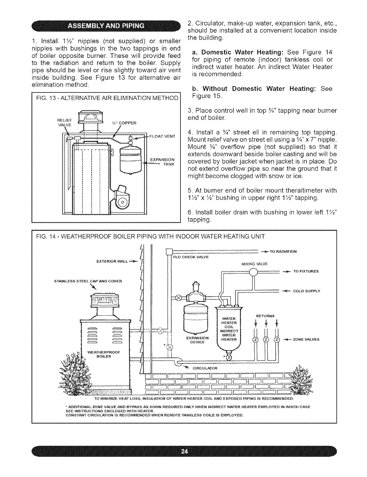
1. Install 1½" nipples (not supplied) or smaller
nippleswith bushingsin the two tappingsin end
of boileroppositeburner.Thesewill providefeed
to the radiation and return to the boiler. Supply
pipeshouldbe levelor rise slightlytowardair vent
inside building. See Figure 13 for alternativeair
eliminationmethod.
FIG. 13 - ALTERNATIVE AI R ELIMINATION METHOD
,FLOAT VENT
E XPAr'_$_ON
SANK
2. Circulator, make-up water, expansion tank, etc.,
should be installed at a convenient location inside
the building.
a. Domestic Water Heating: See Figure 14
for piping of remote (indoor) tanktess coil or
indirect water heater. An indirect Water Heater
is recommended.
b. Without Domestic Water Heating: See
Figure 15.
3. Place control welt in top ¾" tapping near burner
end of boiler.
4. Install a ¾" street ell in remaining top tapping.
Mount relief vatve on street ell using a ¾" x 7" nipple.
Mount ¾" overflow pipe (not supplied) so that it
extends downward beside boiler casting and will be
covered by boiler jacket when jacket is in place. Do
not extend overflow pipe so near the ground that it
might become clogged with snow or ice.
5. At burner end of boiler mount theraltimeter with
1½" x ½" bushing in upper right 1½" tapping.
6. Install boiler drain with bushing in lower left 1½"
tapping.
FIG. 14 - WEATHERPROOF BOILER PIPING WITH INDOOR WATER HEATING UNIT
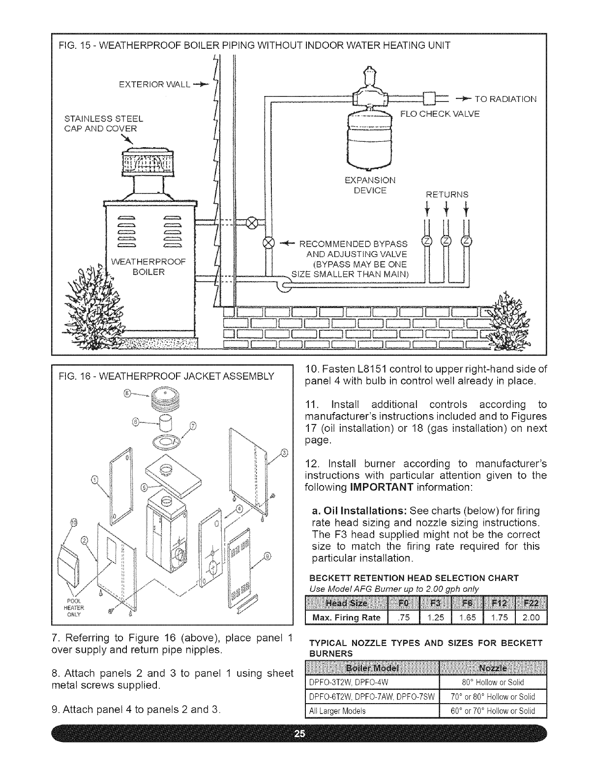
FIG. 15 - WEATHERPROOF BOILER PIPING WITHOUT INDOOR WATER HEATING UNIT
STAINLESSSTEE l,I VA,VE
LI ! !
/11
1 I 't EXPANSION
l DEVICE RETURNS
_L_ _, RECOMMENDED BYPASS _]9(_ _ _1 _
/I AND ADJUSTING VALVE H H I_
_: b WEATHERPROOF /_ (BYPASS MAY BE ONE H H H
FIG. 16 - WEATHERPROOF JACKETASSEMBLY
ONL_
7. Referring to Figure 16 (above), place panel 1
over supply and return pipe nipples.
8. Attach panels 2 and 3 to panel 1 using sheet
metal screws supplied.
10. Fasten L8151 control to upper right-hand side of
panel 4 with bulb in control welt already in place.
11. Install additional controls according to
manufacturer's instructions included and to Figures
17 (oil installation)or 18 (gas installation)on next
page.
12. Install burner according to manufacturer's
instructions with particular attention given to the
following IMPORTANT information:
a. Oil Installations: See charts (below) for firing
rate head sizing and nozzle sizing instructions,
The F3 head supplied might not be the correct
size to match the firing rate required for this
particular installation,
BECKETT RETENTION HEAD SELECTION CHART
Use Model AFG Burner up to 2.00 gph only
Max. Firing Rate .75 1.25 1.65 1.75 2.00
TYPICAL NOZZLE TYPES AND SIZES FOR BECKETT
BURNERS
DPFO-3T2W,DPFO-4W
DPFO-6T2W, DPFO-7AW, DPFO-7SW
@iii
80° Hollowor Solid
70° or80° Hollowor Solid
60° or70° Hollowor Solid
9. Attach panel 4 to panels 2 and 3. All Larger Models
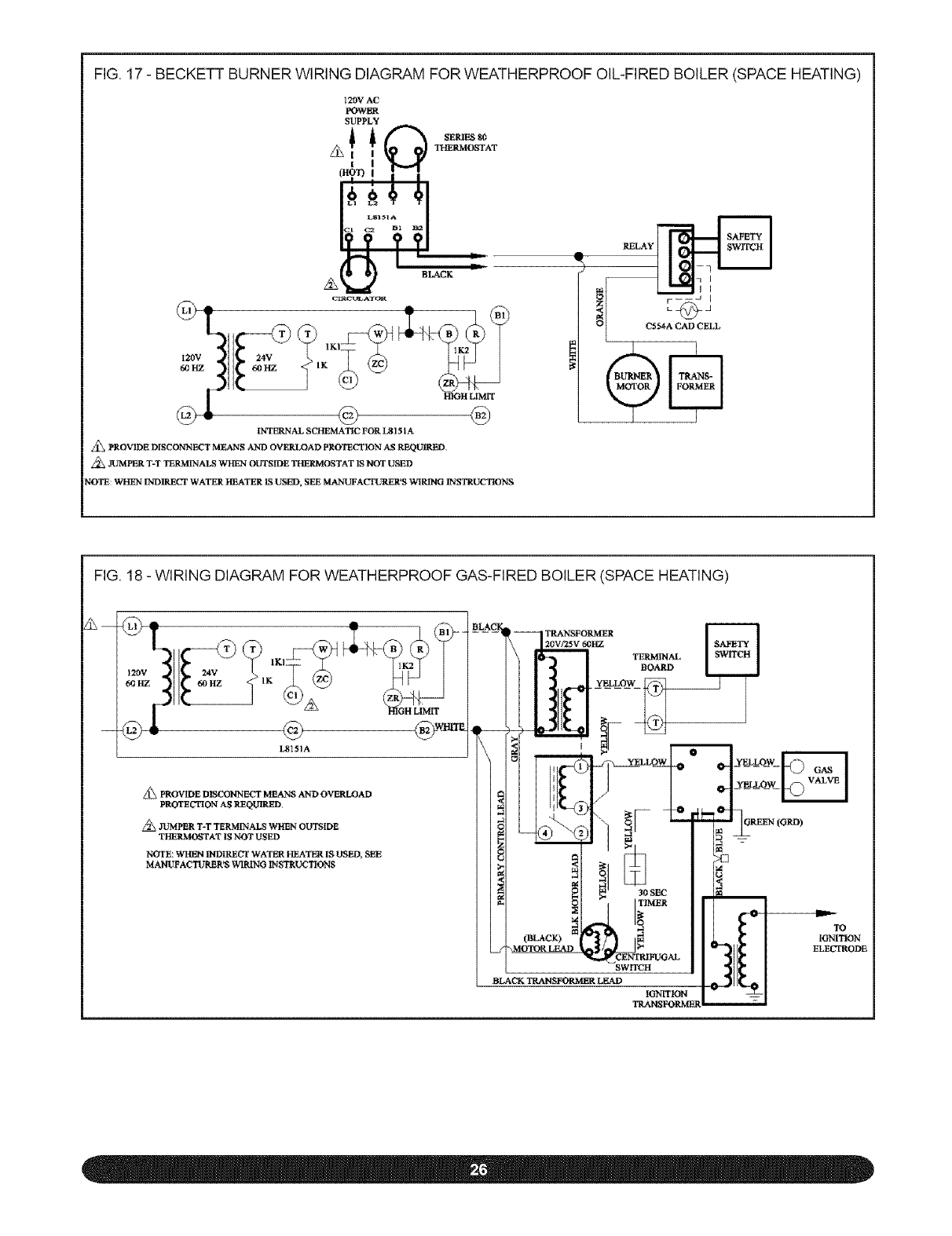
FIG, 17 - BECKETT BURNER WIRING DIAGRAM FOR WEATHERPROOF OIL-FIRED BOILER (SPACE HEATING)
12OV AC
POWER
SUPPLY
!i_ I SEPd_ 8O
THERMOSTAT
It#
I?? ??1
Cll_C_LATOR
/ "¢'T A
@, @
FNTEP_NAL SCHEMATIC FOR LgI51A
Z_ PROVIDE DISCONNECT MEANS AND OVERLOAD PROTIgCTIDN AS REQUIt_BD
,lUMPER T-T TERMINALS WHEN OUTSIDE TtI£RMOSTAT IS NOT U,!_D
NOTE: WHEN INDIRECT WATER HEATER IS USED, SEE MANUFACTURER'S WIRING INSTRUCTIONS
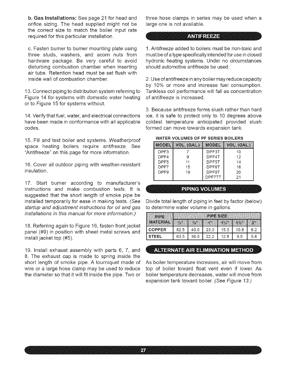
FIG. 18 - WIRING DIAGRAM FOR WEATHERPROOF GAS-FIRED BOILER (SPACE HEATING)
120V 24V 11Kl 1K2
APROVIDE DISCONNECT MEANS AND OVEgLOAD
PROTECTION AS REQUIRED
JUMPER T-T TERM[tqALS WHEN OUTSIDE
THERMOSTAT IS NOT USED
NOTE WHEN INDIRECT WATER HEATER IS USED_ SEE
MA]ffUFACTUP-.ER'$ WIRING INSTRUCTIONS
R_ER TERMfNAL
BOARD
30 SEC
li=,
SWITCH
BLACK TRANSFORMER LEAD
IGNITION
_9
IGNITION
ELECTRODE
b. Gas Installations: See page 21 for head and
orifice sizing. The head supplied might not be
the correct size to match the boiler input rate
required for this particular installation.
c. Fasten burner to burner mounting plate using
three studs, washers, and acorn nuts from
hardware package. Be very careful to avoid
disturbing combustion chamber when inserting
air tube. Retention head must be set flush with
inside watt of combustion chamber.
13. Connect piping to distribution system referring to
Figure 14 for systems with domestic water heating
or to Figure 15 for systems without.
14. Verify that fuet, water, and electrical connections
have been made in conformance with all applicable
codes.
15. Fill and test boiler and systems. Weatherproof
space heating boilers require antifreeze. See
"Antifreeze" on this page for more information.
16. Cover all outdoor piping with weather-resistant
insulation.
17. Start burner according to manufacturer's
instructions and make combustion tests. It is
suggested that the short length of smoke pipe be
installed temporarily for ease in making tests. (See
startup and adjustment instructions for oil and gas
installations in this manual for more information.)
18. Referring again to Figure 16, fasten front jacket
panel (#9) in position with sheet metal screws and
install jacket top (#5).
19. Install exhaust assembly with parts 6, 7, and
8. The exhaust cap is made to spring inside the
short length of smoke pipe. A tourniquet made of
wire or a large hose clamp may be used to reduce
the diameter so that it will fit inside the pipe. Two or
three hose clamps in series may be used when a
large one is not available.
1. Antifreeze added to boilers must be non-toxic and
must be of a type specifically intended for use in closed
hydronic heating systems. Under no circumstances
should automotive antifreeze be used.
2. Use of antifreeze in any boiler may reduce capacity
by 10% or more and increase fuel consumption.
Tanktess coil performance wilt fall as concentration
of antifreeze is increased.
3. Because antifreeze forms slush rather than hard
ice, it is safe to protect only to 10 degrees above
coldest temperature anticipated provided slush
formed can move towards expansion tank.
WATERVOLUMES OF PF SERIES BOILERS
N
DPF3 7
DPF4 9
DPF5 11
DPF7 15
DPF9 19
DPF3T
DPF4T
DPF5T
DPF6T
DPFST
DPF7TT
10
12
14
16
2o
21
Divide total length of piping in feet by factor (below)
to determine water volume in gallons.
COPPER
STEEL
As boiler temperature increases, air wilt move from
top of boiler toward float vent even if lower. As
boiler temperature decreases, water will move from
expansion tank toward boiler. (See Figure 13.)
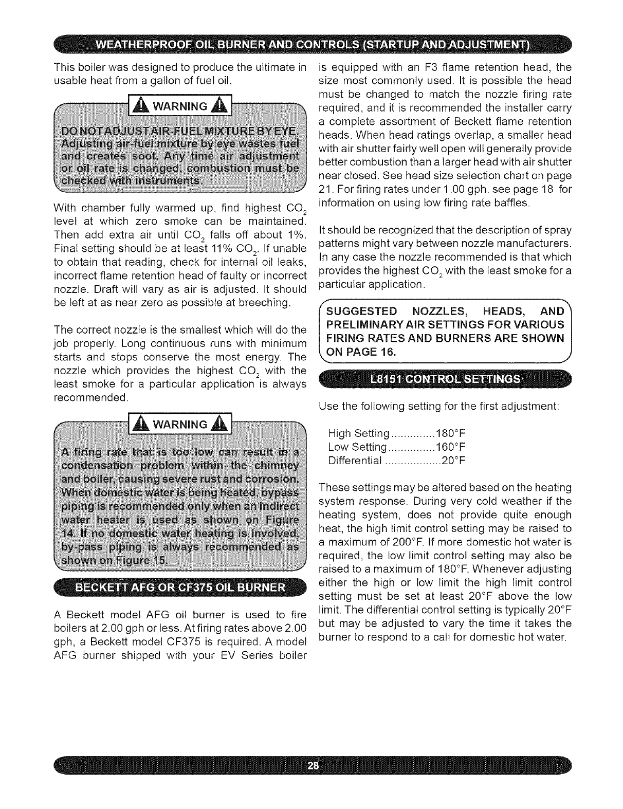
This boiler was designed to produce the ultimate in
usable heat from a gallon of fuel oil.
With chamber fully warmed up, find highest CO 2
level at which zero smoke can be maintained.
Then add extra air until CO 2 falls off about 1%.
Final setting should be at least 11% CO 2. If unable
to obtain that reading, check for internal oil leaks,
incorrect flame retention head of faulty or incorrect
nozzle. Draft wilt vary as air is adjusted. It should
be left at as near zero as possible at breeching.
The correct nozzle is the smallest which will do the
job properly. Long continuous runs with minimum
starts and stops conserve the most energy. The
nozzle which provides the highest CO 2 with the
least smoke for a particular application is always
recommended.
A Beckett model AFG oil burner is used to fire
boilers at 2.00 gph or less. At firing rates above 2.00
gph, a Beckett model CF375 is required. A model
AFG burner shipped with your EV Series boiler
is equipped with an F3 flame retention head, the
size most commonly used. It is possible the head
must be changed to match the nozzle firing rate
required, and it is recommended the installer carry
a complete assortment of Beckett flame retention
heads. When head ratings overlap, a smaller head
with air shutter fairly well open will generally provide
better combustion than a larger head with air shutter
near closed. See head size selection chart on page
21. For firing rates under 1.00 gph. see page 18 for
information on using low firing rate baffles.
It should be recognized that the description of spray
patterns might vary between nozzle manufacturers.
In any case the nozzle recommended is that which
provides the highest CO 2with the least smoke for a
particular application.
RELIMINARY AIR SETTINGS FOR VARIOUS I
IRING RATES AND BURNERS ARE SHOWN I
N PAGE 16. 1"")
Use the following setting for the first adjustment:
High Setting .............. 180°F
Low Setting ............... 160°F
Differential .................. 20°F
These settings may be altered based on the heating
system response. During very cold weather if the
heating system, does not provide quite enough
heat, the high limit control setting may be raised to
a maximum of 200°F. If more domestic hot water is
required, the low limit control setting may also be
raised to a maximum of 180°F. Whenever adjusting
either the high or low limit the high limit control
setting must be set at least 20°F above the low
limit. The differential control setting is typically 20°F
but may be adjusted to vary the time it takes the
burner to respond to a call for domestic hot water.
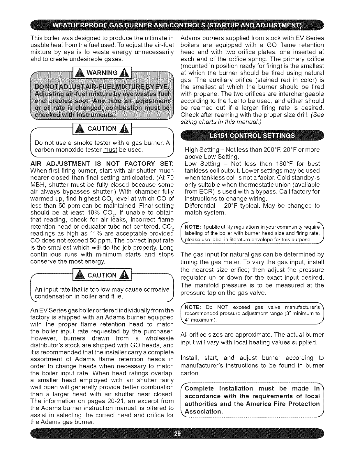
Thisboilerwasdesignedto producetheultimatein
usableheatfromthefuelused.Toadjusttheair-fuel
mixtureby eye is to waste energy unnecessarily
ahdto createundesirablegases.
!c
o not use a smoke tester with a gas burner. A I
arbon monoxide tester must be used. J
AIR ADJUSTMENT IS NOT FACTORY SET:
When first firing burner, start with air shutter much
nearer closed than final setting anticipated. (At 70
MBH, shutter must be fully closed because some
air always bypasses shutter.) With chamber fully
warmed up, find highest CO 2 level at which CO of
less than 50 ppm can be maintained. Final setting
should be at least 10% CO 2. If unable to obtain
that reading, check for air leaks, incorrect flame
retention head or educator tube not centered. CO 2
readings as high as 11% are acceptable provided
CO does not exceed 50 ppm. The correct input rate
is the smallest which wilt do the job properly. Long
continuous runs with minimum starts and stops
conserve the most energy.
n input rate that is too low may cause corrosive I
ndensa!ion in boi!er and !!ue: J
An EV Series gas boiler ordered individually from the
factory is shipped with an Adams burner equipped
with the proper flame retention head to match
the boiler input rate requested by the purchaser.
However, burners drawn from a wholesale
distributor's stock are shipped with GO heads, and
it is recommended that the installer carry a complete
assortment of Adams flame retention heads in
order to change heads when necessary to match
the boiler input rate. When head ratings overlap,
a smaller head employed with air shutter fairly
well open will generally provide better combustion
than a larger head with air shutter near closed.
The information on pages 20-21, an excerpt from
the Adams burner instruction manual, is offered to
assist in selecting the correct head and orifice for
the Adams gas burner.
Adams burners supplied from stock with EV Series
boilers are equipped with a GO flame retention
head and with two orifice plates, one inserted at
each end of the orifice spring. The primary orifice
(mounted in position ready for firing) is the smallest
at which the burner should be fired using natural
gas. The auxiliary orifice (stained red in color) is
the smallest at which the burner should be fired
with propane. The two orifices are interchangeable
according to the fuel to be used, and either should
be reamed out if a larger firing rate is desired.
Check after reaming with the proper size drill. (See
sizing charts in this manual.)
High Setting - Not less than 200°F, 20°F or more
above Low Setting.
Low Setting - Not less than 180°F for best
tankless coil output. Lower settings may be used
when tanktess coil is not a factor. Cold standby is
only suitable when thermostatic union (available
from ECR) is used with a bypass. Call factory for
instructions to change wiring.
Differential - 20°F typical. May be changed to
match system.
OTE: If public utility regulations in your community require"_
beling of the boiler with burner head size and firing rate, I
ease use label in literature envelope for this purpose. .._
The gas input for natural gas can be determined by
timing the gas meter. To vary the gas input, install
the nearest size orifice; then adjust the pressure
regulator up or down for the exact input desired.
The manifold pressure is to be measured at the
pressure tap on the gas valve.
OTE: Do NOT exceed gas valve manufacturer's"_
commended pressure adjustment range (3" minimum to !
All orifice sizes are approximate. The actual burner
input will vary with local heating values supplied.
Install, start, and adjust burner according to
manufacturer's instructions to be found in burner
carton.
omplete installation must be made in"_
ccordance with the requirements of local I
uthorities and the America Fire Protection I
ssociation, j)
On a call for heat, the thermostat will actuate, com-
pleting the circuit to the aquastat. In turnm the circu-
lator and ignition systems are activated and ignition
will begin. In the event the boiler water temperature
exceeds the high limit setting on the boiler mount-
ed aquastat, power will be interrupted between the
aquastat and the ignition system. The power will
remain off until the boiler water temperature drops
below the high limit setting. The circulator wilt con-
tinue to operate under this condition until the ther-
mostat is satisfied.
ing the circuit to the ignition system. For oil burners
the switch wilt reset after the burner goes out post-
purge and attempt to relight. After three attempts to
light, the burner wilt go into permanent lockout.
Do not attempt to place the boiler back into op--'_
ration. Contact a qualified service agency. .i/
Should a blocked flue condition occur, the blocked
vent safety switch wilt shut the fuel to the main
burner off.
Should a blocked flue condition occur, the pres- (Do not attempt to place the boiler back into oph
sure switch will sense a drop in pressure, open- _ration. Contact a qualified service agency. .J
LT!i!!
Before operating, make certain the boiler and
system are full of water to minimum pressure
(this is usually 12 Ibs. per square inch on most
systems) and system is vented of air. See the
k operating and lighting instructions, j
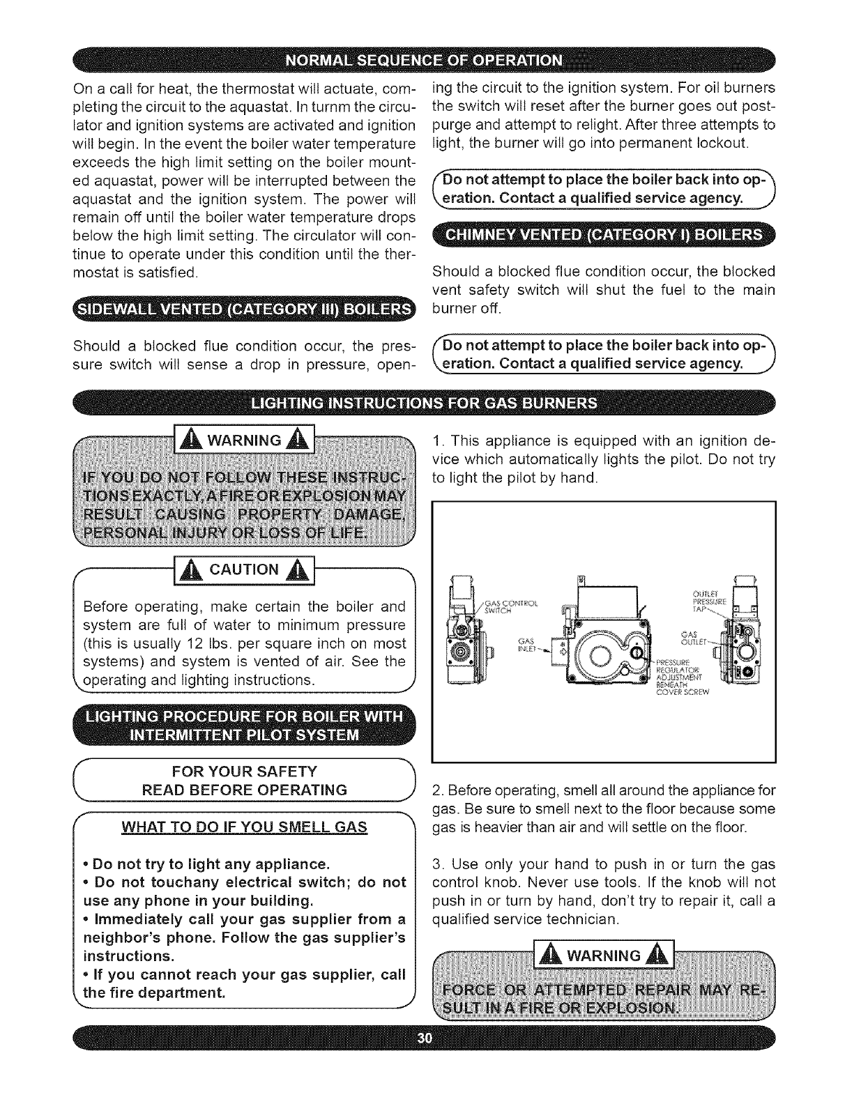
1. This appliance is equipped with an ignition de-
vice which automatically lights the pilot. Do not try
to light the pilot by hand.
!AP.,
AZ))b_ _4 _4
_R_RE FOR YOUR SAFETY
ApB FOREOPERA ING
WHAT TO DO IF YOU SNELL GAS
• Do not try to light any appliance.
, Do not touchany electrical switch; do not
use any phone in your building.
, Immediately call your gas supplier from a
neighbor's phone. Follow the gas supplier's
instructions.
If you cannot reach your gas supplier, call
_the fire department. J
2. Before operating, smell all around the appliance for
gas. Be sure to smell next to the floor because some
gas is heavier than air and will settle on the floor.
3. Use only your hand to push in or turn the gas
control knob. Never use tools. If the knob wilt not
push in or turn by hand, don't try to repair it, call a
qualified service technician.
4. Do not use this appliance if any part has been
under water. Immediately call a qualified service
technician to inspect the appliance and to replace
any part of the control system and gas control which
has been under water.
1. STOP! Read the safety information in the user's
information manual.
2. Set thermostat to lowest setting.
3. Turn off all electric power to the appliance.
4. This appliance is equipped with an ignition de-
vice which automatically lights the pilot. DO NOT
TRY TO LIGHT THE PILOT BY HAND.
Remove the vent pipe at the base of the chimney or
flue and, using a mirror, check for obstruction.
The lever of the pressure relief valve on the boiler
should be operated periodically to make sure that
it is functioning properly. The pressure relief valve
should open before the water pressure exceeds
the 30 lb. reading on the gauge. If this pressure is
exceeded and the pressure relief valve leaks water
when the boiler is operating at normal pressures,
it should be immediately replaced. Corrosion can
build up rapidly at the valve seat and prevent its
functioning as a safety device.
,,_ WARNING ,,_
5. Turn gas control knob clockwise to "OFF."
6. Wait five (5) minutes to clear out any gas. If you
then smell gas, STOP, and follow in the safety infor-
mation "What To Do If You Smell Gas." If you don't
smell gas, go to the next step.
7. Turn gas control knob counterclockwise to
"ON ."
8. Turn on all electric power to the appliance.
9. Set thermostat to desired setting.
10.If the appliance will not operate, follow the in-
structions "To Turn Off Gas To Appliance" (below)
and call a qualified service technician or your gas
supplier.
(See off burner instructions for nozzle and electrode setting.)
1. Check oil burner nozzle to make certain it is tight
in adapter. Burner mounting bolts should be tight.
2. Check electrode setting, as they may have been
jarred out of position during transportation.
3. Lubricate burner motor and circulator motor if re-
quired. Some circulators are water lubricated and
do not require oiling.
4. Set room thermostat to call for heat, or jump
thermostat contacts on the boiler control.
5. Open all oil line valves.
1. Set thermostat to lowest setting.
2. Turn off all electric power to the appliance if ser-
vice is to be performed.
3. Turn gas control knob clockwise to "OFF." DO
NOT FORCE.
6. Turn service switch on. Burner should start.
7. On one pipe fuel systems only, vent pump as
soon as burner starts. Allow oil to run until all traces
of air in the suction line disappear.
8. Turn "OFF" burner and install pressure gauge
port on pump.
The venting system should be inspected at the start
of each heating season. Check the vent pipe from
the boiler to the chimney for signs of deterioration
by rust or sagging joints. Repair if necessary.
9. Start burner again and check oil pressure for 140
pounds. Adjust if necessary.
DO NOT SET FIRE VISUALLY L _J
Instruments are the only reliable method to deter-
mine proper air adjustments. An improperly adjust-
ed burner causes soot and high fuel bills because
of incomplete combustion of the fuel oil. This in turn
may require excessive boiler maintenance, service
costs, and in some instances, house cleaning or re-
decorating. A competent service mechanic should
be consulted to make the proper adjustments with a
smoke tester, CO 2indicator and draft gauge. Bacha-
rach or Dwyer test kits include these instruments.
locks out, ignition stops, motor stops and oil
valve - when used - closes. To restart, open
oil supply valve and reset safety switch.
•Ignition Failure: With burner off, close oil
supply valve and run through start-up proce-
dure, The safety switch should lock out as in
flame failure.
*Power Failure: Turn off main power supply
switch while burner is operating. When burn-
er stops, restore power and burner should
start.
A ¼" diameter slot is provided in the inspection
cover plate to take draft readings in the combustion
chamber. A ¼" diameter hole wilt be required in the
flue pipe between the boiler and barometric damper
(if used) to take draft, CO2, smoke and temperature
readings. Adjust air shutter on oil burner to obtain
a "trace" of smoke. Measure CO 2 at this point. In-
crease air adjustment to lower CO 2approximately
1%. Check to insure minimum -.02 w.c. "overfire"
draft, and zero smoke. If -.02 w.c. "overfire" draft can
not be maintained, changes and/or modifications
may be required in the venting or the chimney.
CHECK SAFETY CONTROL CIRCUIT after burner
adjustments have been made for satisfactory per-
formance.
1. High Limit Control: Remove cover and note
temperature setting. With the burner operat-
ing, decrease this setting to the minimum point.
When boiler water temperature exceeds this set
point, the high limit switch will open, shutting off
the power to the oil burner. Return setting to de-
sired high limit point. Burner should restart.
2. Primary Control and Flame Sensor:
To Check:
*Flame Failure: Simulate by shutting off oil
supply with hand valve while burner is on. Six-
ty seconds after flameout, the safety switch
If operation is not as described as above, check
wiring and controls.
PREVENTIVE MAINTENANCE of an oil fired boiler
reduces operating costs. The boiler and vent pipe
should be inspected for accumulation of soot or
scale deposits periodically but at least once every
year before the start of each heating season. When
soot is present on the section walls and flueways,
improper combustion will result, causing additional
sooting and scaling until flueways are completely
closed. To remove soot and scale from the flue-
ways, remove top jacket panel, top clean-out plate,
open burner swing door.
PERIODIC INSPECTION and tightening of the tan-
kless heater/cover plate bolts wilt reduce the risk
of leaks,
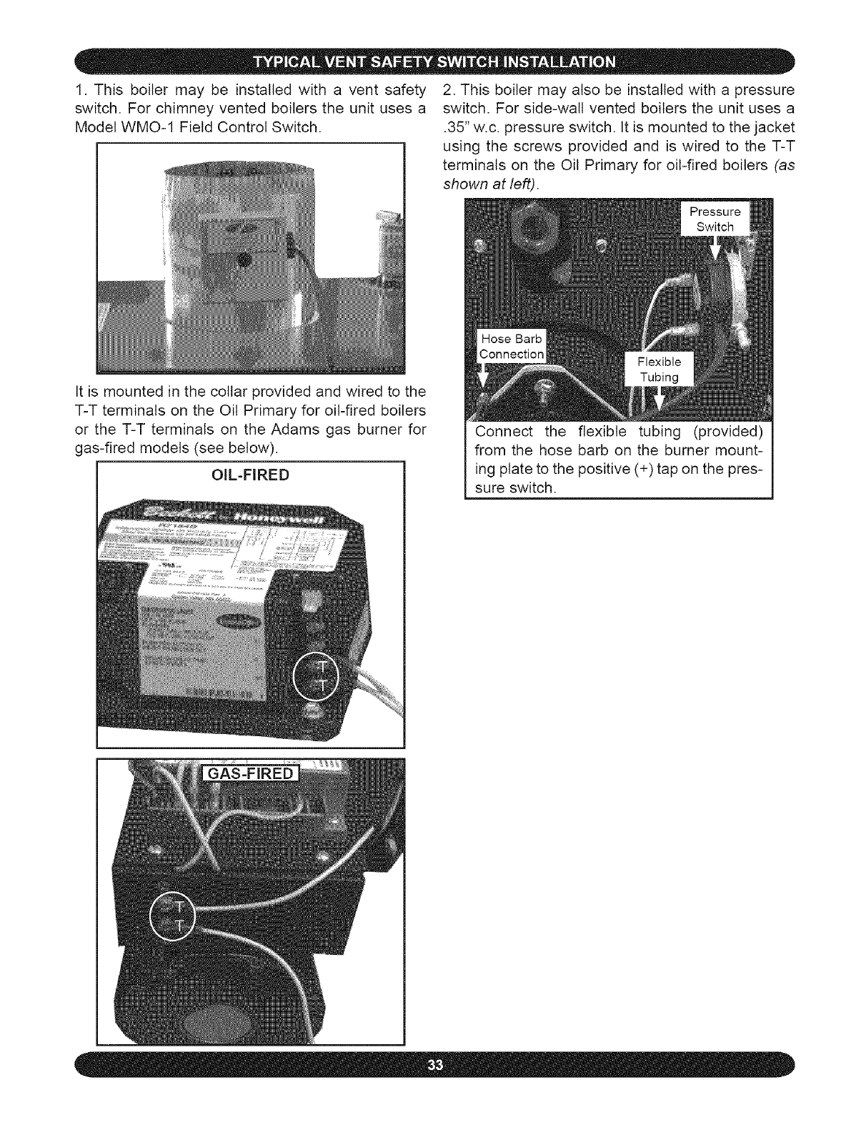
1. This boilermay be installedwith a vent safety
switch.For chimneyventedboilersthe unituses a
ModelWMO-1FieldControlSwitch.
2. Thisboilermayalsobe installedwitha pressure
switch.Forside-wallventedboilerstheunitusesa
.35"w.c.pressureswitch.Itis mountedto thejacket
usingthe screwsprovidedand is wiredto the T-T
terminalson the Oil Primaryfor oil-firedboilers(as
shown at left).
It is mounted in the collar provided and wired to the
T-T terminals on the Oil Primary for oil-fired boilers
or the T-T terminals on the Adams gas burner for
gas-fired models (see below).
OIL-FIRED
Connect the flexible tubing (provided)
from the hose barb on the burner mount-
ing plate to the positive (+) tap on the pres-
sure switch.
GAS-FIRED
To assuretrouble-freeoperation,we recommend
thatyouhavethefluepassages,burner,combustion
chamber,burneradjustmentand operationof the
controls checked once a year by a competent
servicetechnician,
Beforethe start of each season(or whenever the
systemhasbeenshutdownforsometime)re-check
the whole system for leaks, includingthe boiler
and vent pipe, Replaceor patch any faulty boiler
seals,Checkthe siliconerubberseals aroundthe
fluecollector,betweenboilersections,and around
the fire door,Ensurethat there are no leaks, Use
RTVsiliconerubberadhesivesealant(availablein
caulkinggun tubes) ratedfor 400°F to replaceor
repairsealsin locationswhereoriginalseals have
deteriorated,
Flue passagesbetweenboilersectionsshouldbe
examinedannuallyand cleanedif necessary,See
cleaninginstructionsthatfollow,
abel all wires prior to disconnectionwhen I
ervicing controls, Wiring errors can cause I
properanddangerousoperation,Verifyproper I
Perationafter se_icing: J
Drain it until pressure is reduced below the safe
limit, Then have the valve replaced immediately,
The relief valve should be tested monthly, Refer to
valve manufacturer's instructions packaged with
relief valve,
The expansion tank may become waterlogged or
may receive an excess of air. Frequent automatic
opening of the relief valve indicates water logging. A
high boiler temperature accompanied by unusually
low radiation unit temperature (and "knocking")
indicates excess air in tank.
To correct either condition, close the valve between
the boiler and the tank, Drain the tank until it is
empty, Check all the tank plugs and fittings, Tighten
as necessary, Open the valve between the boiler
and tank, Water will rise to the normal height in the
tank if you have an automatic fill valve (otherwise,
manually refill the system),
If system is to remain out of service during freezing
weather and does not contain antifreeze, always
drain it completely. Water left in to freeze will
crack the pipes and/or boiler.
Visually inspect the entire venting system once
a month for any signs of leakage or deterioration.
If the vent shows any signs of leaking, replace it
immediately,
Do not connect directly to a drain, but leave an air
gap. No shut-off of any description shall be placed
between the safety relief valve and the boiler, or
on discharge pipes between such safety valves
and the atmosphere. Installation of the safety relief
valve shall conform to the ANSI/ASME Boiler and
pressure Vessel Code, Section IV. The manufacturer
is not responsible for any water damage.
Where used, antifreeze solution must be checked
at least once a year in the manner recommended by
the manufacturer of the antifreeze. The antifreeze
includes a corrosion inhibitor that can become
depleted in time, causing the solution to become
corrosive. It is important that this be checked and
the inhibitor be replenished or the system be refilled
with fresh antifreeze solution, whichever may be
required.
Antifreeze must be non-toxic, and of a type
specifically intended for use in closed hydronic
heating systems, Under no circumstances should
automotive antifreeze be used,
This valve should open automatically when the
system pressure exceeds the safe limits (30
pounds per square inch). Should it ever fail to
open under this condition, shut down your system.
The tanktess coil gasket should be checked at
least twice a year, for leakage, and replaced if
necessary.
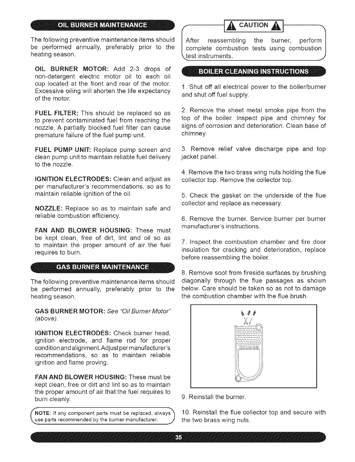
Thefollowingpreventivemaintenanceitemsshould
be performed annually, preferably prior to the
heatingseason.
OIL BURNER MOTOR: Add 2-3 drops of
non-detergent electric motor oil to each oil
cup located at the front and rear of the motor.
Excessive oiling wilt shorten the life expectancy
of the motor.
FUEL FILTER: This should be replaced so as
to prevent contaminated fuel from reaching the
nozzle. A partially blocked fuel filter can cause
premature failure of the fuel pump unit.
Ic [A .
fter reassembling the burner, perform I
omplete combustion tests using combustion I
est instruments. ,,,,,2
1. Shut off all electrical power to the boiler/burner
and shut off fuel supply.
2. Remove the sheet metal smoke pipe from the
top of the boiler. Inspect pipe and chimney for
signs of corrosion and deterioration. Clean base of
chimney.
FUEL PUMP UNIT: Replace pump screen and
clean pump unit to maintain reliable fuel delivery
to the nozzle.
IGNITION ELECTRODES: Clean and adjust as
per manufacturer's recommendations, so as to
maintain reliable ignition of the oil.
NOZZLE: Replace so as to maintain safe and
reliable combustion efficiency.
FAN AND BLOWER HOUSING: These must
be kept clean, free of dirt, lint and oil so as
to maintain the proper amount of air the fuel
requires to burn.
3. Remove relief valve discharge pipe and top
jacket panel.
4. Remove the two brass wing nuts holding the flue
collector top. Remove the collector top.
5. Check the gasket on the underside of the flue
collector and replace as necessary.
6. Remove the burner. Service burner per burner
manufacturer's instructions.
7. Inspect the combustion chamber and fire door
insulation for cracking and deterioration, replace
before reassembling the boiler,
The following preventive maintenance items should
be performed annually, preferably prior to the
heating season.
8. Remove soot from fireside surfaces by brushing
diagonally through the flue passages as shown
below. Care should be taken so as not to damage
the combustion chamber with the flue brush.
GAS BURNER MOTOR: See "Oil Burner Motor"
(above).
IGNITION ELECTRODES: Check burner head,
ignition electrode, and flame rod for proper
condition and alignment.Adjust per manufacturer's
recommendations, so as to maintain reliable
ignition and flame proving.
FAN AND BLOWER HOUSING: These must be
kept clean, free or dirt and lint so as to maintain
the proper amount of air that the fuel requires to
burn cleanly.
OTE: If any component parts must be replaced, always_
se parts recommended by the burner manufacturer. J
9. Reinstall the burner.
10. Reinstall the flue collector top and secure with
the two brass wing nuts.
11. Reinstallthe top jacket panel. Reconnectthe
fluepipe.Reinstallreliefvalvedischargepipe.
12. Reconnect the electrical and fuel supplies.
13. Fire the burner, checking for proper combustion
using combustion test equipment and making
adjustments as necessary.
14. Insure that all safety controls and operating
controls are functioning properly.
Keep your boiler and the area around it clean.
Never burn garbage, paper, or any material other
than the specified fuel in your boiler and never
leave combustible material near or around it.
Have your boiler checked each year by a qualified
service technician.
iWJ]ii_i
',IA _H
YOU MAY AVOID INCONVENIENCE AND SERVICE CALLS BY CHECKING THESE POINTS BEFORE YOU CALL FOR
SERVICE. HAVE YOUR SERVICE TECHNICIAN CHECK ANY PROBLEM YOU ARE UNABLE TO CORRECT.
Thermostat is not set correctly.
Boiler and/or burner may be dirty.
Burner may not be firing at proper rate.
SYSTEM NOT
HEATING
OR GIVING
ENOUGH HEAT
Burner may be short-cycling.
No power to boiler.
Controls out of adjustment.
Radiators not heating.
Circulating pump not running.
Poor electrical contact.
i}i: :ii i iiii i
N@ @@ @@
Air in system.
RADIATORS
NOISY
Reset thermostat above room temperature.
Clean all flue passages and the vent pipe. Have burner cleaned
i and readjusted.
i Check nozzle size or orifice size if there is any doubt. Have
burner adjusted.
i Short-cycling (too frequent off and on) of burner will cause
i sooting. If boiler and/or burner become dirty at frequent intervals,
after correcting the "dirt condition" also correct the control setting
i(or other cause of the short-cycling). Check thermostat heat
anticipator and correct setting, if necessary per instruction sheet
I packed with thermostat.
i Check over-current protection. Check to be sure power supply
circuit is "ON."
Reset according to instructions packed with controls.
Open radiator vents to vent excess air. Check flow control valve
(if used). It may be in closed position.
iCheck relay operation.
Check all control terminals and wire joints.
@8 N i i i:1
Open radiator vents to vent air. Check expansion tank.
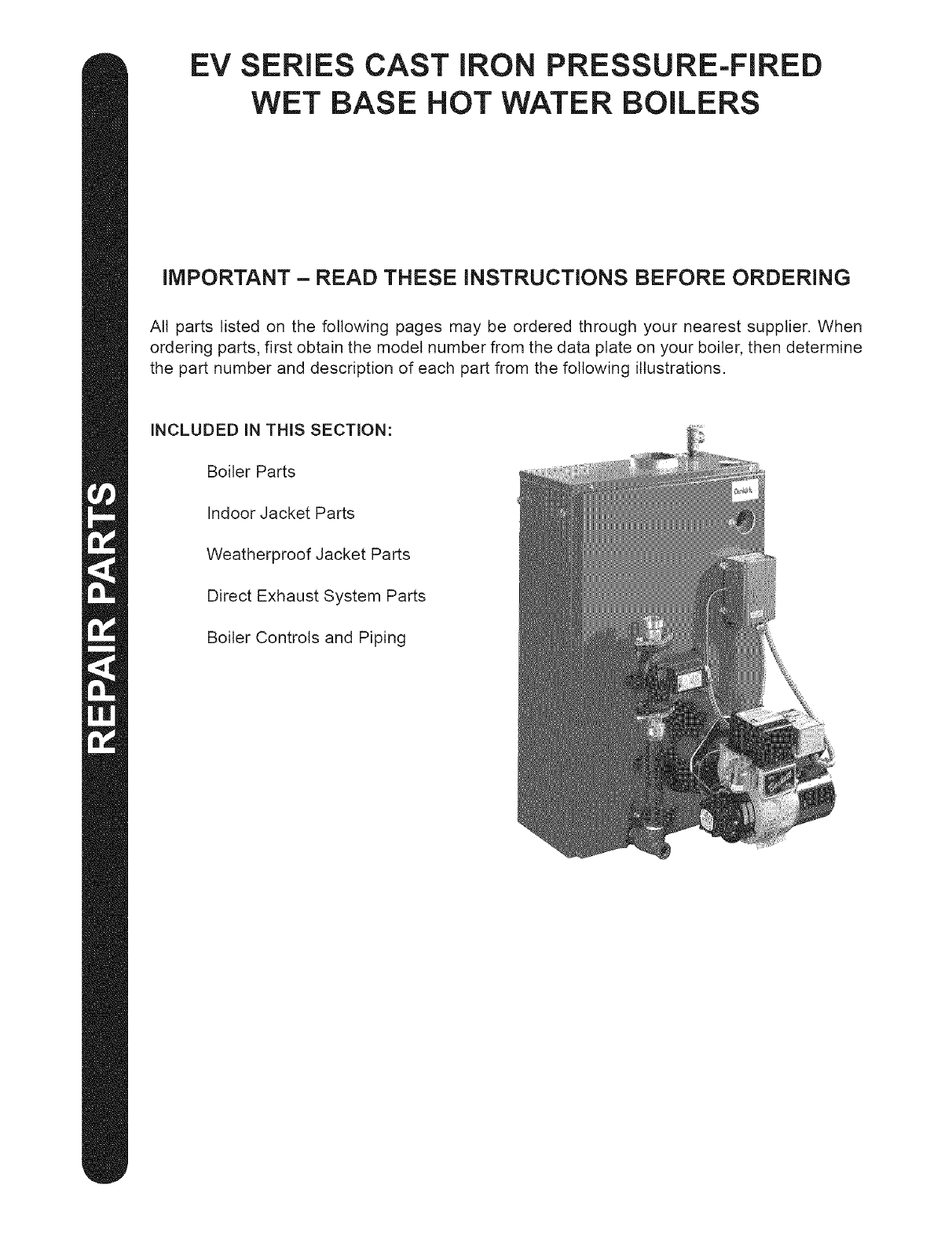
EV SERIES CAST IRON PRESSURE-FIRED
WET BASE HOT WATER BOILERS
IMPORTANT - READ THESE INSTRUCTIONS BEFORE ORDERING
All parts listed on the following pages may be ordered through your nearest supplier. When
ordering parts, first obtain the model number from the data plate on your boiler, then determine
the part number and description of each part from the following illustrations.
INCLUDED IN THIS SECTION:
Boiler Parts
Indoor Jacket Parts
Weatherproof Jacket Parts
Direct Exhaust System Parts
Boiler Controls and Piping
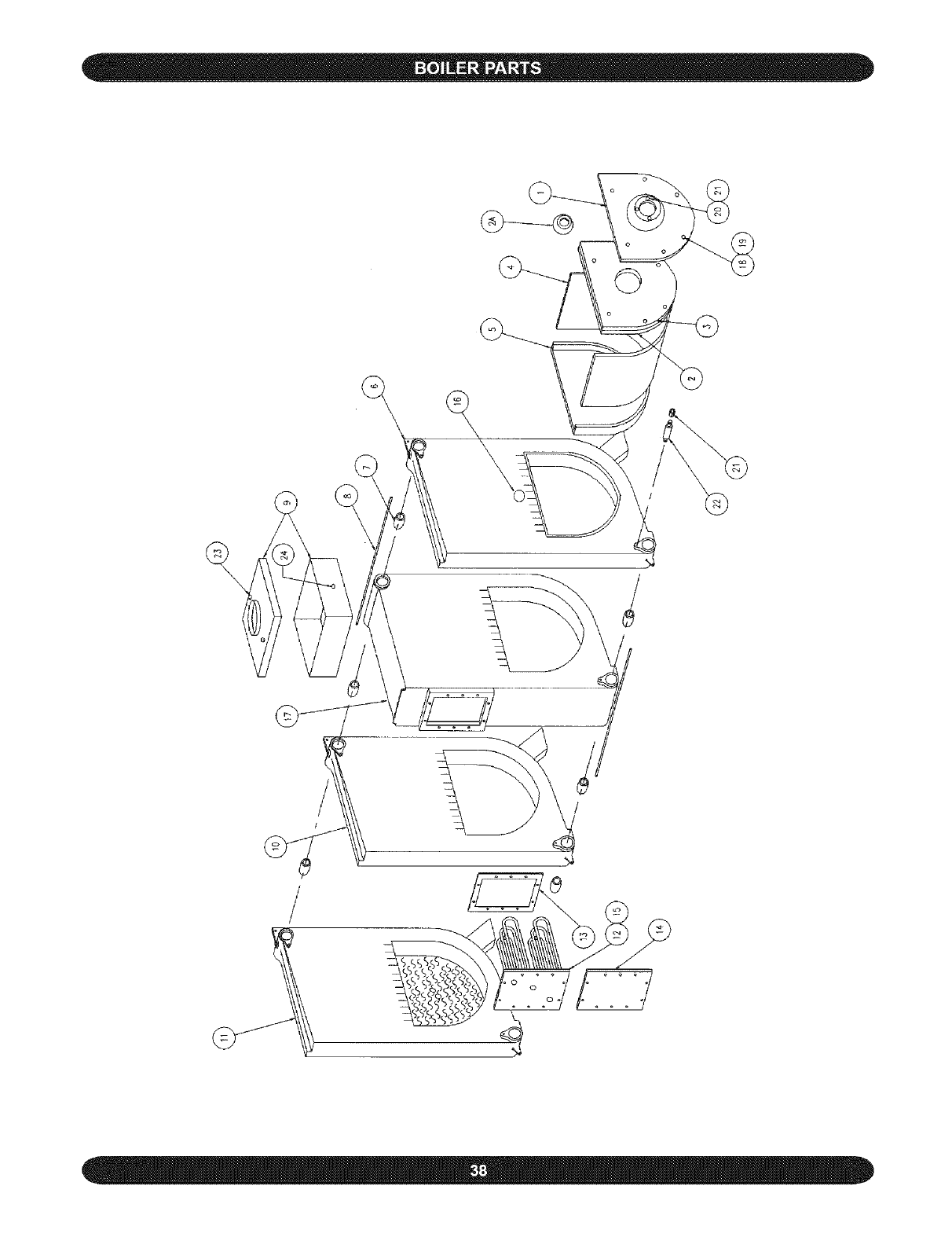
©
\
\
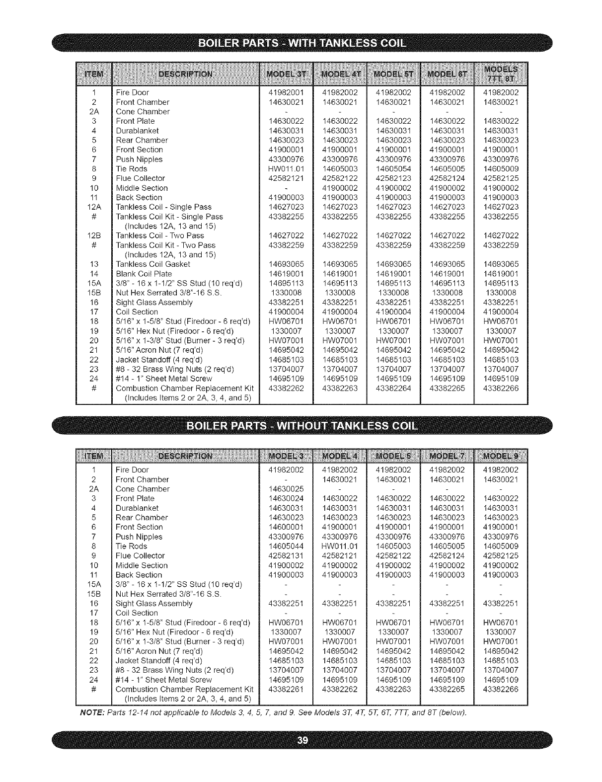
_Jii':;i:|_EMii;iiiii
I
2
2A
3
4
5
6
7
8
9
I0
11
12A
#
I2B
#
I3
14
15A
I5B
I6
I7
I8
I9
20
21
22
23
24
#
Fire Door
Front Chamber
Cone Chamber
Front Plate
Durablanket
Rear Chamber
Front Section
Push Nipples
Tie Rods
Flue Collector
Middle Section
Back Section
Tankless Coil - Single Pass
Tankless Coil Kit - Single Pass
(Includes 12A, 13 and 15)
Tankless Coil - Two Pass
Tankless Coil Kit - Two Pass
(Includes 12A, 13 and I5)
Tankless Coil Gasket
Blank Coi! Plate
318"- 16 x 1-1/2" SS Stud (10 req'd)
Nut Hex Serrated 3/8"-16 S.S.
Sight Glass Assembly
Coil Section
5/16" x 1-5/8" Stud (Firedoor - 6 req'd)
5/16" Hex Nut (Firedoor - 6 req'd)
5/16" x 1-3/8" Stud (Burner - 3 req'd)
5/16" Acron Nut (7 req_d)
Jacket Standoff (4 req_d)
#8 - 32 Brass Wing Nuts (2 req'd)
#14 - 1" Sheet Metal Screw
Combustion Chamber Replacement Kit
(Includes Items 2 or 2A, 3, 4, and 5)
41982001
14630021
14630022
14630031
14630023
41900001
43300976
HW011.01
42582121
41900003
14627023
43382255
14627022
43382259
14693065
14619001
14695113
1330008
43382251
41900004
HW06701
1330007
HW07001
14695042
14685103
13704007
14695109
43382262
41982002
14630021
14630022
14630031
14630023
41900001
43300976
14605003
42582122
41900002
41900003
14627023
43382255
14627022
43382259
14693065
14619001
14695113
1330008
43382251
41900004
HW06701
1330007
HW0700I
14695042
14685103
13704007
14695109
43382263
41982002
14630021
14630022
14630031
14630023
41900001
43300976
14605054
42582123
41900002
41900003
14627023
43382255
14627022
43382259
14693065
14619001
14695113
1330008
43382251
41900004
HW06701
1330007
HW07001
14695042
14685103
13704007
14695109
43382264
41982002
14630021
14630022
14630031
14630023
41900001
43300976
14605005
42582124
41900002
41900003
14627023
43382255
14627022
43382259
14693065
14619001
14695113
1330008
43382251
41900004
HW06701
1330007
HW0700I
14695042
14685103
13704007
14695109
43382265
41982002
14630021
14630022
14630031
14630023
41900001
43300976
14605009
42582125
41900002
41900003
14627023
43382255
14627022
43382259
14693065
14619001
14695113
1330008
43382251
41900004
HW06701
1330007
HW07001
14695042
14685103
13704007
14695109
43382266
I
2
2A
3
4
5
6
7
8
9
10
11
I5A
I5B
16
17
18
19
20
21
22
23
24
#
Fire Door
Front Chamber
Cone Chamber
Front Plate
Durablanket
Rear Chamber
Front Section
Push Nipples
Tie Rods
Flue Collector
Middle Section
Back Section
M EL:3
41982002
14630025
14630024
14630031
14630023
14600001
43300976
14605044
42582131
41900002
41900003
41982002
14630021
14630022
14630031
14630023
41900001
43300976
HW011.01
42582121
41900002
41900003
41982002
14630021
14630022
14630031
14630023
41900001
43300976
14605003
42582122
41900002
41900003
41982002
14630021
14630022
14630031
14630023
41900001
43300976
14605005
42582124
41900002
41900003
3/8" - 16 x 1-1/2" SS Stud (10 req_d)
Nut Hex Serrated 3/8"-16 S.S.
Sight Glass Assembly
Coil Section
5/16" x 1-5/8" Stud (Firedoor - 6 req'd)
5/16" Hex Nut (Firedoor - 6 req_d)
5/16" x 1-3/8" Stud (Burner - 3 req'd)
5/16"Acron Nut (7 req'd)
Jacket Standoff (4 req'd)
#8 - 32 Brass Wing Nuts (2 req'd)
#14 - 1" Sheet Metal Screw
Combustion Chamber Replacement Kit
(Includes Items 2 or 2A, 3, 4, and 5)
43382251
HW06701
1330007
HW07001
14695042
14685103
13704007
14695109
43382261
43382251
HW06701
1330007
HW07001
14695042
14685103
13704007
14695109
43382262
43382251
HW06701
1330007
HW07001
14695042
14685103
13704007
14695109
43382263
43382251
HW06701
1330007
HW07001
14695042
14685103
13704007
14695109
43382265
NOTE: Parts 12-14 not applicable to Models 3, 4, 5, 7, and 9. See Models 3T, 4T, 5T, 6T, 7TT, and 8T (below).
41982002
14630021
14630022
14630031
14630023
41900001
43300976
14605009
42582125
41900002
41900003
43382251
HW06701
1330007
HW07001
14695042
14685103
13704007
14695109
43382266
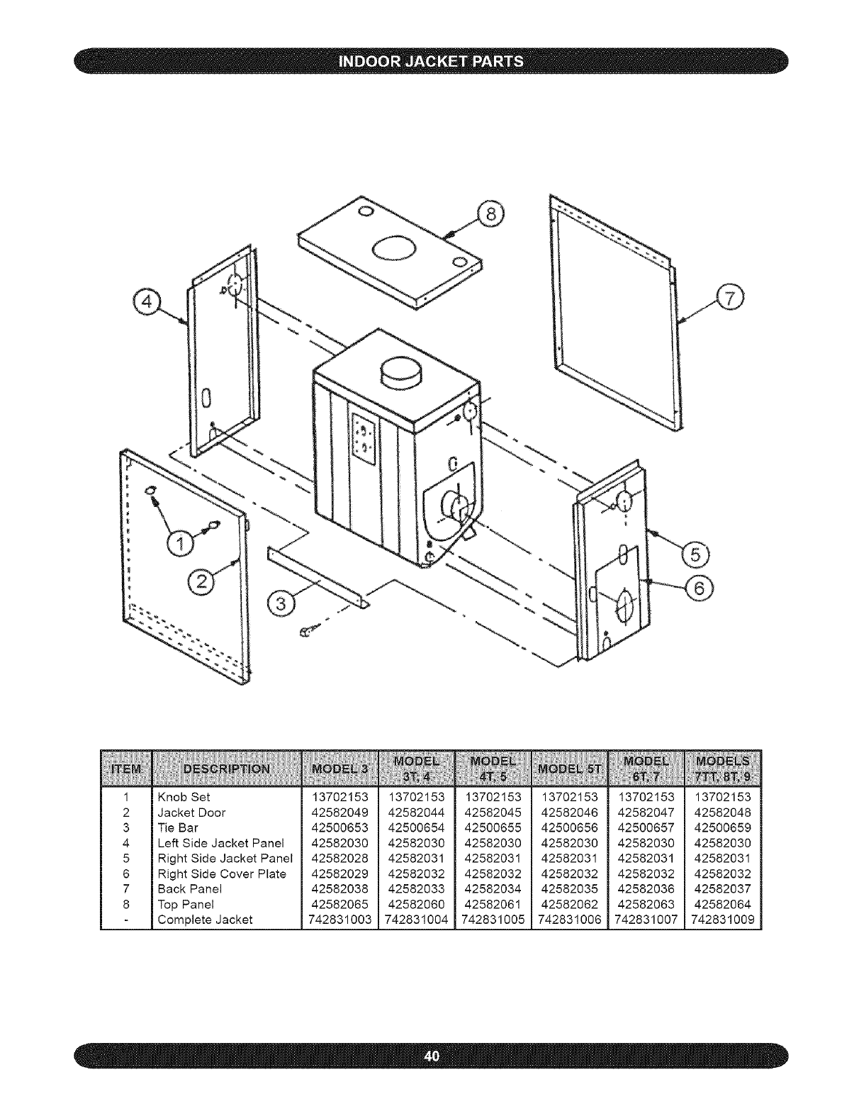
1
2
3
4
5
6
7
8
KnobSet
JacketDoor
TieBar
LeftSideJacketPanel
RightSideJacketPanel
RightSideCoverPlate
BackPanel
TopPanel
CompleteJacket
13702153
42582049
42500653
42582030
42582028
42582029
42582038
42582065
742831003
13702153
42582044
42500654
42582030
42582031
42582032
42582033
42582060
742831004
13702153
42582045
42500655
42582030
42582031
42582032
42582034
42582061
742831005
13702153
42582046
42500656
42582030
42582031
42582032
42582035
42582062
742831006
13702153
42582047
42500657
42582030
42582031
42582032
42582036
42582063
742831007
13702153
42582048
42500659
42582030
42582031
42582032
42582037
42582064
742831009
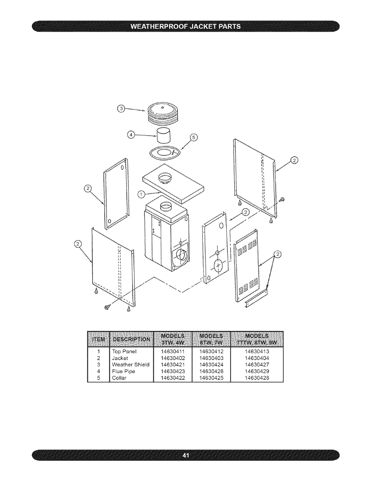
il
li
1 Top Panel 14630411 14630412 14630413
2 Jacket 14630402 14630403 14630404
3 Weather Shield 14630421 14630424 14630427
4 Flue Pipe 14630423 14630426 14630429
5 Collar 14630422 14630425 14630428
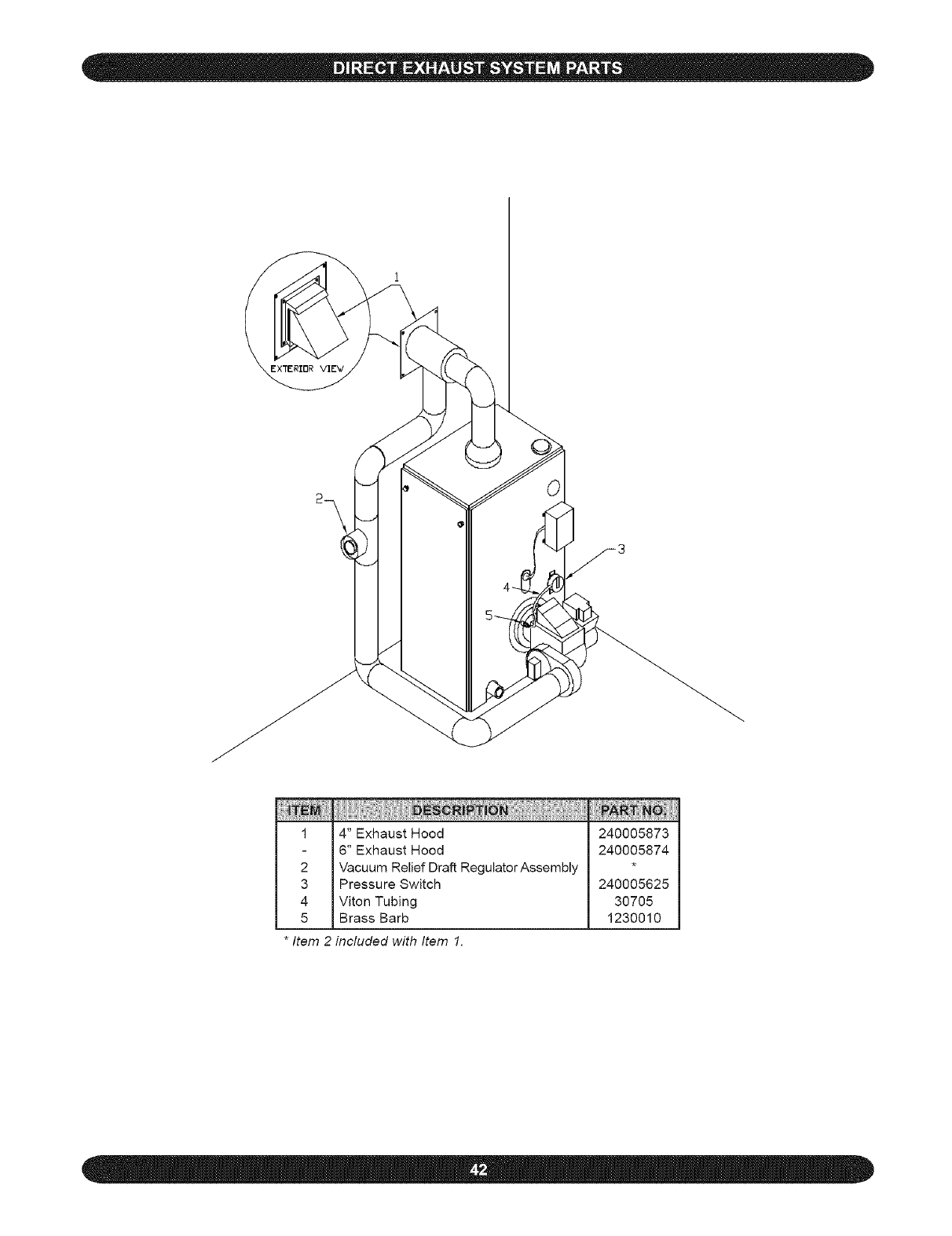
m
1
2
3
4
5
4" Exhaust Hood
6" Exhaust Hood
Vacuum Relief Draft RegulatorAssembly
Pressure Switch
Viton Tubing
Brass Barb
240005873
240005874
240005625
30705
1230010
*Item 2 included with Item 1.
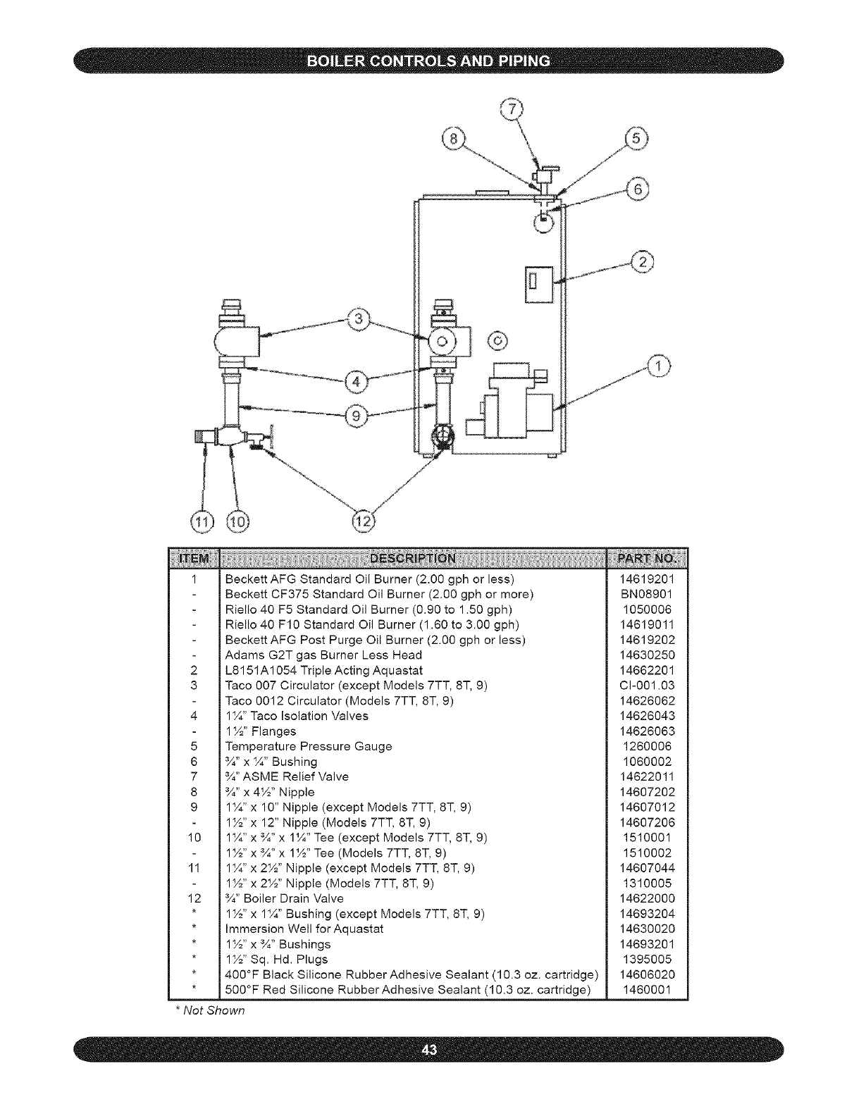
1
2
3
4
5
6
7
8
9
10
11
12
i i i
Beckett AFG Standard Oil Burner (2.00 gph or less)
Beckett CF375 Standard Oil Burner (2.00 gph or more)
Riello 40 F5 Standard Oil Burner (0.90 to 1.50 gph)
Riello 40 F10 Standard Oil Burner (1.60 to 3.00 gph)
Beckett AFG Post Purge Oil Burner (2.00 gph or less)
Adams G2T gas Burner Less Head
L8151A1054 Triple Acting Aquastat
Taco 007 Circulator (except Models 7TT, 8T, 9)
Taco 0012 Circulator (Models 7TT, 8T, 9)
14¼, Taco Isolation Valves
1%" Flanges
Temperature Pressure Gauge
¾" x 4¼,,Bushing
¾" ASME Relief Valve
¾" x 4%" Nipple
14¼,,x 10" Nipple (except Models 7TT, 8T, 9)
1%" x 12" Nipple (Models 7TT, 8T, 9)
14¼,,x ¾" x 1 ¼" Tee (except Models 7TT, 8T, 9)
1%" x ¾" x 1%" Tee (Models 7TT, ST, 9)
14¼"x 2%" Nipple (except Models 7TT, 8-i, 9)
1%"x 2%" Nipple (Models 7TT, 8T, 9)
¾" Boiler Drain Valve
1%"x 14¼', Bushing (except Models 7TT, 8T, 9)
Immersion Well for Aquastat
1%" x ¾" Bushings
1%" Sq. Hd. Plugs
400°F Black Silicone Rubber Adhesive Sealant (10.3 oz. cartridge)
500°F Red Silicone Rubber Adhesive Sealant (10.3 oz. cartridge)
*Not Shown
iiii(!i ii! iill
14619201
BN08901
1050006
14619011
14619202
14630250
14662201
Cl-001.03
14626062
14626043
14626063
1260006
1060002
14622011
14607202
14607012
14607206
1510001
1510002
14607044
1310005
14622000
14693204
14630020
14693201
1395005
14606020
1460001
