DZH C201 Bluetooth TouchPad Keyboard User Manual
Shenzhen DZH industrial Co., Ltd Bluetooth TouchPad Keyboard
DZH >
User manual

1
Product Specifications
P
PP
Portable Slim
ortable Slimortable Slim
ortable Slim Type
Type Type
Type
T
TT
Touchpad
ouchpad ouchpad
ouchpad K
KK
Keyboard
eyboardeyboard
eyboard
Model
ModelModel
Model:
::
:C201
C201C201
C201
Shenzhen
ShenzhenShenzhen
Shenzhen Dezhongheng Industry Co.,Ltd
Dezhongheng Industry Co.,Ltd Dezhongheng Industry Co.,Ltd
Dezhongheng Industry Co.,Ltd

2
目
目目
目
錄
錄錄
錄
1、
、、
、Scope
1.1 Summary ……………………………………………………………………………………………… 3
1.2 Bluetooth Device ……………………………………………………………………………………… 3
1.3 Color of Appearance ………………………………………………………………………………… 3
1.4 USB Charge Cable …………………………………………………………………………………… 3
1.5 System Requirement ………………………………………………………………………………… 4
2
22
2、
、、
、M
MM
Mechanism
echanismechanism
echanism
……
…………
………………………………………………………………………………………………
……………………………………………………………………………………………………………………………………………………………………………………
…………………………………………………………………………………………
4
2.1 Key Structure …………………………………………………………………………………………… 4
2.2 Materials ………………………………………………………………………………………………… 4
2.3 Lifetime of Key ………………………………………………………………………………………… 4
2.4 Pressure Curve of Key Strike ………………………………………………………………………… 5
3
33
3、
、、
、Functions and Electronic Specifications
Functions and Electronic Specifications Functions and Electronic Specifications
Functions and Electronic Specifications ……………………………………………
…………………………………………………………………………………………
…………………………………………………………
…………………………
……………
5
3.1 Functions ……………………………………………………………………………………………… 5
3.2 Sleep State …………………………………………………………………………………………… 5
3.3 LED Indicator ………………………………………………………………………………………… 6
3.4 Temperature Conditions ……………………………………………………………………………… 6
4
44
4、
、、
、E
EE
Environment
nvironmentnvironment
nvironment Test
Test Test
Test ……………………………………………………………………………………… 7
4.1 Non-operating Low Temperature and Humidity Test ……………………………………………… 7
4.2 Non-operating High Temperature and High Humidity Test
……………………………………… 7
4.3 Non-operation High / Low Temperature with Humidity Loop Test ……………………………… 7
5
55
5、
、、
、Vibration Test
Vibration TestVibration Test
Vibration Test …………………………………………………………………………………………… 8
6
66
6、
、、
、O
OO
Outward
utward utward
utward A
AA
Appearance
ppearanceppearance
ppearance
………………………………………………………………………………… 9
3
1、
、、
、Scope
1.1 Summary
This specification defines the product: a Bluetooth device using the HID Protocol, with
keyboard and touchpad features of an input device can do for personal computer, tablet
computer, notebook computer and smart phone.
Language:US
Key Number:76 Keys
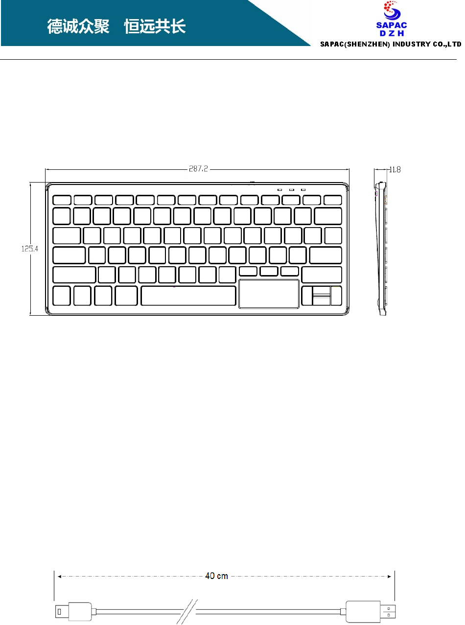
Dimensions:287.2 x 125.4 x 11.8 mm
Touchpad Dimensions:55.3 x 26.1 mm
Net Weight:223±5 gm
1.2 Bluetooth Device
Bluetooth devices using the HID Protocol, version: 3
1.3 Color of Appearance
Black, white or customized
1.4 USB Charge Cable
Length:40 cm ±10%
4
1.5 System Requirement
‧ iOS 4.0 or later
‧ iMac 10.6 or later
‧ Android® 3.0or later
‧ Windows® XP、Windows® 7、Windows® 8 or later
2、
、、
、Mechanism
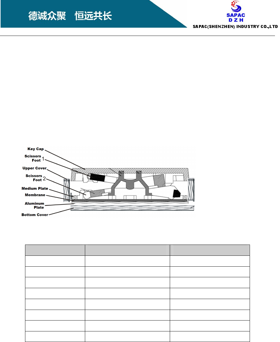
2.1 Key Structure
2.2 Materials
Component Name Material UL Authentication
Upper Cover ABS 94HB
Key Cap ABS 94HB
Medium Plate ABS 94HB
Membrane PET 94VTM-2
Silicone Silicone 94HB
Scissors Foot POM 94HB
Metal Plate AL / Secc
Bottom Cover ABS 94HB
2.3 Lifetime of Key
5,000,000 Times or above
5
2.4
2.42.4
2.4
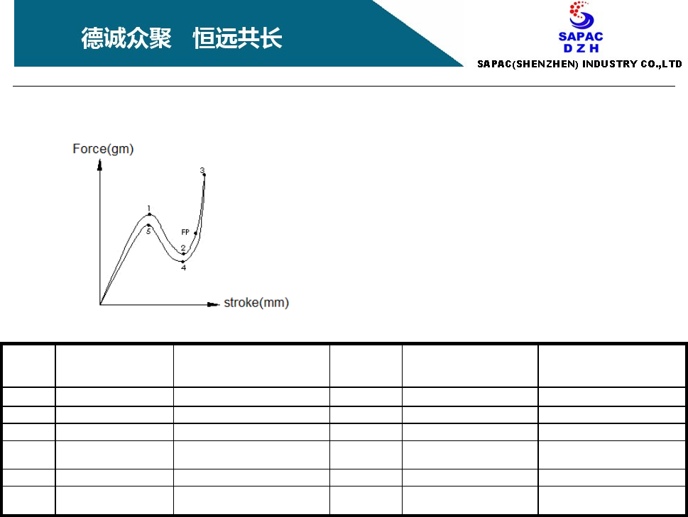
Pressure Curve of Key Strike
Point
Position(mm)
Initial
Position (mm)
After 10 millions (normal)
After 3 millions (fn)
Force
(Mark)
Force (g)
Initial
Force (g)
After 10 millions (normal)
After 3 millions (fn)
1 S1 =0.9 ± 0.40 S1 =0.9 ± 0.60 PF 65 ± 20 g (PF) 65 +20/-30 g
2 S2 =1.7 ± 0.40 S2 =1.7 ± 0.60 CL P1(F)-P2(F)≧20 g N/A
3 S6 =2.25± 0.30 S6 =2.25 ± 0.60 TM Max 150 g N/A
4 S3 =P2 ± 0.40 S3 =P2 ± 0.60 RF Min 15 g (RF) Min 10 g (normal key)
Min 5 g (fn key)
5 S4 = (N/A) S4-- (N/A) RP RP/PF≧0.75 N/A
Fire
point
S5=P2+0.35/0.0 S5-- (N/A) FP F2~F2+15g N/A
Mark statement:
PF=Peak force CL=Click feeling, 點擊力
TM=Travel to make RF=Return force, 返回力
RP= Return point (hysteresis) FP= Fire point 擊發點
3、
、、
、Function and Electronic Specifications
3.1 Function Specifications
Bluetooth Air-Link : 9 Meters (Straight Line without Obstacles)
Pairing Memory Switch: 3 Locations
Pairing Change Steps: After the power is off, select the Location of the Pairing Memory
Switch, and then back on.
Touchpad Resolution: 512 DPI
Rechargeable Battery Capacity: 370 mA/H
Battery Recharging Cycle Life: 500 Cycles @ 25℃
Battery Charge-Speed: 0.3C
Battery Operating Time: After charging is completed, more than 40 hours of continuous use.

6
Battery Standby Time: After charging is completed, standby time of up to 6 months or more
3.2 Sleep State
Keyboard after about 30 minutes in idle state into Sleep-State, press any key of the
keyboard can wake up the keyboard.
3.3 LED Indicator
Caps Lock LED:
::
:
。 LED illuminated indicates Keyboard lock the key in capital letters.
。 Keyboard in Sleep-Mode, The Caps Lock LED turns off.
Bluetooth Status LED:
::
:
。 Bluetooth device in pairing mode, LED flashes.
。 After the Bluetooth device in the link is complete, LED is off.
。 When Bluetooth device in the link-back status, the LED flashes quickly.
Battery status indicator:
。 When battery power is low, the red LED is flashed.
。 During charging, the Green LED is lit.
。 When charging is complete, the Green LED goes out.
3.4 Temperature Conditions
Operating Temperature: 0℃
℃℃
℃ ~ 40℃
℃℃
℃ (max.)
Storage Temperature: -20℃
℃℃
℃ ~ 25℃
℃℃
℃

7
4、
、、
、Environment Test
The product via the following environment test requirements.
4.1 Non-operating Low Temperature and Humidity Test
Test Conditions:At the temperature of -25℃~25℃, sample initially at 25 ℃ test environment
(humidity is about 25%).
1) Temperature gradually drop to -25℃, the time interval is 3 hours.
2) Under the condition of -25℃, the time interval is 10 hours.
3) Temperature gradually rises to 25℃, the time interval is 3 hours.
4) Remain under the conditions of 25 ℃, the time interval is 10 hours
5) Repeat step 1) ~ step 4), the time interval of 156 hours.
4.2 Non-operating High Temperature and High Humidity Test
Test conditions: At 40℃ - 95% humidity (non-condensing) and climate change rate of about 20%
per hour in test environment
1) At the beginning, sample under low temperature of 25℃ with lower humidity (about 20%)
environment.
2) Set the temperature gradually rose to 40 ℃, time interval of 2 hours.
3) Humidity gradually rose to 95%, the interval is 3.5 hours.
4) Under 40 ℃ and 95% humidity conditions, sample placed for 24 hours
5) Humidity gradually lowered (25% rate of change per hour), the time interval is 3.5 hours.
6) Gradually reducing the temperature to 25 ℃, the time interval is 2 hours
7) Repeat the above steps to test the sample
4.3 Non-operation High / Low Temperature with Humidity Loop Test
The purpose of this test is used to detect the impact of temperature and humidity for plastic
covers and the printing on Keys, and then provide the right solution.
Test method: the samples placed in low humidity environment in turn the cooled-compartment
(-20℃) and the heat-compartment (60℃) for 2 hours each, and repeat the cycle
lasts 48 hours test time.
1) The samples were placed in the first compartment.
2) The temperature of the second compartment were set to -20℃.
3) After the cold-compartment temperature stability, the samples placed into for 2 hours.
4) Set the temperature of a compartment as a hot cabin (60℃ )
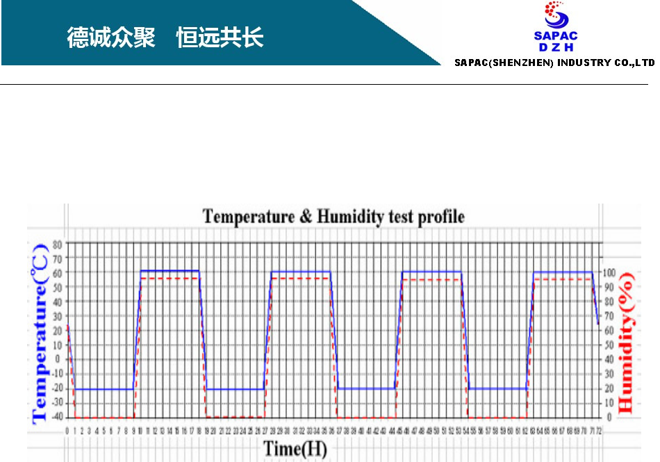
8
5) Test sample placed in the cold-compartment for 2 hours, then placed the samples into a
heat-compartment for 2 hours; repeated in turn the sample placed in the
cold-compartment and the heat-compartment for 2 hours each. After test time-up to 48
hours, the test sample has been relocated in a room temperature environment.
After all the end of the test, test samples must pass the following test.
1. Trip switch position measurement and function measurement.
2. Keys measure - pressing a key with your finger on the middle and edges, check keys.
3. Plastic deformation of the keyboard check.
4. The contact-resistance of keys must less than 500Ω.
5. Check the key letter printing.
5、
、、
、 Vibration Test
。 Test Environments 22℃ 75%(RH)
。 Package 20pcs/carton
。 Sweep Frequency 10-55-10Hz/minutes
。 Amplitude of vibration 76 cm
。 Orientation Vibration Each of X, Y, Z direction vibration tests for 1 hour
9
6、
、、
、Outward Appearance
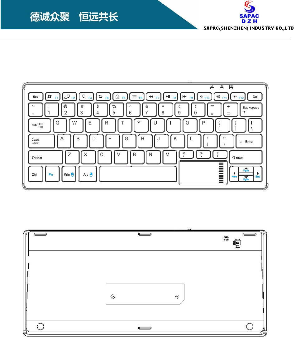
Front Side (US)
Back Side
Federal Communication Commission Interference Statement
This equipment has been tested and found to comply with the limits for a Class B digital device, pursuant
to Part 15 of the FCC Rules. These limits are designed to provide reasonable protection against harmful
interference in a residential installation. This equipment generates, uses, and can radiate radio frequency
energy and, if not installed and used in accordance with the instructions, may cause harmful interference
to radio communications. However, there is no guarantee that interference will not occur in a particular
installation. If this equipment does cause harmful interference to radio or television reception, which can
be determined by turning the equipment off and on, the user is encouraged to try to correct the
interference by one or more of the following measures:
• Reorient or relocate the receiving antenna.
• Increase the separation between the equipment and receiver.
• Connect the equipment into an outlet on a circuit different from that to which the receiver is connected.
• Consult the dealer or an experienced radio/TV technician for help.
FCC Caution:
This device complies with Part 15 of the FCC Rules. Operation is subject to the following two conditions:
(1) This device may not cause harmful interference, and (2) this device must accept any interference
received, including interference that may cause undesired operation.
Non-modification Statement:
Changes or modifications not expressly approved by the party responsible for compliance could void the user's
authority to operate the equipment.