Dacor Ewo Users Manual
MW to the manual 2a067f4b-337a-4852-9fbe-bc5de8e28ffe
2015-02-02
: Dacor Dacor-Ewo-Users-Manual-425100 dacor-ewo-users-manual-425100 dacor pdf
Open the PDF directly: View PDF ![]() .
.
Page Count: 2
PLANNING
GUIDE
Web: http://www.Dacor.com
Corporate Phone: 800-793-0093
Specifications are subject to change without notice.
See installation instructions for additional details. 2.1
24”, 27”, 30”, 36” Wide,
Warming Ovens
EW, EWO, MW, MWO, PW, & PWO
Warming Ovens
1/2
A
Warming Oven
Warming Oven
OB Outdoor Grill
EG Epicure Gas Cooktop
B
3/4" Min.
(19mm)
D
5/8" Min
.
(16mm)
120 Vac
electrical
outlet
36" typ.
(914mm)
C
C
Warming Oven
Cooktop
1 1/2" (38mm)
Typical countertop
3/4" Min.
(19mm)
5/8" Min.
(16mm)
120 Vac
electrical
outlet
A
36" Typ.
(914mm)
B
C
27"/30"/36"
Dacor
single oven
Warming Oven
Warming Oven
Toe Kick
1 ¾” Min.
(44mm)
5/8” Min.
(16mm)
D
C
C
A
120 Vac
electrical
outlets
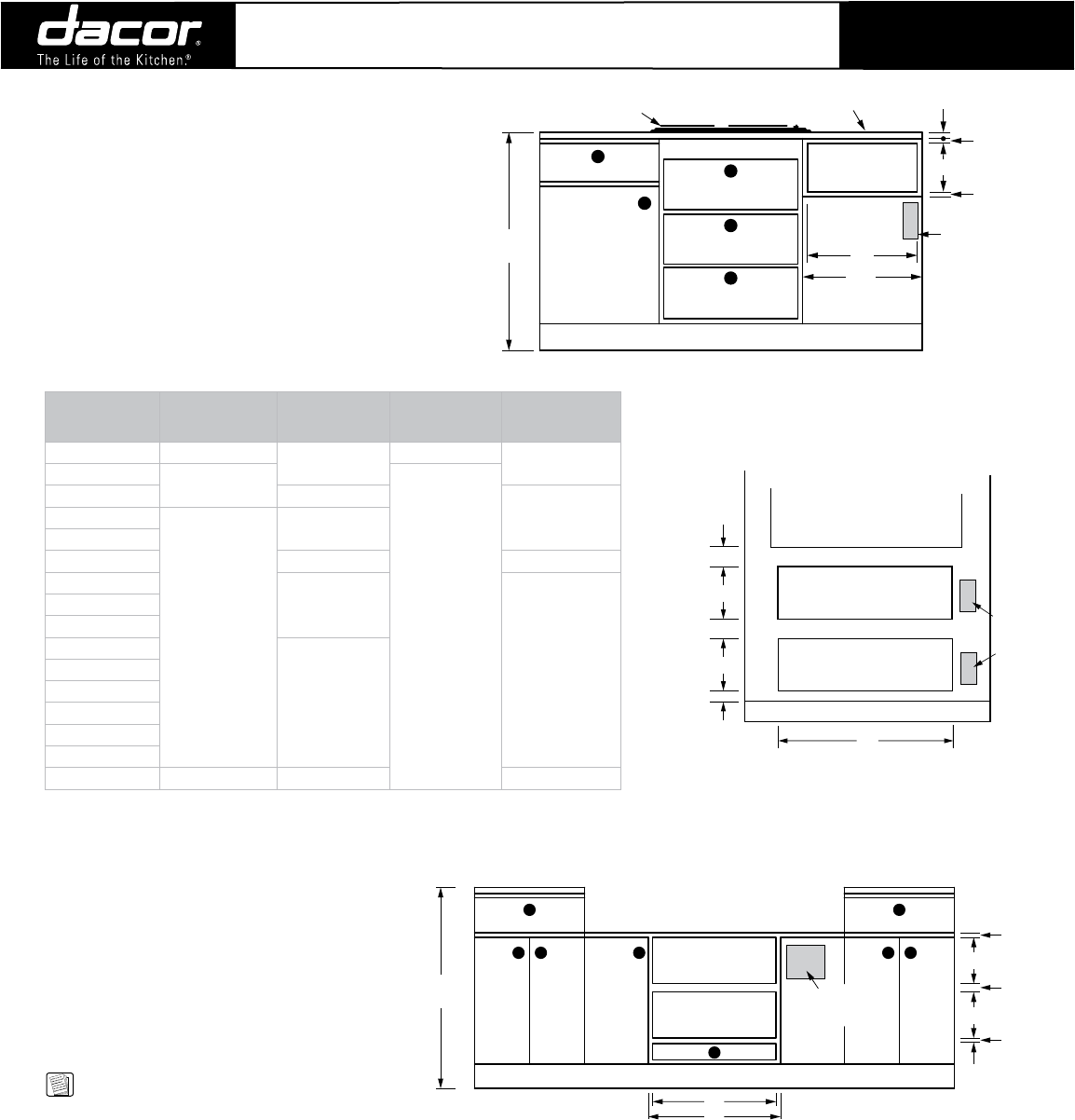
NOTES:
1. EWO36 models cannot be stacked.
2. 23 3/8” (594mm) minimum cabinet depth.
3. 3/4” (19mm) support platform (flush with cutout).
4. See the Combination Installation (CI) Section if
installing with a wall oven, microwave, or cooktop.
5. For stacked warming ovens, see CI.23.
Revised
12/21/07
CUTOUT DIMENSIONS
Model “A” Cutout Width
“B” Min. Width
to Adjacent
Doors/Drawers
“C” Cutout
Height
“D” Min. Gap
Between Cutouts
IOWO24 22 9/16” (573mm) N/A* 12 1/8” (308mm) N/A*
IWO24 22 1/2” (572mm)
9 1/8” (232mm)
EWO24 24 1/4” (616mm)
1 1/16” (27mm)EW27
25 1/2” (648mm)
27 1/4” (692mm)
EWO27
IWO27 N/A* N/A*
MW27
27 1/4” (692mm)
1 1/16” (27mm)
MWO27
PW27
EW30
30 1/4” (768mm)
EWO30
MW30
MWO30
PW30
PWO30
EWO36 34 3/8” (873mm) 36 1/4” (921mm 3” (76mm)
* Depends on size of cabinet face installed.
PLANNING
GUIDE
Web: http://www.Dacor.com
Corporate Phone: 800-793-0093
Specifications are subject to change without notice.
See installation instructions for additional details. 2.2
24”, 27”, 30”, 36” Wide,
Warming Ovens
EW, EWO, MW, MWO, PW, & PWO
Warming Ovens
2/2
Model
“C” Drawer Face
Width
“D” Chassis Face
Width
“E” Chassis
Width
EWO24 23 7/8” (606mm) 23 11/16” (602mm) 22 3/16” (564mm)
EW27
26 7/8” (683mm) 26 11/16” (678mm)
25 3/16” (640mm)
EWO27
MW27
MWO27
PW27
EW30
29 7/8” (759mm) 29 11/16” (754mm)
EWO30
MW30
MWO30
PW30
PWO30
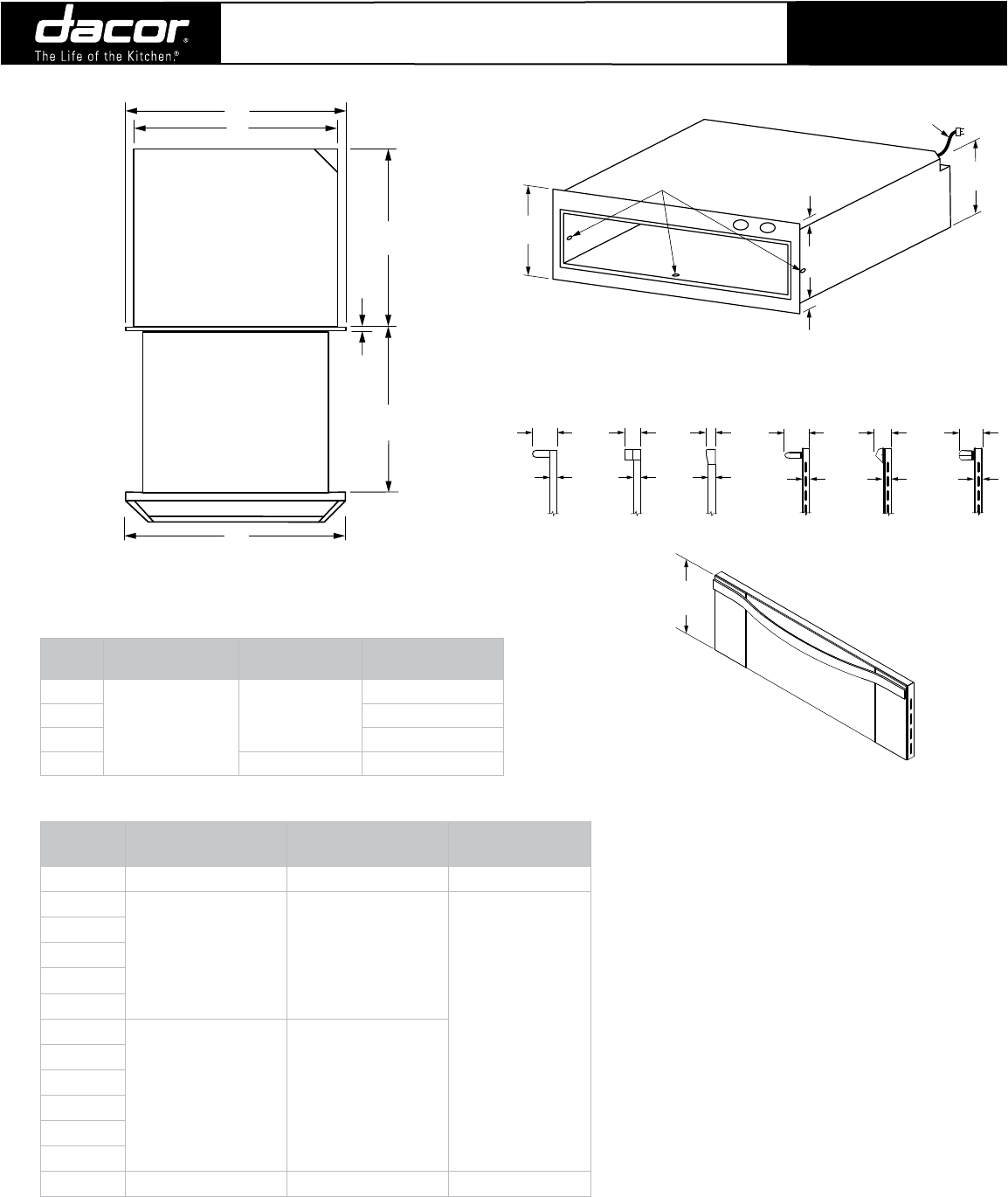
EWO36 35 7/8” (411mm) 35 11/16” (906mm) 34 1/4” (870mm)
OVERALL DIMENSIONS
TOP VIEW
(EWO Shown)
23 1/16"
(586mm)
Chassis
Drawer open
5/64"
(2mm)
23 13/16”
(605mm)
D
C
E
DRAWER FACE DIMENSIONS
(MW Shown)
10 1/8"
(257mm)
OVERALL ChASSIS DIMENSIONS
(Chassis View Without Drawer)
1/2"
(13mm)
1/2"
(13mm)
Chassis view
without drawer
Mounting
holes
40" (1016mm)
3 prong
120 Vac power cord
10"
(254mm)
9"
(229mm)
3 5/16"
(84mm)
1"
(25mm)
EWO
1"
(25mm)
1 5/16"
(33mm)
MWO
1"
(25mm)
2 3/16"
(56mm)
PWO
3 7/16"
(87mm)
EW
3 1/4"
(83mm)
PW
2 1/4"
(57mm)
MW
1"
(25mm)
1 5/32"
(29mm)
1 1/8"
(29mm)
SIDE VIEW hANDLE PROJECTIONS
Models
Dedicated Circuit
Required
Total Connected
Load
Approximate
Shipping Weight
24”
120VAC, 60Hz,
15A
(Breaker)
0.5kW (4A)
70 lbs.
27” 73 lbs.
30” 76 lbs.
36” 0.8kW (6.5A) 90 lbs.
Revised
11/29/07
