Dacor ERV48 User Manual VENT SYSTEM Manuals And Guides 1103298L
User Manual: Dacor ERV48 ERV48 DACOR VENT SYSTEM - Manuals and Guides View the owners manual for your DACOR VENT SYSTEM #ERV48. Home:Kitchen Appliance Parts:Dacor Parts:Dacor VENT SYSTEM Manual
Open the PDF directly: View PDF ![]() .
.
Page Count: 8
ERV AND PRV SERIES RAISED VENTS
DA R: Electric shock hazard! Before opening the access panels,
disconnect the power cord from the electrical outlet.
Tools Required
• Phillips head screwdriver ° Small set of side cutters
Flat blade screwdriver • Permanent marker
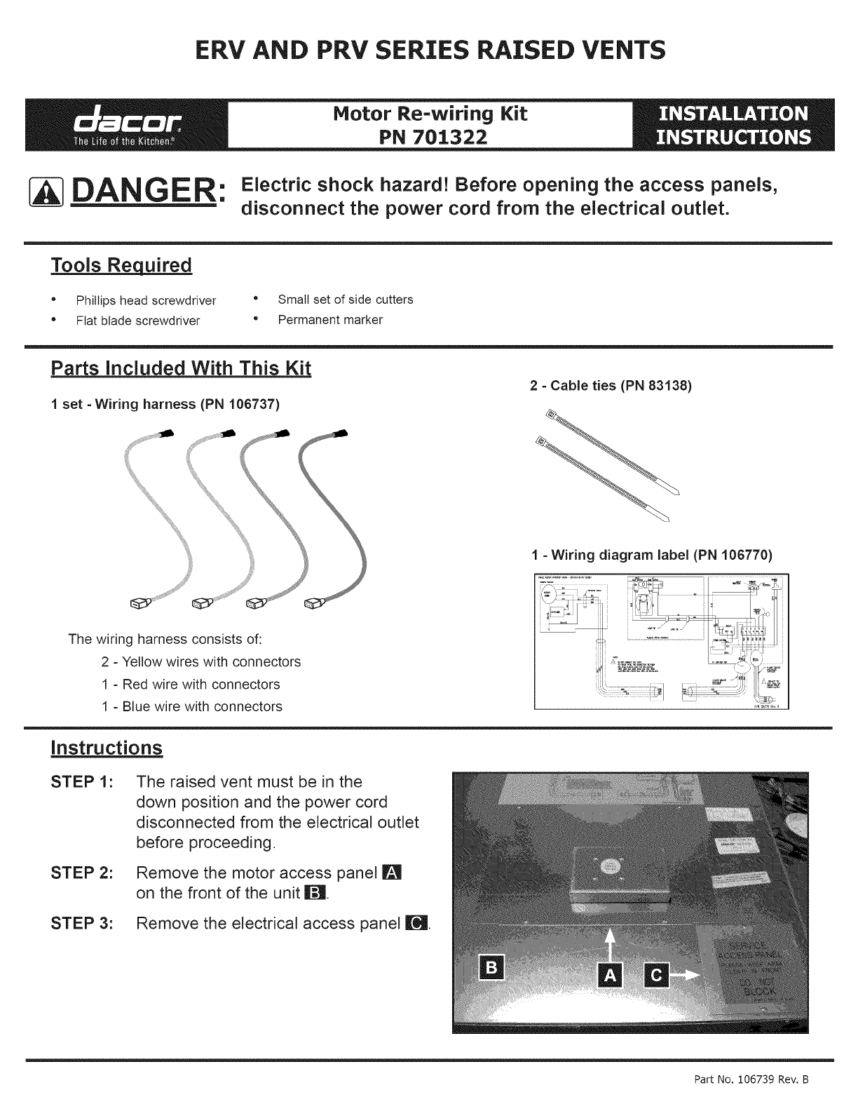
Parts Included With This Kit
2 - Cable ties (PN 83138)
1 set -Wiring harness (PN 106737)
The wiring harness consists of:
2 - Yellow wires with connectors
1 - Red wire with connectors
1 - Blue wire with connectors
Instructions
STEP 1:
STEP 2:
1 - Wiring diagram label (PN 106770)
STEP 3:
The raised vent must be in the
down position and the power cord
disconnected from the electrical outlet
before proceeding.
Remove the motor access panel I_
on the front of the unit i1_.
Remove the electrical access panel Ir_.
Part No, 106739 Rev, B

STEP 4:
STEP 5:
ERV/PRV Motor Wiring Kit Instructions
II
Using a flat blade screwdriver, loosen the screw for the left "NI" (POWER INPUT)
terminal _ inside the electrical access hole r_. rt is the fourth one down from the top
on the left side of the terminal block.
Remove the bJack and white wires [] from the terminal block. Separate the two wires
from each other.
STEP 6:
STEP 7:
Using a fiat blade screwdriver, pry off the clip _ that connects lifting arm i_l from
the motor assembly [] to the pin on the bottom of the plenum D (the plenum is the
portion of the vent that raises up when activated). Remove the lifting arm from the pin
on the plenum. Keep the clip for later use.
Inside the motor assembly compartment II, disconnect the red and blue wires _ on
the motor wiring harness.
Page 2
ERV/PRV Motor Wiring Kit Instructions
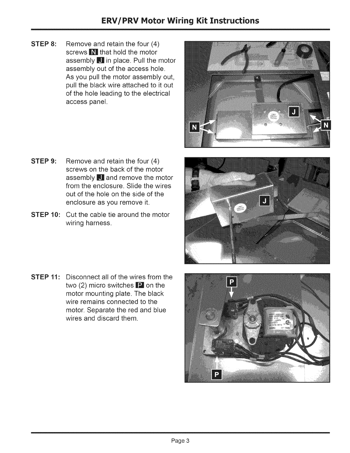
STEP 8: Remove and retain the four (4)
screws O that hold the motor
assembly iq in place. Pull the motor
assembly out of the access hole.
As you pull the motor assembly out,
pull the black wire attached to it out
of the hole leading to the electrical
access panel.
STEP 9:
STEP 10:
Remove and retain the four (4)
screws on the back of the motor
assembly m and remove the motor
from the enclosure. Slide the wires
out of the hole on the side of the
enclosure as you remove it.
Cut the cable tie around the motor
wiring harness.
STEP 11: Disconnect all of the wires from the
two (2) micro switches I_ on the
motor mounting plate. The black
wire remains connected to the
motor. Separate the red and blue
wires and discard them.
Page 3
ERV/PRV Motor Wiring Kit Instructions
[_ WARNING: Failure to connect the wiring harnesses as instructed may result in an electric
shock or fire hazard.
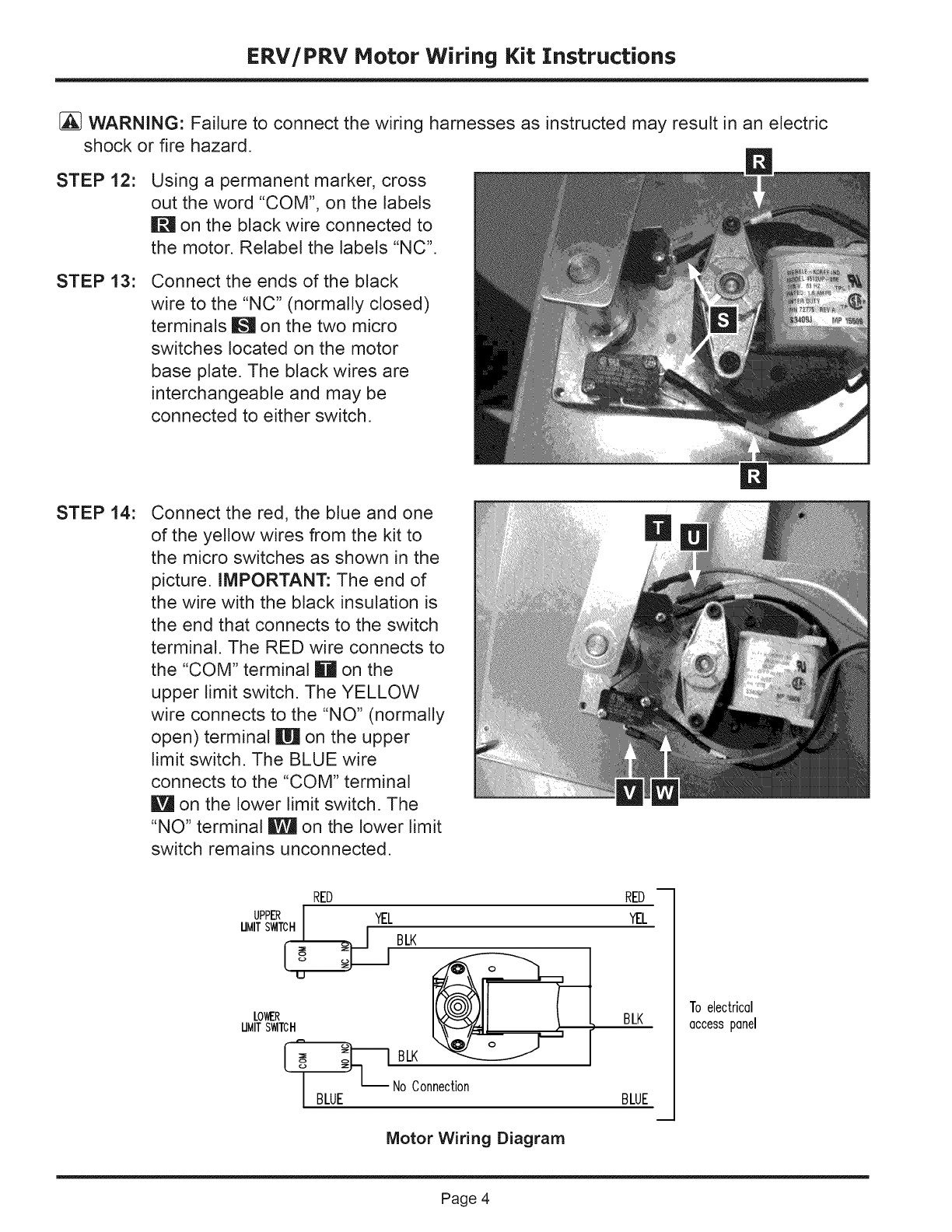
STEP 12: Using a permanent marker, cross
out the word "COM", on the labels
II_ on the black wire connected to
the motor. Relabel the labels "NC'.
STEP 13: Connect the ends of the black
wire to the "NC" (normally closed)
terminals ![_ on the two micro
switches located on the motor
base plate. The black wires are
interchangeable and may be
connected to either switch.
STEP 14: Connect the red, the blue and one
of the yellow wires from the kit to
the micro switches as shown in the
picture. IMPORTANT: The end of
the wire with the black insulation is
the end that connects to the switch
terminal. The RED wire connects to
the "COM" terminal Ill on the
upper limit switch. The YELLOW
wire connects to the "NO" (normally
open) terminal m on the upper
limit switch. The BLUE wire
connects to the "COM" terminal
I_ on the lower limit switch. The
"NO" terminal _ on the lower limit
switch remains unconnected.
RED
UPPER I YEL
UMITSWITCH
___ BLK
U
LOWER
UMITSWITCH
]_1 BLK
NoConnection
BLUE
Motor Wiring Diagram
RED
YEL
BLK
BLUE
m
To electricel
eccesspenel
Page 4
ERV/PRV Motor Wiring Kit Instructions
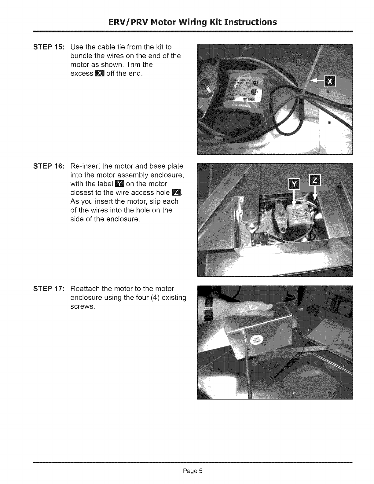
STEP 15: Use the cable tie from the kit to
bundle the wires on the end of the
motor as shown. Trim the
excess i_ off the end.
STEP 16: Re=insert the motor and base plate
into the motor assembly enclosure,
with the label !_ on the motor
closest to the wire access hole IM.
As you insert the motor, slip each
of the wires into the hole on the
side of the enclosure.
STEP 17: Reattach the motor to the motor
enclosure using the four (4) existing
screws.
Page 5
ERV/PRV Motor Wiring Kit Instructions
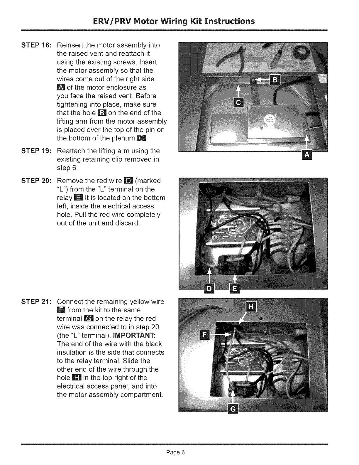
STEP 18:
STEP 19:
STEP 20:
Reinsert the motor assembly into
the raised vent and reattach it
using the existing screws. Insert
the motor assembly so that the
wires come out of the right side
I!_ of the motor enclosure as
you face the raised vent. Before
tightening into place, make sure
that the hole m on the end of the
lifting arm from the motor assembly
is placed over the top of the pin on
the bottom of the plenum I[_.
Reattach the lifting arm using the
existing retaining clip removed in
step 6.
Remove the red wire M (marked
"L") from the "L" terminal on the
relay it.It is located on the bottom
left, inside the electrical access
hole. Pull the red wire completely
out of the unit and discard.
STEP 21 :Connect the remaining yellow wire
I_ from the kit to the same
terminal I[_ on the relay the red
wire was connected to in step 20
(the "L" terminal). IMPORTANT:
The end of the wire with the black
insulation is the side that connects
to the relay terminal. Slide the
other end of the wire through the
hole Im in the top right of the
electrical access panel, and into
the motor assembly compartment.
Page 6
ERV/PRV Motor Wiring Kit Instructions
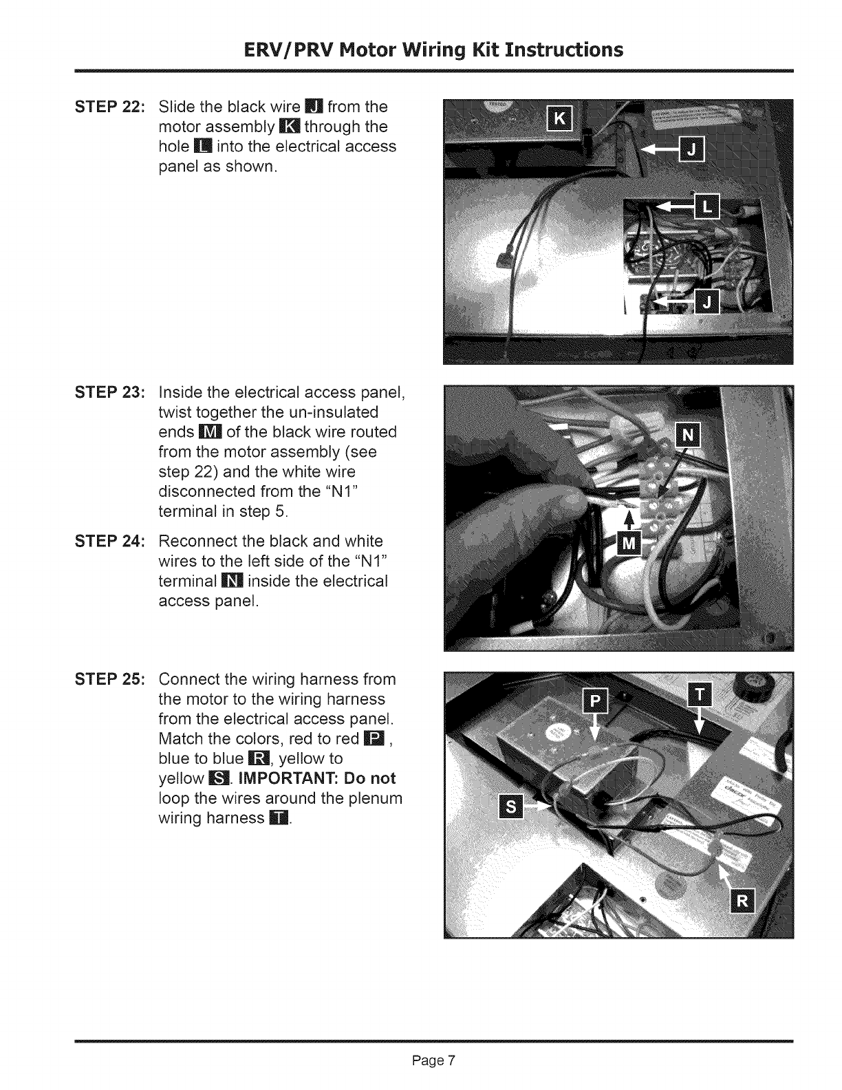
STEP 22: Slide the black wire n from the
motor assembly !1_ through the
hole m into the electrical access
panel as shown.
STEP 23:
STEP 24:
Inside the electrical access panel,
twist together the un-insulated
ends _ of the black wire routed
from the motor assembly (see
step 22) and the white wire
disconnected from the "NI"
terminal in step 5.
Reconnect the black and white
wires to the left side of the "NI"
terminal i_1 inside the electrical
access panel.
STEP 25: Connect the wiring harness from
the motor to the wiring harness
from the electrical access panel.
Match the colors, red to red Ill,
blue to blue i[_, yellow to
yellow I_--_.IMPORTANT: Do not
loop the wires around the plenum
wiring harness Ill.
Page 7

STEP 26:
STEP 27:
Use the remaining cable tie
from the kit, bundle the wiring
harnesses and stow them under
the right edge of the access
hole, away from the moving parts
toward the center of the unit.
Re-attach both access panels
using the existing screws.
STEP 28: Peel the backing off of the wiring
diagram label included with the kit.
Affix it to the front of unit, over the
top of the existing label W21.
STEP 29:
STEP 30:
STEP 31 :
Reconnect the unit to the
electrical outlet. Make sure it is
in the upright position for proper
operation. Test the unit as outlined
in the following steps.
Push the switch on top of the
unit. The vent should rise while
the blower remains off. Once the
vent is in its highest position, the
blower should come on.
Push the switch on top of the unit
again. The blower should turn off
and remain off as the vent lowers.
The Life of the Kitchen?
Dacor • Phone: (800) 793-0093 • FAX: (626)403-3130 • www.Dacor.com
