Daewoo Precision RK950NAR Remote Keyless Entry System (Receiver) User Manual DPI Instruction Manual
Daewoo Precision Industries Ltd Remote Keyless Entry System (Receiver) DPI Instruction Manual
Users Manual

DPI Remote Keyless Entry System
TECHNICAL SPECIFICATION
ORIGINATING CENTER: DPI TECHNICAL CENTER
FILENAME: RKE_RECEIVER.doc
REVISION NO.: A0
DATE: 10 / Nov / 2003
BAN DONG HOON
THCHNICAL CENTER:
Phone: 082 - (0)51 – 509 – 2287
Fax: 082 - (0)51 – 508 - 3994

R&D / Automotive Electronics
Title Remote Keyless Entry System Specification Spec. No. DPE-AE-RK019912S
Written by Ban Dong Hoon Rev. No. A0
Date 10th . Nov. 2003 Page 2 / 25
TABLE OF CONTENTS
1. INTRODUCTION...............................................................................................................4
1.1 REMOTE KEYLESS ENTRY FUNCTION ........................................................................4
1.2 ANTI-THEFT FUNCTION ..................................................................................................4
2. System Description..............................................................................................................5
3. RKE FUNCTION................................................................................................................7
3.1 DOOR LOCK / UNLOCK USING TRANSMITTER..........................................................7
3.1.1 TRANSMITTER LOCK / UNLOCK ...................................................................................7
3.1.2 TRANSMITTER DOOR / TRUNK......................................................................................8
3.2 BURGLAR ALARM ............................................................................................................9
3.3 DISARMING BY KEY CYLINDER .................................................................................10
3.4 SAFETY LOCK(AUTO DOOR LOCK AFTER 30SEC)..................................................11
3.5 SECURITY INDICATOR ..................................................................................................11
3.6 DIAGNOSTIC ....................................................................................................................11
3.7 ACTIVE RANGE ...............................................................................................................11
4. SYSTEM CONFIGRATION ...........................................................................................13
4.1 RECEIVER .........................................................................................................................13
4.1.1 FUNCTION.........................................................................................................................13
4.1.2 ELECTRIC SPEC ...............................................................................................................13
4.1.3 METHOD OF CODING TRANSMITTER ........................................................................13
4.2 TRANSMITTER.................................................................................................................14
4.2.1 ELECTRIC SPEC ...............................................................................................................14
4.2.2 DATA FORMATION.........................................................................................................14
4.2.3 TRANSMITTER FUNCTION............................................................................................15
4.2.4 BATTERY ..........................................................................................................................15
4.2.5 LED.....................................................................................................................................16
5. SYSTEM INPUT/OUTPUT CIRCUIT...........................................................................17
5.1.1 SERIAL DATA LINK(NO. A17).......................................................................................17
5.1.2 ELECTRIC OUTPUT.........................................................................................................17
5.1.2.1 HAZARD LAMP (LEFT : A26, RIGHT : A13).................................................................17
5.1.2.2 SECURITY INDICATOR(A19).........................................................................................17
5.1.2.3 LOCK(A10) ........................................................................................................................17
5.1.2.4 UNLOCK(A11)...................................................................................................................17
5.1.2.5 2 STEP UNLOCK (A16, PROVISION).............................................................................18
5.1.2.6 SIREN(A1)..........................................................................................................................18
5.1.2.7 TRUNK RELEASE(A14)...................................................................................................18
5.1.3 ELECTRIC INPUT.............................................................................................................18
5.1.3.1 TRUNK KEY CYLINDER UNLOCK SWITCH INPUT(A4) ..........................................19
5.1.3.2 DDRIVER KEY CYLINDER LOCK SWITCH INPUT(A6) ............................................19
5.1.3.3 PASSENGER KEY Cylinder UNLOCK SWITCH INPUT(A22)......................................19
5.1.3.4 HOOD OPEN SWITCH INPUT(A7) .................................................................................19
5.1.3.5 TRUNK(TAIL GATE) OPEN SWITCH INPUT(A5)........................................................20
5.1.3.6 DOOR OPEN SWITCH INPUT(A8) .................................................................................20
5.1.3.7 IGNITION SWITCH INPUT(A15) ....................................................................................21
5.1.3.8 KEY REMINDER SWITCH INPUT(A18) ........................................................................21
5.1.3.9 DOOR LOCK MONITORING SWITCH INPUT(A9) ..................................................21
6. SIREN ................................................................................................................................22
6.1.1 ELECTRIC SPECIFICATION ...........................................................................................22
6.1.2 APPEARANCE DRAWING ..............................................................................................22
6.1.3 MEASURING METHOD...................................................................................................23
6.1.4 Internal Oscillating Circuit..................................................................................................23
6.1.5 MECHANICAL CHARACTERISTICS.............................................................................24

R&D / Automotive Electronics
Title Remote Keyless Entry System Specification Spec. No. DPE-AE-RK019912S
Written by Ban Dong Hoon Rev. No. A0
Date 10th . Nov. 2003 Page 3 / 25
6.1.6 Environment Test................................................................................................................24
Compliance Statement
THIS DEVICE COMPLIES WITH PART 15 OF THE FCC RULES
Operating is subject to the following two conditions; (1) this device may not cause
harmful interference, and (2) this device must accept ant interference received,
including interference that may cause undesired operation.
CAUTION: Changes or modifications not expressly approved by the part
responsible for compliance could void the user’s authority to operate the equipment.

R&D / Automotive Electronics
Title Remote Keyless Entry System Specification Spec. No. DPE-AE-RK019912S
Written by Ban Dong Hoon Rev. No. A0
Date 10th . Nov. 2003 Page 4 / 25
1. INTRODUCTION
This document is the technical specification of the remote keyless entry (RKE) System for the car
consisting of DPI (Daewoo Precision Industries,. LTD) receiver (RX), DPI transmitter (TX) and
siren.
The purpose of the DPI RKE system is to provide the remote control function and the anti-theft
function in which it is installed and to prevent it from being driven by unauthorized users. The
verification of the user authorization is done by using a remote control operation with the
security code.
The diagnosis of the RKE is realized by the ALDL-function modes. They are realized by the
ALDL test equipment. To avoid manipulation of the usage of the test equipment, especially the
use of the key coding procedure has to be protected against unauthorized use.
1.1 REMOTE KEYLESS ENTRY FUNCTION
remote keyless entry occur the follow function.
a. remote door lock / unlock
b. remote trunk Release
c. vehicle locator
d. dream-net communication
1.2 ANTI-THEFT FUNCTION
anti theft alarm system occurs the follow function.
a. burglar alarm
b. display the ATAS status using security indicator.
c. safety lock

R&D / Automotive Electronics
Title Remote Keyless Entry System Specification Spec. No. DPE-AE-RK019912S
Written by Ban Dong Hoon Rev. No. A0
Date 10th . Nov. 2003 Page 5 / 25
2. SYSTEM DESCRIPTION
The RKE system consist of
• maximum 5 of in-key type transmitter(TX)
• a security led for displaying the RKE state
• a siren for the alarm state
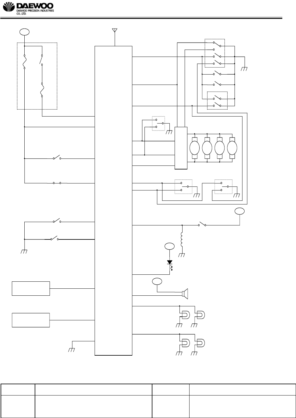
• Receiver control unit with
- power supply
- microprocessor
- EEPROM
- drivers for the external status led
- drivers for the external siren, flashing bulb and door lock relay unit
- drivers for the external trunk open actuator
- serial data link for communication with the test equipment
- ignition signal input circuit
- theft detection input circuit(door open, hood open, trunk open)
- key cylinder lock / unlock input circuit
- RF signal receiver
- RF signal receiving antenna
R&D / Automotive Electronics
Title Remote Keyless Entry System Specification Spec. No. DPE-AE-RK019912S
Written by Ban Dong Hoon Rev. No. A0
Date 10th . Nov. 2003 Page 6 / 25
[Figure 1. SYSTEM BLOCK DIAGRAM]
A12
A18
³»Àå TRUNK LID OPEN SW
TRUNK UNLOCK
A26
KEY INSERT
A5
RIGHT FLASHING BULB
COMMUNICATION LINE ( P )
UNLOCK
DOOR
LOCK
RELAY
B+
B+
DRIVER
DOOR LA TCH SW
RR
RF ANTENNA
15A
A8
LOCK
SIREN
A20
A1
A4
DOOR LOCK CHECK
A16
A11
RL
SECURITY INDICATOR
CODING EQUIPMENT
(OBD #8)
RR
TRUNK KEY CYLINDER UNLOCK SW
DRIVER UNLOCK DISARMING
DOOR OPEN
A9
A25
A2,A3
A14
TRUNK OPEN SW
TRUNK OPEN
A22
A17
KEY REMIND SW
LEFT FLASHING BULB
FR
KEY LOCK ARMING ( P )
TRUNK OPEN SOLENOID
IGN
DRIV ER
A13
CTRL LOCK/UNLOCK SW
FL
A15
A19
2-STEP UNLOCK ( P )
A7
HOOD OPEN
CONTROL
SYSTEM
CO-DRIVER UNLOCK DISARMING
COMMUNICATION LINE
DREAM NET
B+
PASSENGER
A6
B+
KEY CYLINDER LOCK/UNLOCK SW
PASSENGER
GND
B+
TRUNK RELEASE ( P )
IGN1
RL
A10
HOOD OPEN SW
30A
R&D / Automotive Electronics
Title Remote Keyless Entry System Specification Spec. No. DPE-AE-RK019912S
Written by Ban Dong Hoon Rev. No. A0
Date 10th . Nov. 2003 Page 7 / 25
3. RKE FUNCTION
3.1 DOOR LOCK / UNLOCK USING TRANSMITTER
3.1.1 TRANSMITTER LOCK / UNLOCK
This system function by using two buttons of the valid Tx is shown at Table 1. Now we define
the “VALID Tx” as the ID code (Fixed code + Crypto code) of the Tx is memorized by the
Control Unit.
Status Button Function
A Unset "UNLOCK" All door unlock, Hazard lamp blink twice, Disarming Mode
B Set "LOCK" All door lock, Hazard lamp blink once, Arming Mode
[Table 1. System Function by Using Two Buttons of the Valid Tx]
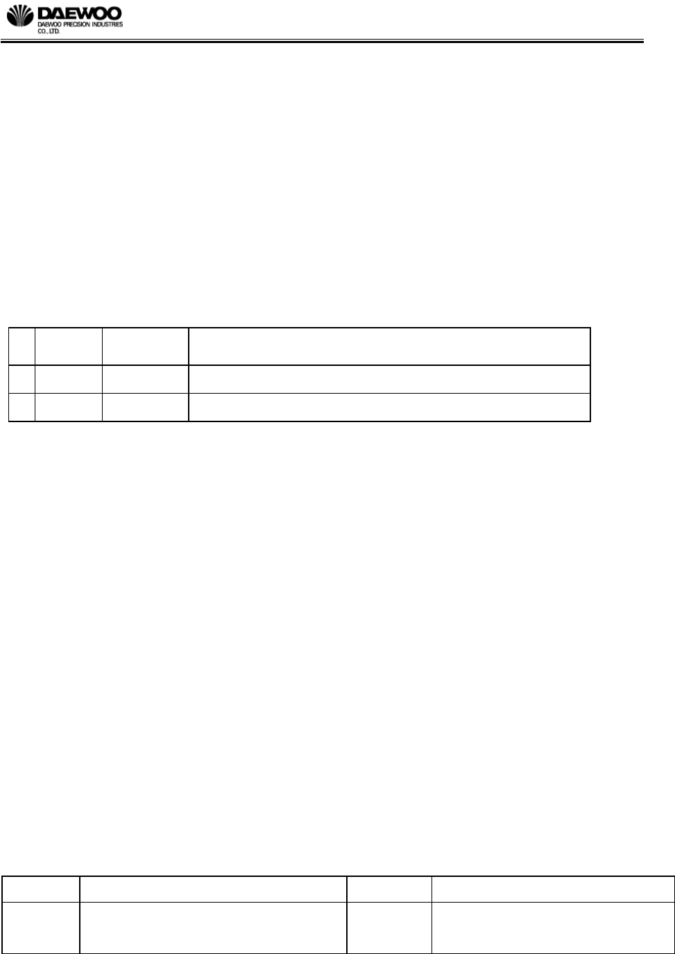
When the ignition is off, the key reminder is off and all doors(door / hood / trunk) are closed,
door lock by the Tx lock button. The Rx status goes to the arming mode in the condition of the
arming mode. For the information of the remote door lock, the hazard lamp blinks once for
0.5sec and the siren operates once 0.05sec.
When remote door lock is operated and not in the condition of the arming mode, hazard lamp
does not blink and Siren does not operation because of not changing Rx status.
When the ignition is off and the key reminder is off, the Rx drives the door actuator in order to
unlock all doors by the Tx unlock button. The Rx status goes to the disarming mode. For the
information of the remote door unlock, the hazard lamp blinks twice, the period is 1sec and the
duty ratio is 0.5sec. But if there was the burglar alarm, the hazard lamp blinking period is 2s
(0.5sec On and 1.5sec Off).

R&D / Automotive Electronics
Title Remote Keyless Entry System Specification Spec. No. DPE-AE-RK019912S
Written by Ban Dong Hoon Rev. No. A0
Date 10th . Nov. 2003 Page 8 / 25
3.1.2 TRANSMITTER DOOR / TRUNK
This system function by using two buttons of the valid Tx is shown at Table 2. Now we define
the “VALID Tx” as the ID code (Fixed code + Crypto code) of the Tx is memorized by the
Control Unit.
Status Button Function
A set / unset "DOOR" all door lock or unlock
according to lock_monitoring status
B set / unset "TRUNK" operating trunk solenoid and
chirp operating(0.05sec on / 0.45sec off)
[Table 2. System Function by Using Two Buttons of the Valid Tx]
When the ignition is off, the key reminder is off, all doors (door / hood / trunk) are closed and the
lock_monitoring signal is GND, door lock by the Tx door button. The Rx status goes to the
arming mode in the condition of the arming mode. For the information of the remote door lock,
the hazard lamp blinks once for 0.5sec and the siren operates once 0.05sec.
When remote door lock is operated and not in the condition of the arming mode, hazard lamp
does not blink and Siren does not operation because of not changing Rx status.
When the ignition is off, the key reminder is off and the lock_monitoring signal is open, the Rx
drives the door actuator in order to unlock all doors by the Tx door button. The Rx status goes to
the disarming mode. For the information of the remote door unlock, the hazard lamp blinks twice,
the period is 1sec and the duty ratio is 0.5sec. But if there was the burglar alarm, the hazard lamp
blinking period is 2s (0.5sec On and 1.5sec Off).
When the trunk function by the Tx trunk button operates, trunk solenoid is actuated for 500ms.
For the information of the remote trunk open, the siren operates twice, the period is 0.5sec
(0.05sec on 0.45sec off). But it does not change the Rx status.
R&D / Automotive Electronics
Title Remote Keyless Entry System Specification Spec. No. DPE-AE-RK019912S
Written by Ban Dong Hoon Rev. No. A0
Date 10th . Nov. 2003 Page 9 / 25
[Figure 2. FUNCTION FLOW]
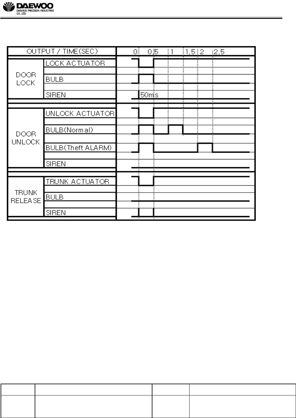
3.2 BURGLAR ALARM
At the arming mode, if below signal input is recognized by the Rx, the burglar alarm (audible
alarm (siren) and visible alarm(hazard Lamp) ) is activated 8 times during 28 seconds operated
and 5 seconds paused. The alarm activating count is the option by customer.
① When the door open switch input is turned to low(GND) (at the moment of opening the door)
② When the hood open switch input is turned to low(OPEN) (at the moment of opening the
hood)
③ When the trunk open switch input is turned to low(GND) (at the moment of opening the
trunk)
④ When the ignition switch input is turned to high(BAT) (at the moment of IGN on)
R&D / Automotive Electronics
Title Remote Keyless Entry System Specification Spec. No. DPE-AE-RK019912S
Written by Ban Dong Hoon Rev. No. A0
Date 10th . Nov. 2003 Page 10 / 25
If the above theft detection input is received at the arming mode, the type of theft is memorized at
the Rx EEPROM. But the alarm duration is not prolonged even if theft detection signal is
recognized during the alarm mode. That is, the Rx ignores the theft detection input until the
alarm is finished.
During the alarm is activated, if the “lock” , “unlock”, “door” function code is received, the Rx
performs the function according to be received code and the burglar alarm (audible alarm and
visible alarm) is deactivated. If the “trunk” function code is received, the Rx does not perform the
function and the burglar alarm is deactivated. And if the tamper switch (passenger unlock
disarming / driver unlock disarming / trunk unlock disarming) is ON, the Rx stops the burglar
alarm and goes to the disarming mode.
TIME sec
OUTPUT 0 0.25 0.5 0.75 27 27.25 27.5 27.75 28
SIREN
HAZARD
LAMP
[Figure 3. Timing Chart for Burglar Alarm]
3.3 DISARMING BY KEY CYLINDER
If the tamper switch (passenger unlock disarming / driver unlock disarming / trunk unlock
disarming) is ON, the Rx stops the burglar alarm and goes to the disarming mode.
R&D / Automotive Electronics
Title Remote Keyless Entry System Specification Spec. No. DPE-AE-RK019912S
Written by Ban Dong Hoon Rev. No. A0
Date 10th . Nov. 2003 Page 11 / 25
3.4 SAFETY LOCK(AUTO DOOR LOCK AFTER 30SEC)
At the arming mode, if the door / trunk / hood open and the ignition on is not occurred during 30
seconds after all door is unlocked by the Tx unlock button or the Tx door button, then all door is
locked again and the Rx also goes to the arming mode. At the case of the safety lock, even
though the Rx goes to the arming mode, the EEPROM data of the Rx about alarm is not changed.
If the remote door unlock is actuated again during the waiting time (30 seconds), the safety lock
process is restarted.
3.5 SECURITY INDICATOR
If the Rx status enters to the arming mode, the security indicator is blinking period 1sec (0.12sec
ON 0.88sec OFF).
Security Indicator RKE & ATAS Status
Blinking(f=1Hz) Duty cycle 1:7(ON/OFF) Arming, Trunk Rearming State
OFF Disarming Status
[Table 3. Security Indicator Operating timing Chart]
3.6 DIAGNOSTIC
Communication between the ECU and the diagnostic tester takes place in accordance with
ISO9141-2, with line K only but without line L. Line K is a bidirectional data line used to convey
request messages from the diagnostic tester to the ECU and response messages from the ECU to
the diagnostic tester. Additional DIAGNOSTIC function refers to the document
SPECIFICATION #DPE-AE-RK509603S Keyless Entry System Diagnostic Specification.
3.7 ACTIVE RANGE
Active functions of the receiver shall be operable when the Tx is with in the specified range of
the vehicle, as follows:
FUNCTION RANGE
All functions ≥10m : Ignition OFF
≥ 6m : Ignition OB
[Table 4. Active Range]

R&D / Automotive Electronics
Title Remote Keyless Entry System Specification Spec. No. DPE-AE-RK019912S
Written by Ban Dong Hoon Rev. No. A0
Date 10th . Nov. 2003 Page 12 / 25
Active range requirements shall be met with the receiver mounted in the vehicle in its production
intent mounting location and orientation. Range requirements are specified for open, flat, paved
terrain, with fair weather (no rain or snow), temperatures between 0°C and 80°C, and fob height
between 0.5 and 1.5 meters above the ground surface. Range shall be measured from the center
of the vehicle, and is independent of fob orientation.
'remote function' and 'ignition ON' range shall be determined with the engine running, and all
applicable vehicle functions (radio, rear defog, alarm, etc) in operation.
R&D / Automotive Electronics
Title Remote Keyless Entry System Specification Spec. No. DPE-AE-RK019912S
Written by Ban Dong Hoon Rev. No. A0
Date 10th . Nov. 2003 Page 13 / 25
4. SYSTEM CONFIGRATION
4.1 RECEIVER
4.1.1 FUNCTION
The control unit is operating the section “3. RKE FUNCTION”
4.1.2 ELECTRIC SPEC
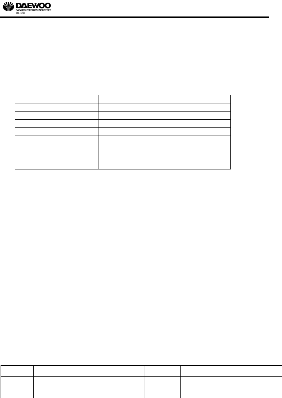
ITEM DISCRIPTION
operating voltage 8V ~ 16V(Test Voltage : 12.6V)
standby current MAX 5mA
sensitivity -100dbm(Min)
operating frequency 315(NA)/433.92(EU)MHz + 5KHz
operating temperature -40 ℃ ~ 85℃
Antenna type pole antenna
PCB thickness 16mm
PCB material FR - 4
[Table 5. Electric specification for Receiver]
4.1.3 METHOD OF CODING TRANSMITTER
The receiver is able to save 5EA transmitter security key (fixed code + hopping code)
Method for Tx coding (save the transmitter)
a. connect diagnostic connector and ALDL diagnostic device(SCAN-100 for GMDAT)
b. ALDL diagnostic device selects the coding mode
c. It is pressing the transmitter button 3 times.
d. confirm the message for coding ok of ALDL diagnostic device.
e. disconnect diagnostic connector and ALDL diagnostic device
R&D / Automotive Electronics
Title Remote Keyless Entry System Specification Spec. No. DPE-AE-RK019912S
Written by Ban Dong Hoon Rev. No. A0
Date 10th . Nov. 2003 Page 14 / 25
4.2 TRANSMITTER
4.2.1 ELECTRIC SPEC
ITEM DISCRIPTION
operating voltage 2.5V ~ 3.2V
standby current MAX 1uA
operating current Typically 9mA , MAX 14mA
output power 2000uV/m
modulation FSK
operating frequency 315(NA)/433.92(EU)MHz + 3KHz
operating temperature -20℃ ~ +70℃
Antenna type PCB Pattern ANTENNA
PCB thickness 8mm
PCB material FR-4
[Table 6. Electric specification for Transmitter]
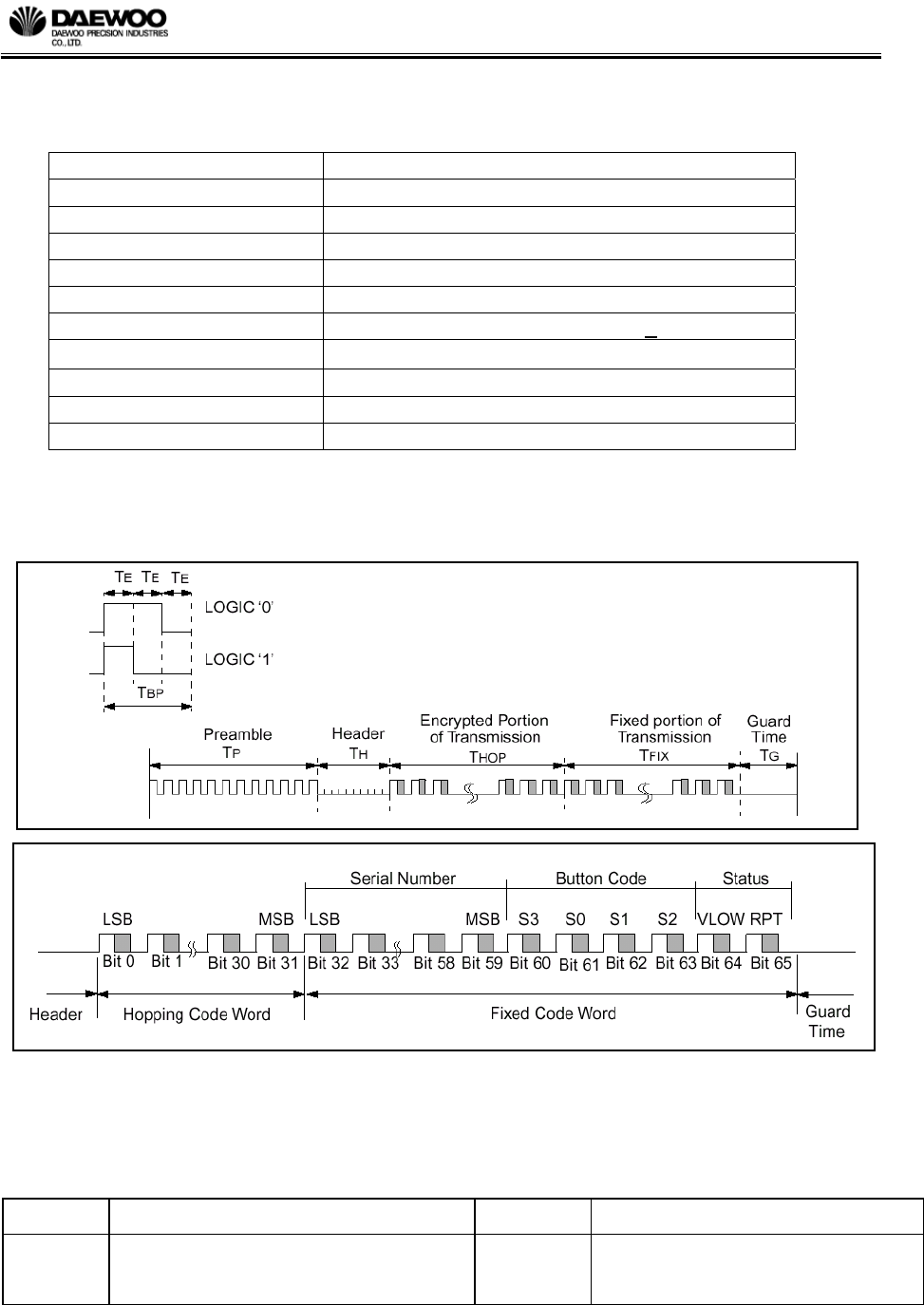
4.2.2 DATA FORMATION
[Figure 4. Data Code Formation]

R&D / Automotive Electronics
Title Remote Keyless Entry System Specification Spec. No. DPE-AE-RK019912S
Written by Ban Dong Hoon Rev. No. A0
Date 10th . Nov. 2003 Page 15 / 25
unit : us
ALL
Symbol Characteristic
Number
of TE Min. Typ. Max
TE Basic pulse element 1 260 400 660
TBP PQM bit pulse width 3 780 1200 1980
TP Preamble duration 23 6.0 9.2 15.2
TH Header duration 10 2.6 4.0 6.6
THOP Hopping Code duration 96 25.0 38.4 63.4
TFIX Fixed Code duration 102 26.5 40.8 67.3
TG Guard Time 39 10.1 15.6 25.7
Total Transmit Time 270 70.2 108.0 178.2
PWM data rate 1282 833 505
[Table 7. Data Bit Timing Table]
4.2.3 TRANSMITTER FUNCTION
The transmitter trans the high frequency signal using the PWM (Pulse Width Modulation)
method. The synchronization information, fixed information and switch information will be
encrypted to form the hopping code. The encrypted or hopping code portion of the transmission
will change every time a button is pressed, even if the same button is pushed again. Keeping a
button pressed for a long time will result in the same code word being transmitted until the button
is released or time-out occurs. If in the transmit process, it is detected that a new button is
pressed, the current code word will be aborted. A new code word will be transmitted and the
time-out counter will reset. If all the buttons are released, the minimum code words will be
completed.
4.2.4 BATTERY
Battery removal shall be able to be performed without specialized tools. Average time to replace
a battery shall be less than 5 minutes. No damage to the transmitter shall result if the batteries

R&D / Automotive Electronics
Title Remote Keyless Entry System Specification Spec. No. DPE-AE-RK019912S
Written by Ban Dong Hoon Rev. No. A0
Date 10th . Nov. 2003 Page 16 / 25
are installed backwards. Battery replacement shall not require the customer to handle any loose
components (i.e. circuit boards, battery clips, etc.).
Battery life shall exceed 2 years at 25°C based on usage specified in section 3.1.1, with
transmission time corresponding to 1 second duration button press activations.
4.2.5 LED
During the normal transmission the led operating is ON. If the supply voltage drops below the
low voltage trip point, the led is toggled at approximately 5Hz during the transmission.

R&D / Automotive Electronics
Title Remote Keyless Entry System Specification Spec. No. DPE-AE-RK019912S
Written by Ban Dong Hoon Rev. No. A0
Date 10th . Nov. 2003 Page 17 / 25
5. SYSTEM INPUT/OUTPUT CIRCUIT
5.1.1 SERIAL DATA LINK(NO. A17)
It is the line for communicate receiver and diagnostic device. It defines RKE diagnostic protocol
regulation(#DPE-AE-RK509603S)
5.1.2 ELECTRIC OUTPUT
5.1.2.1 HAZARD LAMP (LEFT : A26, RIGHT : A13)
- Type : Normal open Relay(V23072-C1061-A408)
- Output Level : Battery voltage to GND
- Max. switching current : 2 x 60 A
- Max. continuous current : 2 x 10 A @ +23℃
- Fault Diagnostic Request : No
- State During Reset : Off
- Short Circuit Protection Request : No
- Over Current Protection Request : No
- RIGHT LOAD : 21W x 2EA, 5W x 1EA
- LEFT LOAD : 21W x 2EA, 5W x 1EA
5.1.2.2 SECURITY INDICATOR(A19)
- Type : Low Side Drive
- Output Level : 1V to GND
- Max. Output Current : 100mA
- Min./Max. Duty Cycle : 0 / 100 %
- Fault Diagnostic Request : No
- State During Reset : Off
- Short Circuit Protection Request : No
- Over Current Protection Request : Yes
5.1.2.3 LOCK(A10)
- Type : Low Side Drive
- Max. Low Output Level : 1V to GND
- Max. Output Current : 500mA
- Fault Diagnostic Request : No
- State During Reset : Off
- Short Circuit Protection Request : Yes
- Over Current Protection Request : Yes
5.1.2.4 UNLOCK(A11)
- Type : Low Side Drive

R&D / Automotive Electronics
Title Remote Keyless Entry System Specification Spec. No. DPE-AE-RK019912S
Written by Ban Dong Hoon Rev. No. A0
Date 10th . Nov. 2003 Page 18 / 25
- Max. Low Output Level : 1V to GND
- Max. Output Current : 500mA
- Fault Diagnostic Request : No
- State During Reset : Off
- Short Circuit Protection Request : Yes
- Over Current Protection Request : Yes
5.1.2.5 2 STEP UNLOCK (A16, PROVISION)
- Type : Low Side Drive
- Max. Low Output Level : 1V to GND
- Max. Output Current : 500mA
- Fault Diagnostic Request : No
- State During Reset : Off
- Short Circuit Protection Request : Yes
- Over Current Protection Req’d : Yes
5.1.2.6 SIREN(A1)
- Type : Low Side Drive
- Max. Low Output Level : 1V to GND
- Max. Output Current : 500mA
- Fault Diagnostic Request : No
- State During Reset : Off
- Short Circuit Protection Request : No
- Over Current Protection Request : No
5.1.2.7 TRUNK RELEASE(A14)
- Type : Normal Open Relay
- Output Level : Battery Voltage to GND
- Max. Switching Current : 60 A
- Max. Continuous current : 10 A @ +23℃
- Fault Diagnostic Request : No
- State During Reset : Off
- Short Circuit Protection Request : No
- Over Current Protection Request : No
5.1.3 ELECTRIC INPUT

R&D / Automotive Electronics
Title Remote Keyless Entry System Specification Spec. No. DPE-AE-RK019912S
Written by Ban Dong Hoon Rev. No. A0
Date 10th . Nov. 2003 Page 19 / 25
5.1.3.1 TRUNK KEY CYLINDER UNLOCK SWITCH INPUT(A4)
■ Switch character
- Type : Normally Open Switch to Ground
- Function : Switch Closed – Unlock switch is ON
Switch Open – Unlock switch is OFF
- Open Resistance : >50kΩ
- Closed Resistance : <50Ω
- Open to Close Time : ≤5msec
- Close to Open Time : ≤5msec
- Noise & GND Offset Margin : ±1V
5.1.3.2 DDRIVER KEY CYLINDER LOCK SWITCH INPUT(A6)
■ Switch character
- Type : Normally Open Switch to Ground
- Function : Switch Closed – Lock switch is ON
Switch Open – Lock switch is OFF
- Open Resistance : >50kΩ
- Closed Resistance : <50Ω
- Open to Close Time : ≤5msec
- Close to Open Time : ≤5msec
- Noise & GND Offset Margin : ±1V
5.1.3.3 PASSENGER KEY Cylinder UNLOCK SWITCH INPUT(A22)
■ Switch character
- Type : Normally Open Switch to Ground
- Function : Switch Closed – Unlock switch is ON
Switch Open – Unlock switch is OFF
- Open Resistance : >50kΩ
- Closed Resistance : <50Ω
- Open to Close Time : ≤5msec
- Close to Open Time : ≤5msec
- Noise & GND Offset Margin : ±1V
5.1.3.4 HOOD OPEN SWITCH INPUT(A7)

R&D / Automotive Electronics
Title Remote Keyless Entry System Specification Spec. No. DPE-AE-RK019912S
Written by Ban Dong Hoon Rev. No. A0
Date 10th . Nov. 2003 Page 20 / 25
■ Switch character
- Type : Normally Close Switch to Battery
- Function : Switch Closed – HOOD Open
Switch Open – HOOD Close
- Open Resistance : >2MKΩ
- Closed Resistance : <50Ω
- Open to Close Time : ≤ 5msec
- Close to Open Time : ≤ 5msec
- Noise & GND. Offset Margin : ±1V
5.1.3.5 TRUNK(TAIL_GATE) OPEN SWITCH INPUT(A5)
■ Switch character
- Type : Normally Open Switch to Ground
- Function : Switch Closed – TRUNK Open
Switch Open – TRUNK Close
- Open Resistance : >50KΩ
- Closed Resistance : <50Ω
- Open to Close Time : ≤ 5msec
- Close to Open Time : ≤ 5msec
- Noise & GND. Offset Margin : ±1V
5.1.3.6 DOOR OPEN SWITCH INPUT (A8)
■ Switch character
- Type : Normally Open Switch to Ground
- Function : Switch Closed – DOOR Open
Switch Open – DOOR Close
- Open Resistance : >50KΩ
- Closed Resistance : <50Ω
- Open to Close Time : ≤ 5msec
- Close to Open Time : ≤ 5msec
- Noise & GND. Offset Margin : ±1V

R&D / Automotive Electronics
Title Remote Keyless Entry System Specification Spec. No. DPE-AE-RK019912S
Written by Ban Dong Hoon Rev. No. A0
Date 10th . Nov. 2003 Page 21 / 25
5.1.3.7 IGNITION SWITCH INPUT (A15)
■ Switch character
- Type : Normally Open Switch to Battery
- Function : Switch Closed – IGNITION is ON
Switch Open – IGNITION is OFF
- Open Resistance : >2MΩ
- Closed Resistance : <50Ω
- Open to Close Time : ≤ 5msec
- Close to Open Time : ≤ 5msec
- Noise & GND. Offset Margin : ±1V
5.1.3.8 KEY REMINDER SWITCH INPUT (A18)
■ Switch Character
- Type : Normally Open Switch to Battery
- Function : Switch Closed – Key Reminder is ON
Switch Open – Key Reminder is OFF
- Open Resistance : >2MΩ
- Closed Resistance : <50Ω
- Open to Close Time : ≤ 5msec
- Close to Open Time : ≤ 5msec
- Noise & GND. Offset Margin : ±1V
5.1.3.9 DOOR LOCK MONITORING SWITCH INPUT (A9)
■ Switch character
- Type : Normally Open Switch to Ground
- Function : Switch Closed – Lock switch is ON
Switch Open – Lock switch is OFF
- Open Resistance : >50kΩ
- Closed Resistance : <50Ω
- Open to Close Time : ≤ 5msec
- Close to Open Time : ≤ 5msec
- Noise & GND Offset Margin : ±1V
R&D / Automotive Electronics
Title Remote Keyless Entry System Specification Spec. No. DPE-AE-RK019912S
Written by Ban Dong Hoon Rev. No. A0
Date 10th . Nov. 2003 Page 22 / 25
NON-UL
Black
Blue
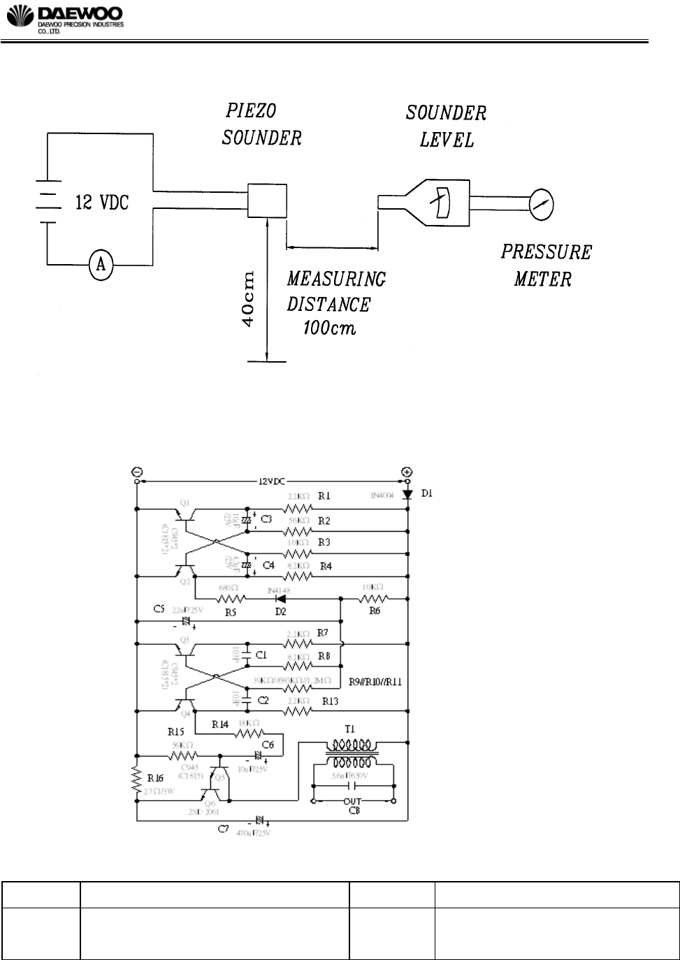
6. SIREN
6.1.1 ELECTRIC SPECIFICATION
No. Item Unit Specification Condition
1 Operating frequency range KHz 1.5 ~ 4.0
2 Operating Volt. range VDC 6 ~ 16
3 Current Consumption mA MAX 260 at 12VDC
4 Inrush current A MAX 2 at 12VDC
5 Sound pressure level dB MIN 105 at 1 m/12VDC
6 Tone Siren
7 Sweep Hz 2.7 ± 20% at 12VDC
8 Operating temp. ℃ -30 ~ +100
9 Storage temp. ℃ -40 ~ +110
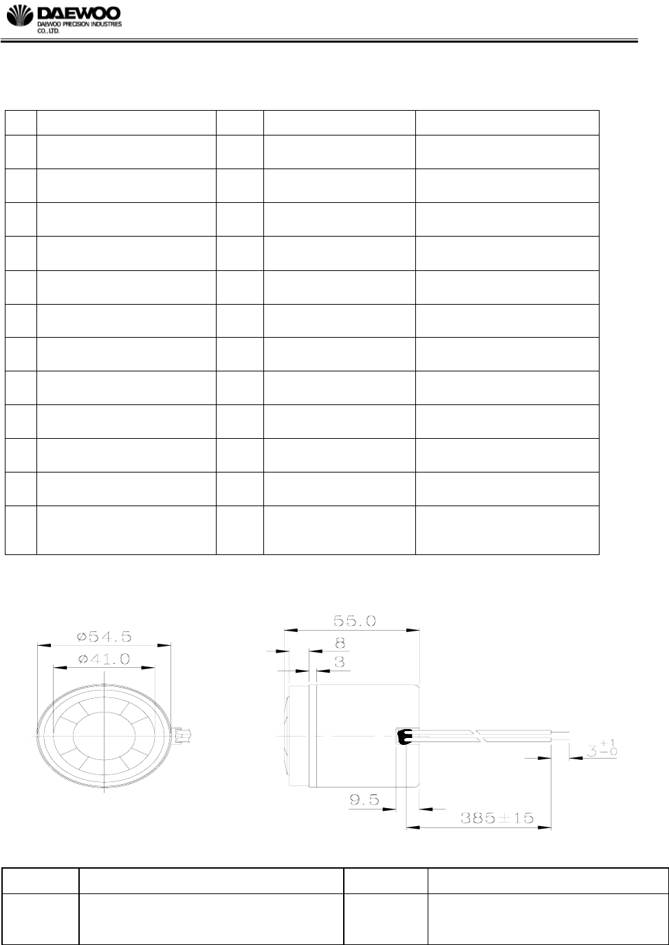
10 Dimension mm
φ54.5 x H55.0 see appearance drawing
11 Weight (MAX) gram 107.0
12 Material
ABS UL-94 1/16” HB
HIGH HEAT
(ALL BLACK)
6.1.2 APPEARANCE DRAWING
R&D / Automotive Electronics
Title Remote Keyless Entry System Specification Spec. No. DPE-AE-RK019912S
Written by Ban Dong Hoon Rev. No. A0
Date 10th . Nov. 2003 Page 23 / 25
6.1.3 MEASURING METHOD
6.1.4 Internal Oscillating Circuit
R&D / Automotive Electronics
Title Remote Keyless Entry System Specification Spec. No. DPE-AE-RK019912S
Written by Ban Dong Hoon Rev. No. A0
Date 10th . Nov. 2003 Page 24 / 25
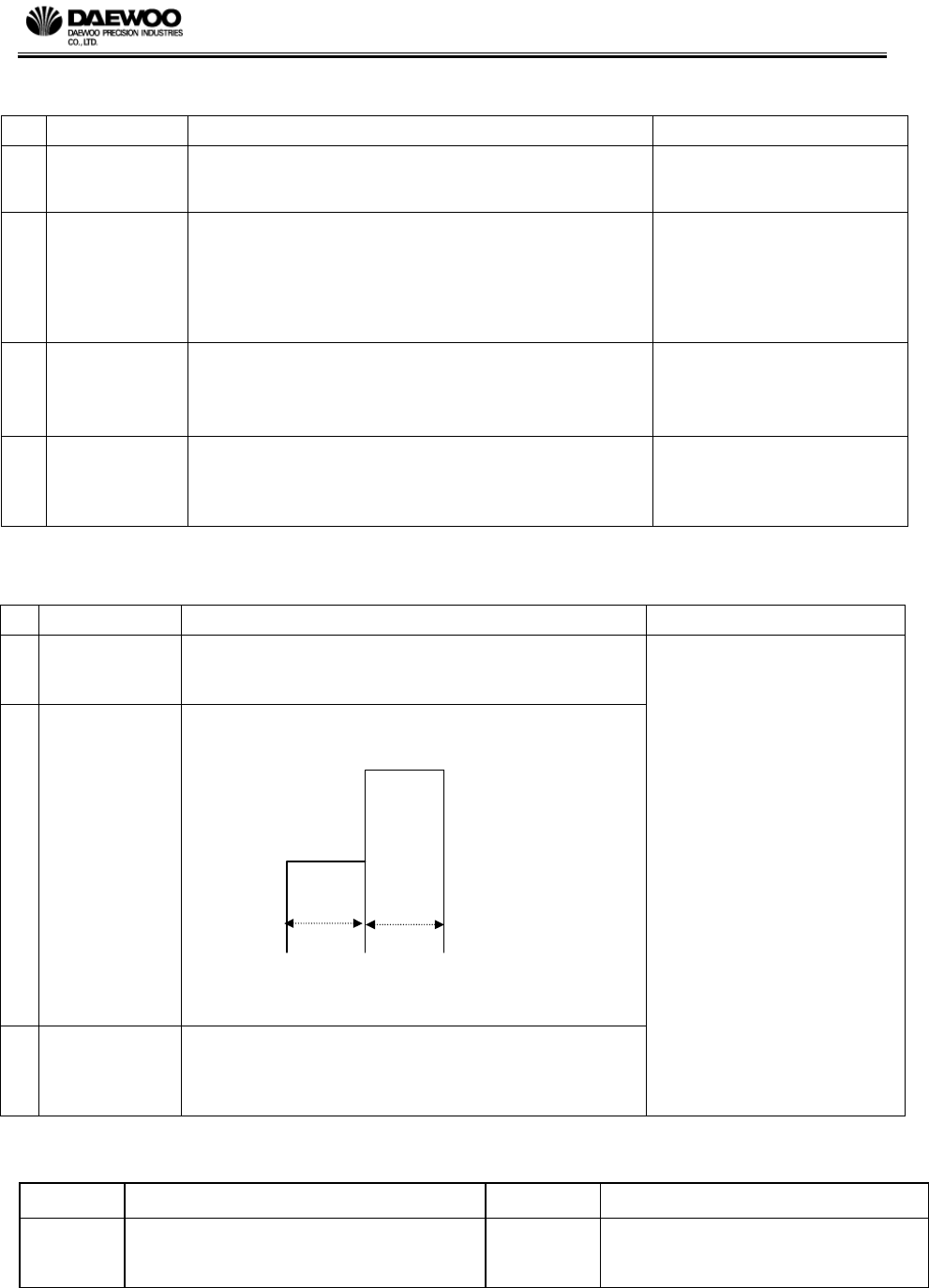
6.1.5 MECHANICAL CHARACTERISTICS
6.1.6 Environment Test
No. Item Test Condition Evaluation standard
1 frost
Placed at -40 ℃ for 8 hours and removed to at
+38 ℃,95%RH.Device testing will be done when an
uniform frost coating is observed on the device
2 thermal shock
The part shall be subjected to 5 thermal cycles. One
cycle shall be consisted of :
+110℃
-40℃
1 hr 1hr
Using 2 shuttle chambers with a 2 minutes minimum
transition.
3 storage
The part shall be subjected the uninterrupted storage
schedule as below;
-40℃:70hours
+110℃:118hours
Being placed for 2 hours at
+25℃, buzzer shall be
measured. The value of
current consumption should be
in ±20% compared with initial
ones .The SPL(min.):100dB.
The tone should be normal
No. Item Test Condition Evaluation standard
1 solder ability
Stripped wires of lead wires are immersed in rosin for 5
seconds and then immersed in solder bath of +230±5℃
for 3±0.5 seconds.
90% min. stripped wires shall
be wet with solder.(except the
edge of terminal)
2 soldering heat
resistance
Stripped wires are immersed up to 1.5mm from
insulation in solder bath of +300±5℃ for 3±0.5 seconds
or +260±5℃ for 10±1 seconds, and then sounder shall
be measured after being placed in natural condition for 4
hours.
no interference in operation
3 lead wire pull
strength
The pull force shall be applied to lead wire
: horizontal 3.0N
vertical 2.0N
no damage and cutting off.
4 vibration
The test shall last 4 hours and be performed in 3 primary
axis with a RMS G level=3.2G from 10 to 2000Hz..
operation shall be checked at
the end of each axis test.
Maintain the tolerance of ±4dB
R&D / Automotive Electronics
Title Remote Keyless Entry System Specification Spec. No. DPE-AE-RK019912S
Written by Ban Dong Hoon Rev. No. A0
Date 10th . Nov. 2003 Page 25 / 25
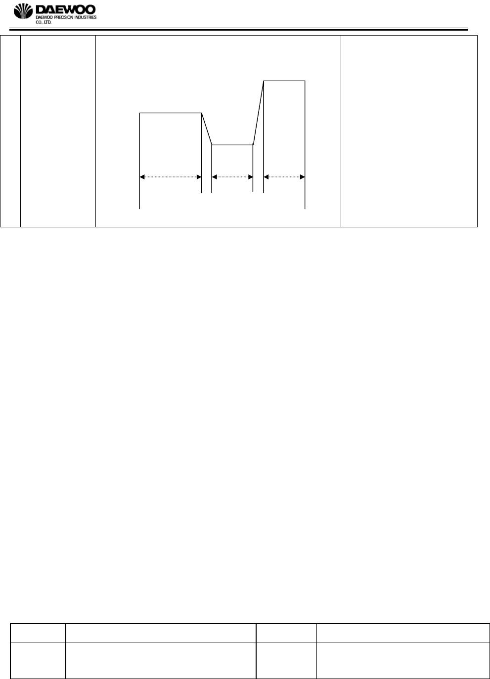
4
temperature.
and humidity
cycle test
The part shall be subjected to 5 cycles. One cycle shall
be consisted of::
+100℃
+37℃,98%RH
-40℃
12hrs 6hrs 6hrs
Perform a functional check of each unit every 12 hours