Daewoo Precision RK950NAT Remote Keyless Entry System (Transmitter) User Manual DPI Instruction Manual
Daewoo Precision Industries Ltd Remote Keyless Entry System (Transmitter) DPI Instruction Manual
UserManual.wiki
>
Daewoo Precision
>
RK950NAT User Manual
Users Manual
Navigation menu
Upload a User Manual
Namespaces
Wiki Guide
HTML
PDF
Info
Views
User Manual
Discussion / Help
Navigation
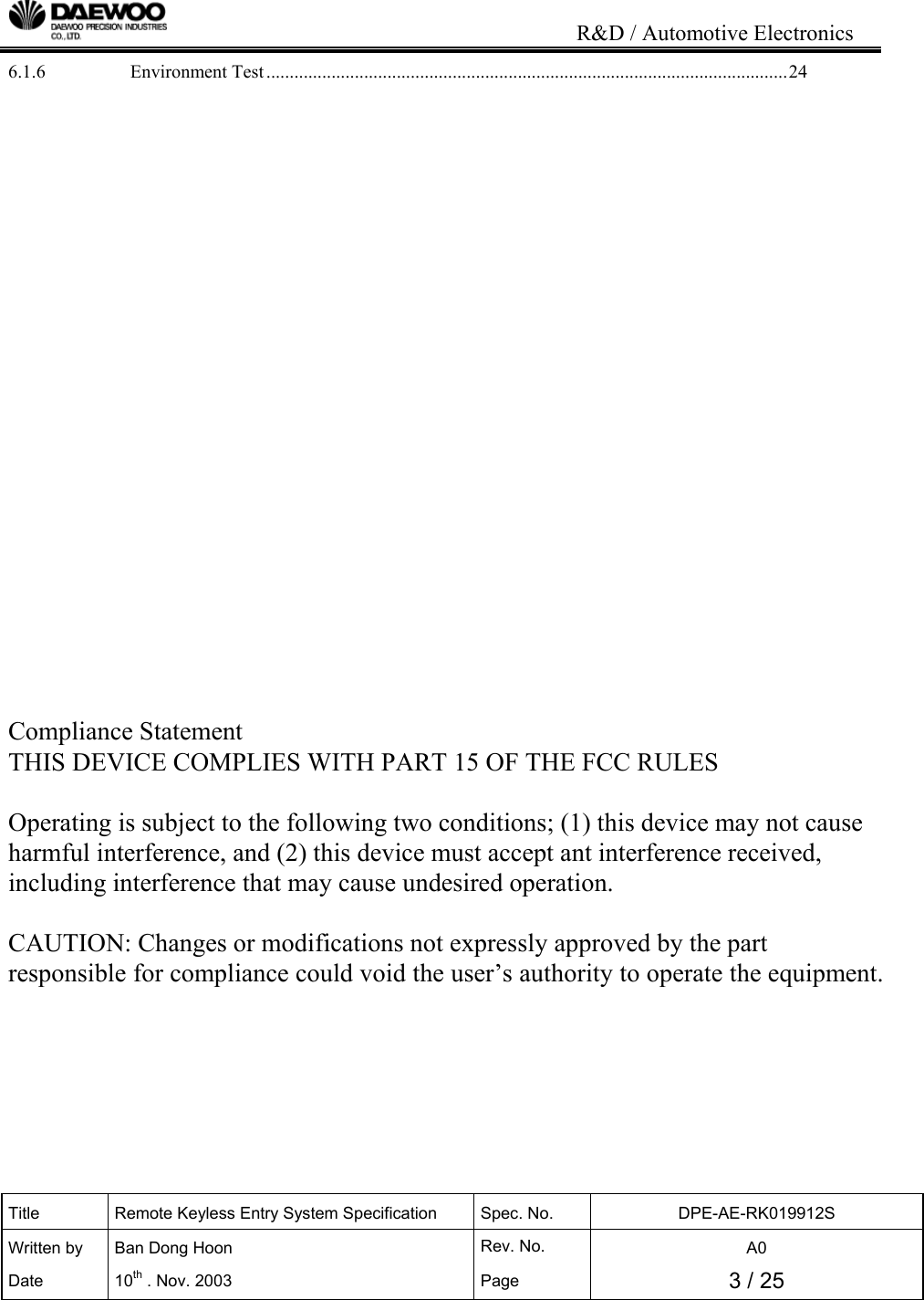
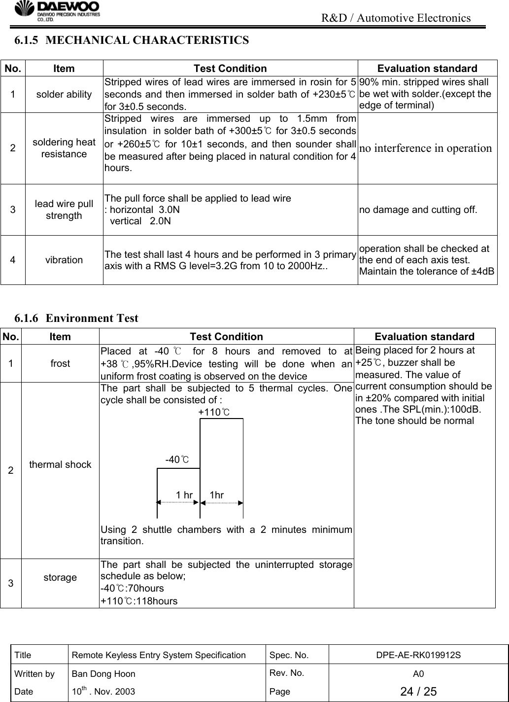
![R&D / Automotive Electronics Title Remote Keyless Entry System Specification Spec. No. DPE-AE-RK019912S Written by Ban Dong Hoon Rev. No. A0 Date 10th . Nov. 2003 Page 6 / 25 [Figure 1. SYSTEM BLOCK DIAGRAM] A12A18³»Àå TRUNK LID OPEN SW TRUNK UNLOCKA26KEY INSERTA5 RIGHT FLASHING BULBCOMMUNICATION LINE ( P )UNLOCKDOORLOCKRELAYB+B+DRIVERDOOR LA TCH SWRR RF ANTENNA15A A8LOCKSIRENA20 A1A4DOOR LOCK CHECKA16A11 RLSECURITY INDICATORCODING EQUIPMENT(OBD #8) RR TRUNK KEY CYLINDER UNLOCK SWDRIVER UNLOCK DISARMINGDOOR OPENA9A25A2,A3A14 TRUNK OPEN SWTRUNK OPENA22A17KEY REMIND SWLEFT FLASHING BULB FRKEY LOCK ARMING ( P )TRUNK OPEN SOLENOID IGNDRIV ERA13CTRL LOCK/UNLOCK SW FLA15A192-STEP UNLOCK ( P )A7HOOD OPENCONTROLSYSTEMCO-DRIVER UNLOCK DISARMINGCOMMUNICATION LINEDREAM NETB+ PASSENGER A6 B+KEY CYLINDER LOCK/UNLOCK SW PASSENGERGNDB+TRUNK RELEASE ( P ) IGN1RL A10 HOOD OPEN SW 30A](https://usermanual.wiki/Daewoo-Precision/RK950NAT/User-Guide-568563-Page-6.png)
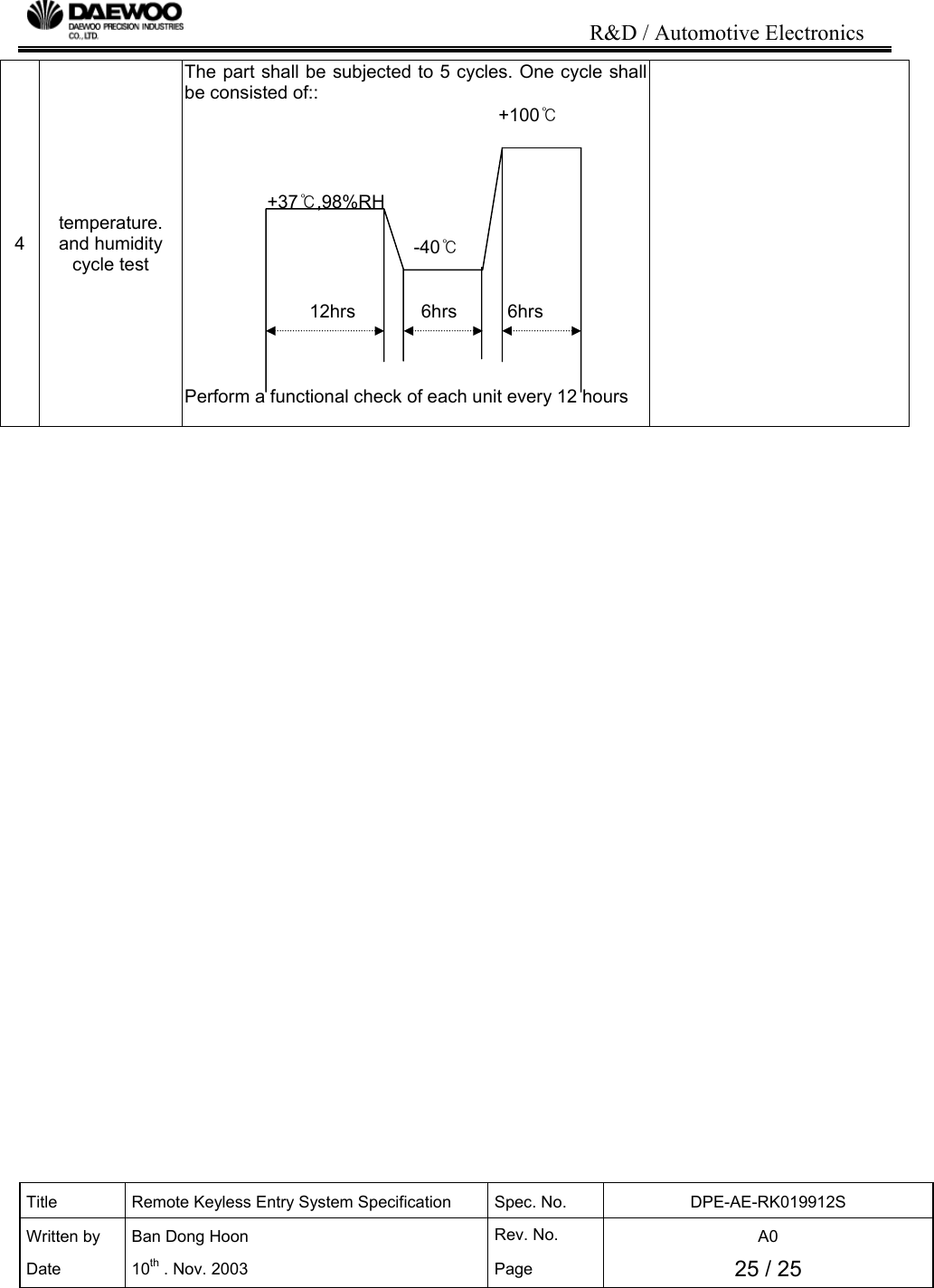
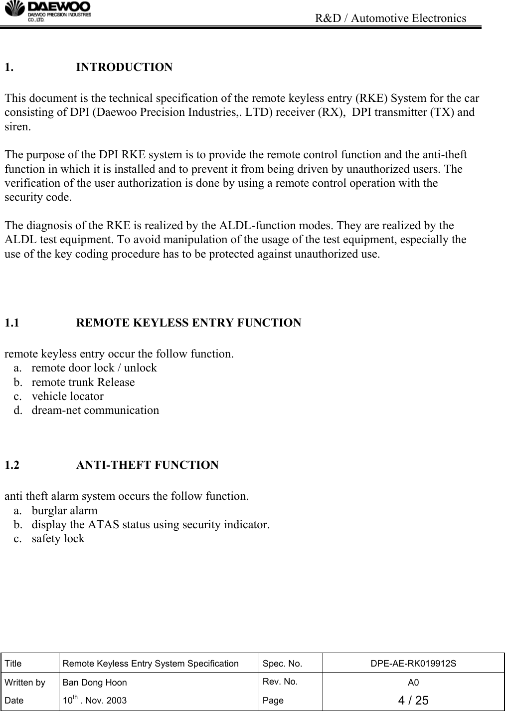
![R&D / Automotive Electronics Title Remote Keyless Entry System Specification Spec. No. DPE-AE-RK019912S Written by Ban Dong Hoon Rev. No. A0 Date 10th . Nov. 2003 Page 7 / 25 3. RKE FUNCTION 3.1 DOOR LOCK / UNLOCK USING TRANSMITTER 3.1.1 TRANSMITTER LOCK / UNLOCK This system function by using two buttons of the valid Tx is shown at Table 1. Now we define the “VALID Tx” as the ID code (Fixed code + Crypto code) of the Tx is memorized by the Control Unit. Status Button Function A Unset "UNLOCK" All door unlock, Hazard lamp blink twice, Disarming ModeB Set "LOCK" All door lock, Hazard lamp blink once, Arming Mode [Table 1. System Function by Using Two Buttons of the Valid Tx] When the ignition is off, the key reminder is off and all doors(door / hood / trunk) are closed, door lock by the Tx lock button. The Rx status goes to the arming mode in the condition of the arming mode. For the information of the remote door lock, the hazard lamp blinks once for 0.5sec and the siren operates once 0.05sec. When remote door lock is operated and not in the condition of the arming mode, hazard lamp does not blink and Siren does not operation because of not changing Rx status. When the ignition is off and the key reminder is off, the Rx drives the door actuator in order to unlock all doors by the Tx unlock button. The Rx status goes to the disarming mode. For the information of the remote door unlock, the hazard lamp blinks twice, the period is 1sec and the duty ratio is 0.5sec. But if there was the burglar alarm, the hazard lamp blinking period is 2s (0.5sec On and 1.5sec Off).](https://usermanual.wiki/Daewoo-Precision/RK950NAT/User-Guide-568563-Page-7.png)
![R&D / Automotive Electronics Title Remote Keyless Entry System Specification Spec. No. DPE-AE-RK019912S Written by Ban Dong Hoon Rev. No. A0 Date 10th . Nov. 2003 Page 8 / 25 3.1.2 TRANSMITTER DOOR / TRUNK This system function by using two buttons of the valid Tx is shown at Table 2. Now we define the “VALID Tx” as the ID code (Fixed code + Crypto code) of the Tx is memorized by the Control Unit. Status Button Function A set / unset "DOOR" all door lock or unlock according to lock_monitoring status B set / unset "TRUNK" operating trunk solenoid and chirp operating(0.05sec on / 0.45sec off) [Table 2. System Function by Using Two Buttons of the Valid Tx] When the ignition is off, the key reminder is off, all doors (door / hood / trunk) are closed and the lock_monitoring signal is GND, door lock by the Tx door button. The Rx status goes to the arming mode in the condition of the arming mode. For the information of the remote door lock, the hazard lamp blinks once for 0.5sec and the siren operates once 0.05sec. When remote door lock is operated and not in the condition of the arming mode, hazard lamp does not blink and Siren does not operation because of not changing Rx status. When the ignition is off, the key reminder is off and the lock_monitoring signal is open, the Rx drives the door actuator in order to unlock all doors by the Tx door button. The Rx status goes to the disarming mode. For the information of the remote door unlock, the hazard lamp blinks twice, the period is 1sec and the duty ratio is 0.5sec. But if there was the burglar alarm, the hazard lamp blinking period is 2s (0.5sec On and 1.5sec Off). When the trunk function by the Tx trunk button operates, trunk solenoid is actuated for 500ms. For the information of the remote trunk open, the siren operates twice, the period is 0.5sec (0.05sec on 0.45sec off). But it does not change the Rx status.](https://usermanual.wiki/Daewoo-Precision/RK950NAT/User-Guide-568563-Page-8.png)
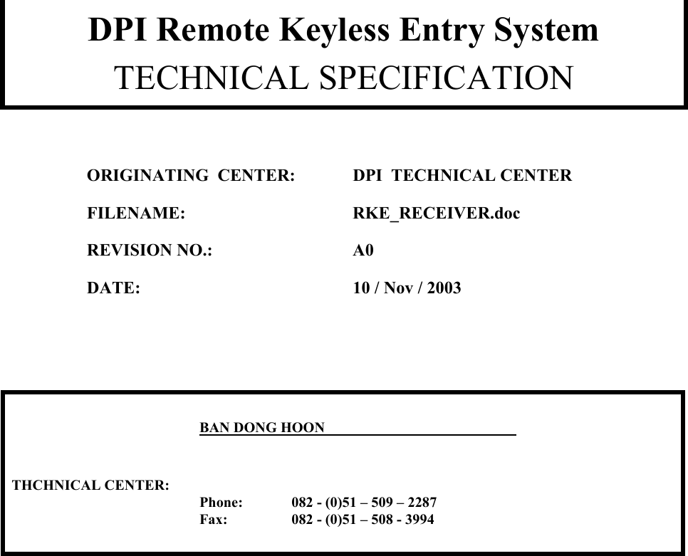
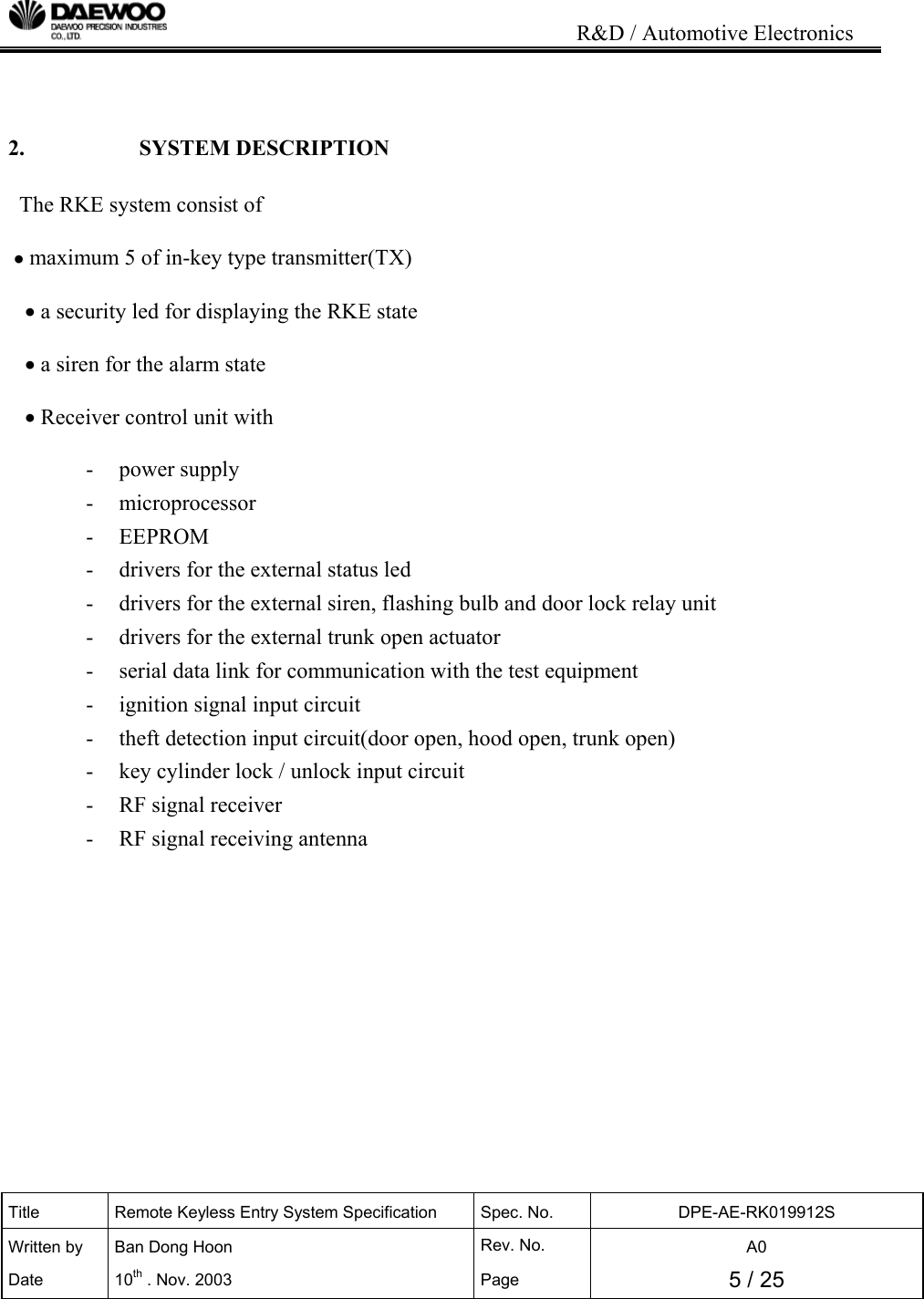
![R&D / Automotive Electronics Title Remote Keyless Entry System Specification Spec. No. DPE-AE-RK019912S Written by Ban Dong Hoon Rev. No. A0 Date 10th . Nov. 2003 Page 9 / 25 [Figure 2. FUNCTION FLOW] 3.2 BURGLAR ALARM At the arming mode, if below signal input is recognized by the Rx, the burglar alarm (audible alarm (siren) and visible alarm(hazard Lamp) ) is activated 8 times during 28 seconds operated and 5 seconds paused. The alarm activating count is the option by customer. ① When the door open switch input is turned to low(GND) (at the moment of opening the door) ② When the hood open switch input is turned to low(OPEN) (at the moment of opening the hood) ③ When the trunk open switch input is turned to low(GND) (at the moment of opening the trunk) ④ When the ignition switch input is turned to high(BAT) (at the moment of IGN on)](https://usermanual.wiki/Daewoo-Precision/RK950NAT/User-Guide-568563-Page-9.png)
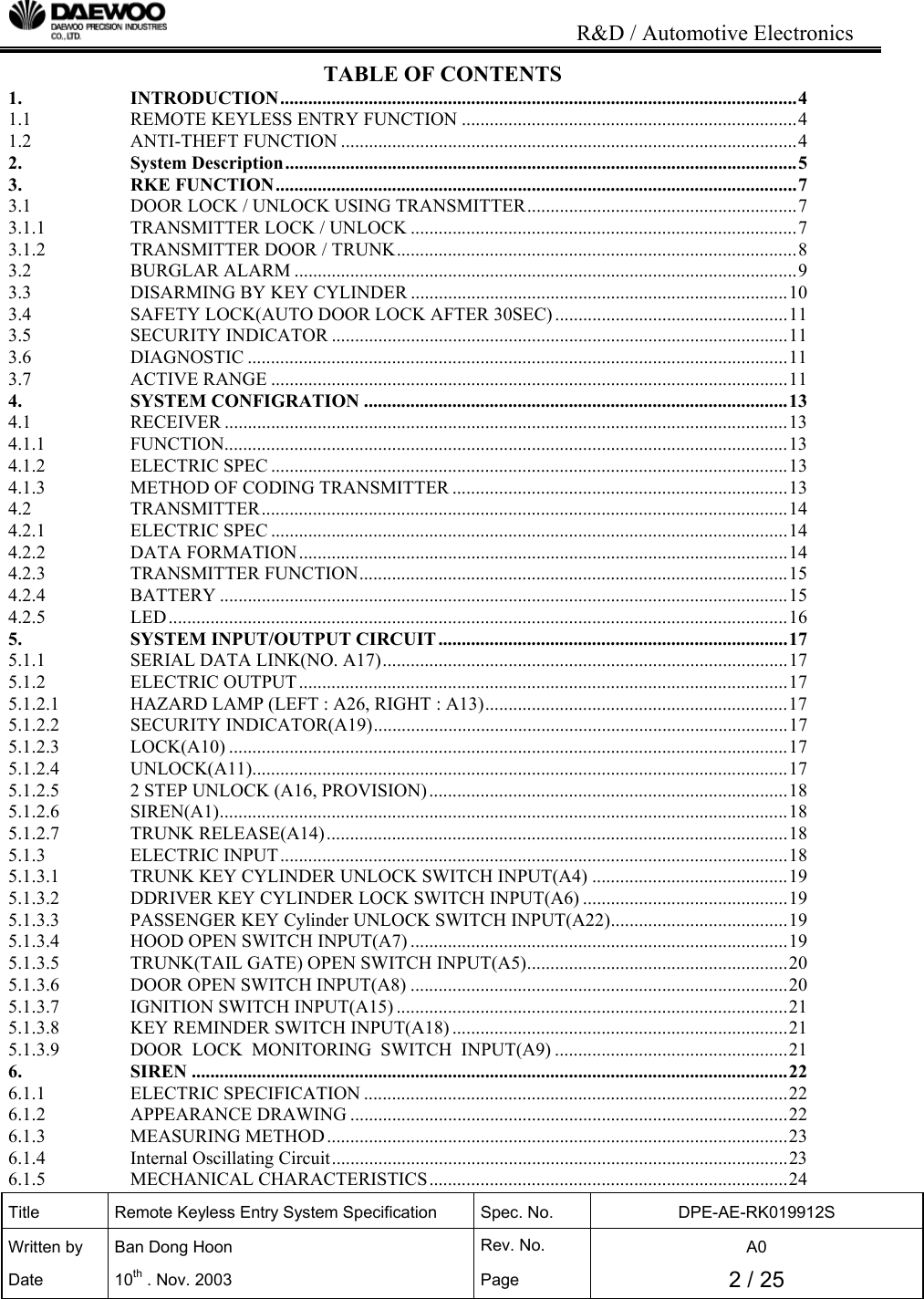
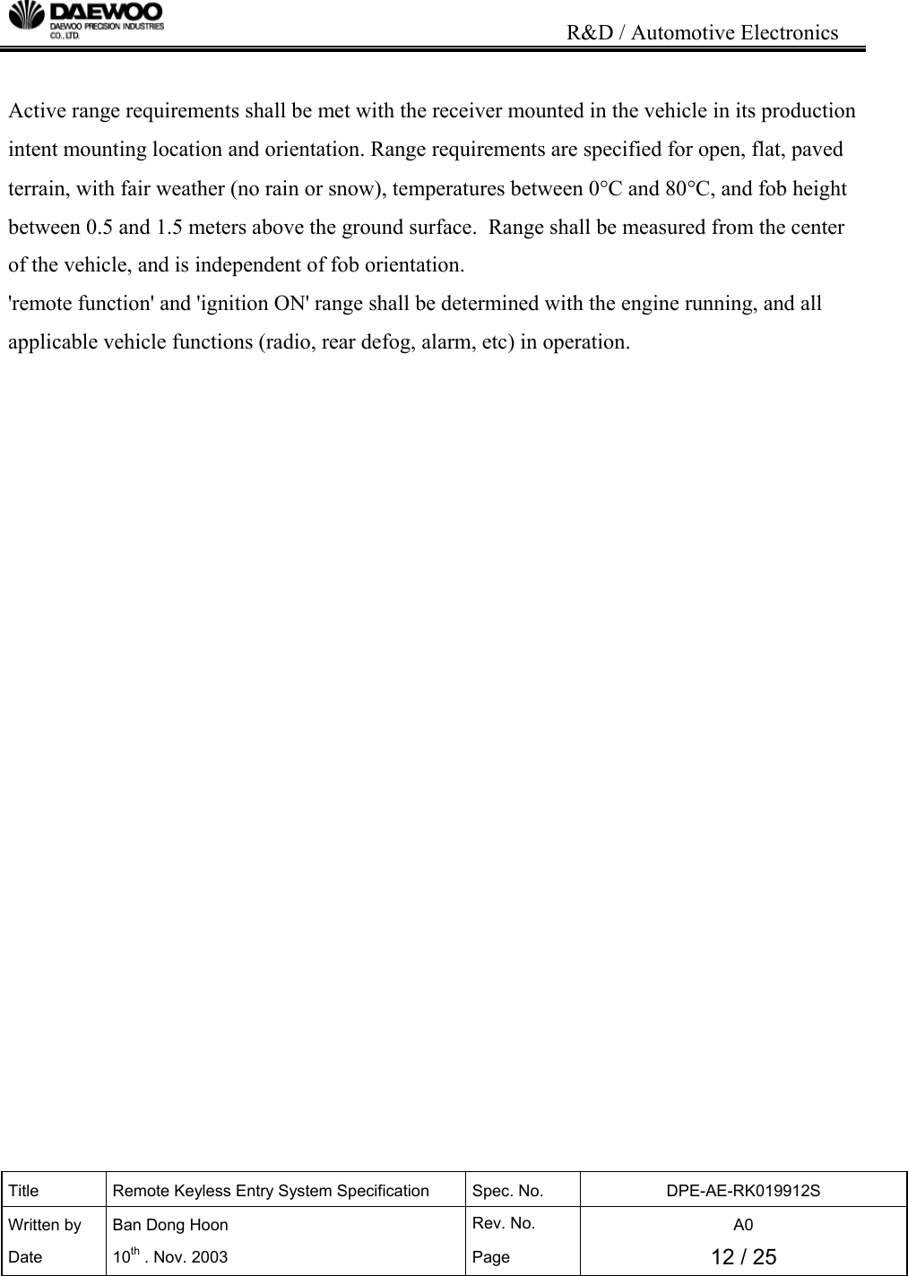
![R&D / Automotive Electronics Title Remote Keyless Entry System Specification Spec. No. DPE-AE-RK019912S Written by Ban Dong Hoon Rev. No. A0 Date 10th . Nov. 2003 Page 10 / 25 If the above theft detection input is received at the arming mode, the type of theft is memorized at the Rx EEPROM. But the alarm duration is not prolonged even if theft detection signal is recognized during the alarm mode. That is, the Rx ignores the theft detection input until the alarm is finished. During the alarm is activated, if the “lock” , “unlock”, “door” function code is received, the Rx performs the function according to be received code and the burglar alarm (audible alarm and visible alarm) is deactivated. If the “trunk” function code is received, the Rx does not perform the function and the burglar alarm is deactivated. And if the tamper switch (passenger unlock disarming / driver unlock disarming / trunk unlock disarming) is ON, the Rx stops the burglar alarm and goes to the disarming mode. TIME sec OUTPUT 0 0.25 0.5 0.75 27 27.25 27.5 27.75 28 SIREN HAZARD LAMP [Figure 3. Timing Chart for Burglar Alarm] 3.3 DISARMING BY KEY CYLINDER If the tamper switch (passenger unlock disarming / driver unlock disarming / trunk unlock disarming) is ON, the Rx stops the burglar alarm and goes to the disarming mode.](https://usermanual.wiki/Daewoo-Precision/RK950NAT/User-Guide-568563-Page-10.png)
![R&D / Automotive Electronics Title Remote Keyless Entry System Specification Spec. No. DPE-AE-RK019912S Written by Ban Dong Hoon Rev. No. A0 Date 10th . Nov. 2003 Page 11 / 25 3.4 SAFETY LOCK(AUTO DOOR LOCK AFTER 30SEC) At the arming mode, if the door / trunk / hood open and the ignition on is not occurred during 30 seconds after all door is unlocked by the Tx unlock button or the Tx door button, then all door is locked again and the Rx also goes to the arming mode. At the case of the safety lock, even though the Rx goes to the arming mode, the EEPROM data of the Rx about alarm is not changed. If the remote door unlock is actuated again during the waiting time (30 seconds), the safety lock process is restarted. 3.5 SECURITY INDICATOR If the Rx status enters to the arming mode, the security indicator is blinking period 1sec (0.12sec ON 0.88sec OFF). Security Indicator RKE & ATAS Status Blinking(f=1Hz) Duty cycle 1:7(ON/OFF) Arming, Trunk Rearming State OFF Disarming Status [Table 3. Security Indicator Operating timing Chart] 3.6 DIAGNOSTIC Communication between the ECU and the diagnostic tester takes place in accordance with ISO9141-2, with line K only but without line L. Line K is a bidirectional data line used to convey request messages from the diagnostic tester to the ECU and response messages from the ECU to the diagnostic tester. Additional DIAGNOSTIC function refers to the document SPECIFICATION #DPE-AE-RK509603S Keyless Entry System Diagnostic Specification. 3.7 ACTIVE RANGE Active functions of the receiver shall be operable when the Tx is with in the specified range of the vehicle, as follows: FUNCTION RANGE All functions ≥10m : Ignition OFF ≥ 6m : Ignition OB [Table 4. Active Range]](https://usermanual.wiki/Daewoo-Precision/RK950NAT/User-Guide-568563-Page-11.png)
![R&D / Automotive Electronics Title Remote Keyless Entry System Specification Spec. No. DPE-AE-RK019912S Written by Ban Dong Hoon Rev. No. A0 Date 10th . Nov. 2003 Page 13 / 25 4. SYSTEM CONFIGRATION 4.1 RECEIVER 4.1.1 FUNCTION The control unit is operating the section “3. RKE FUNCTION” 4.1.2 ELECTRIC SPEC ITEM DISCRIPTION operating voltage 8V ~ 16V(Test Voltage : 12.6V) standby current MAX 5mA sensitivity -100dbm(Min) operating frequency 315(NA)/433.92(EU)MHz + 5KHz operating temperature -40 ℃ ~ 85℃ Antenna type pole antenna PCB thickness 16mm PCB material FR - 4 [Table 5. Electric specification for Receiver] 4.1.3 METHOD OF CODING TRANSMITTER The receiver is able to save 5EA transmitter security key (fixed code + hopping code) Method for Tx coding (save the transmitter) a. connect diagnostic connector and ALDL diagnostic device(SCAN-100 for GMDAT) b. ALDL diagnostic device selects the coding mode c. It is pressing the transmitter button 3 times. d. confirm the message for coding ok of ALDL diagnostic device. e. disconnect diagnostic connector and ALDL diagnostic device](https://usermanual.wiki/Daewoo-Precision/RK950NAT/User-Guide-568563-Page-13.png)
![R&D / Automotive Electronics Title Remote Keyless Entry System Specification Spec. No. DPE-AE-RK019912S Written by Ban Dong Hoon Rev. No. A0 Date 10th . Nov. 2003 Page 14 / 25 4.2 TRANSMITTER 4.2.1 ELECTRIC SPEC ITEM DISCRIPTION operating voltage 2.5V ~ 3.2V standby current MAX 1uA operating current Typically 9mA , MAX 14mA output power 2000uV/m modulation FSK operating frequency 315(NA)/433.92(EU)MHz + 3KHz operating temperature -20℃ ~ +70℃ Antenna type PCB Pattern ANTENNA PCB thickness 8mm PCB material FR-4 [Table 6. Electric specification for Transmitter] 4.2.2 DATA FORMATION [Figure 4. Data Code Formation]](https://usermanual.wiki/Daewoo-Precision/RK950NAT/User-Guide-568563-Page-14.png)
![R&D / Automotive Electronics Title Remote Keyless Entry System Specification Spec. No. DPE-AE-RK019912S Written by Ban Dong Hoon Rev. No. A0 Date 10th . Nov. 2003 Page 15 / 25 unit : us ALL Symbol Characteristic Number of TE Min. Typ. Max TE Basic pulse element 1 260 400 660 TBP PQM bit pulse width 3 780 1200 1980 TP Preamble duration 23 6.0 9.2 15.2 TH Header duration 10 2.6 4.0 6.6 THOP Hopping Code duration 96 25.0 38.4 63.4 TFIX Fixed Code duration 102 26.5 40.8 67.3 TG Guard Time 39 10.1 15.6 25.7 Total Transmit Time 270 70.2 108.0 178.2 PWM data rate 1282 833 505 [Table 7. Data Bit Timing Table] 4.2.3 TRANSMITTER FUNCTION The transmitter trans the high frequency signal using the PWM (Pulse Width Modulation) method. The synchronization information, fixed information and switch information will be encrypted to form the hopping code. The encrypted or hopping code portion of the transmission will change every time a button is pressed, even if the same button is pushed again. Keeping a button pressed for a long time will result in the same code word being transmitted until the button is released or time-out occurs. If in the transmit process, it is detected that a new button is pressed, the current code word will be aborted. A new code word will be transmitted and the time-out counter will reset. If all the buttons are released, the minimum code words will be completed. 4.2.4 BATTERY Battery removal shall be able to be performed without specialized tools. Average time to replace a battery shall be less than 5 minutes. No damage to the transmitter shall result if the batteries](https://usermanual.wiki/Daewoo-Precision/RK950NAT/User-Guide-568563-Page-15.png)