Dakota Alert Inc Home Security System Bbt 2500 Users Manual
Break Beam Alert BBA-2500 BBT-2500
BBT-2500 to the manual ad20abd6-ce5c-48ae-ba1d-758faf0a2a42
2015-02-04
: Dakota-Alert Dakota-Alert-Dakota-Alert-Inc-Home-Security-System-Bbt-2500-Users-Manual-511034 dakota-alert-dakota-alert-inc-home-security-system-bbt-2500-users-manual-511034 dakota-alert pdf
Open the PDF directly: View PDF ![]() .
.
Page Count: 8
BBT-2500
Break Beam Transmitter
User Guide
www.dakotaalert.com
PRODUCT DESCRIPTION: The BBT-2500 is used with the DCR-2500 receiver. The BBT-2500
uses Active Infrared to detect anything that passes through the sensor pair and breaks both
beams at the same time. When the beams are broken, the unit sends a signal to the receiver.
This will sound one of four dierent tones (Classical, Westminster Chime, Ding Dong, or
Whistle). The BBT-2500 can be used to monitor access into any area, from your backyard to
lumber yard and everything in between.
READ MANUAL THOROUGHLY BEFORE INSTALLATION. RETAIN MANUAL FOR FUTURE
REFERENCE. FAILURE TO FOLLOW DIRECTIONS PROPERLY MAY RESULT IN DAMAGE.
ONLY use this product for the detection of moving objects such as people and vehicles.
DO NOT disassemble or attempt to repair the product.
DO NOT install this unit with any other infrared detector. It may cause false alarms.
DO clean and inspect the unit regularly for proper use. If any problem is found, contact
Dakota Alert, Inc.
WARNINGS: This device complies with Part 15 of the FCC rules, Operation of this device is
subject to the following conditions: 1. This device may not cause harmful interference. 2.
This device must accept any interference, including interference that may cause undesired
operation.
HARDWARE INSTALLATION
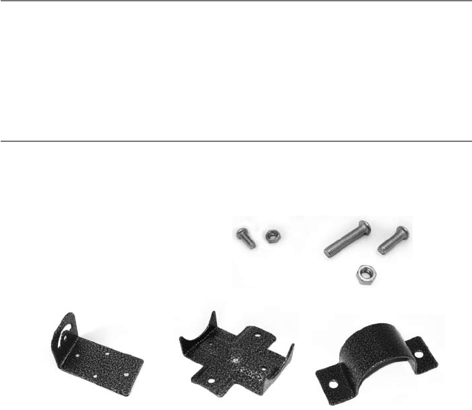
Verify that all installation hardware
is included. Tools needed: Phillips
screwdriver, adjustable wrench. (8) M4x12mm screws
(8) M4 nuts
(8) M5x27mm screws
(8) M5x18mm screws
(16) M5 nuts
(4) Cross Brackets(4) Right Angle Brackets (4) ‘U’ Shaped Brackets
2
3
PAIRING
To make installation easier
it is recommended to pair
units ‘A’ and ‘B’ before
mounting.
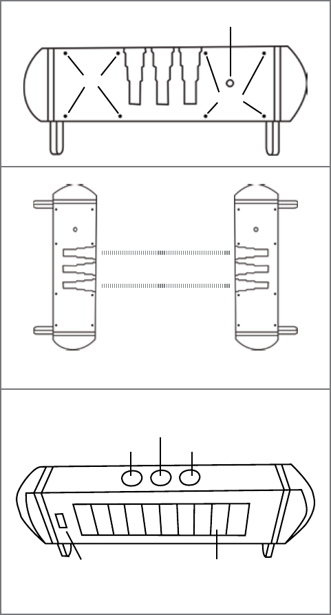
On a at surface push the
power button (Figure 1-1)
on ‘A’ then push the power
button on ‘B’. Laying the
units at on counter or
table, line up the infrared
light holes (Figure 1-2).
The units will then pair.
You will see lights ashing
during this process. Leave
the units in place for one
minute to make sure this
process is complete.
Once paired, test them by
completely blocking all
3 holes (2 infrared light
holes and indicator hole
shown in Figure 1-3).
Unit should send a signal
to the DCR-2500 and
sound an alert. Unit will
only alert if all 3 holes are
completely blocked for at
least 100ms. If an object
passes through the beam
faster than that it will not
be detected.
‘A’ unit contains the radio
transmitter module.
The ‘A’ unit transmitter
module is factory set to
match the zone 2 setting
of the DCR-2500. It is not
recommended to change
the code setting unless
it is needed to avoid
interference or a dierent
zone is desired. Be careful
when opening this unit to avoid damaging any internal components or wires.
‘B’ unit contains no user serviceable parts. It is not recommended to open this unit.
Figure 1-3
Infrared Light Hole Infrared Light Hole
Indicator Hole
Solar PanelLevel
Front of unit
Power Button
Screws
Screws
Back of unit
Figure 1-1
Figure 1-2
Place units 6 to 12 inches
apart for pairing
Below are the two most common mounting
options.
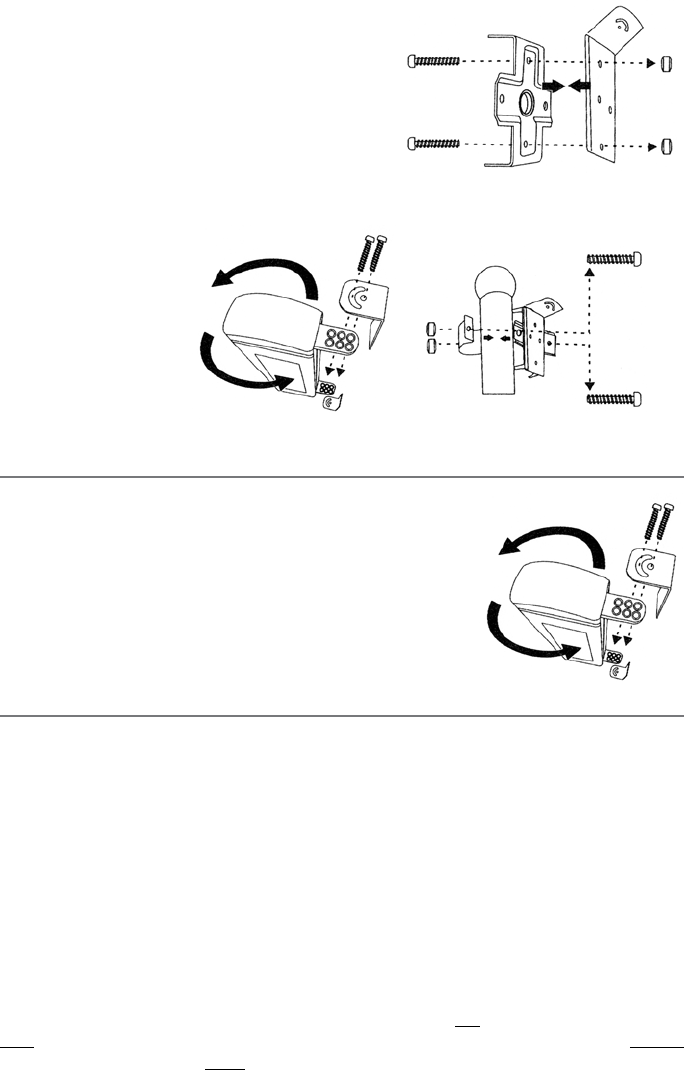
CIRCULAR POST MOUNTING
1). Take the right angle bracket (Figure 3-1) and
attach the cross bracket using (2) M4 nuts and (2)
M4x12mm screws. Repeat for all brackets.
2). Using (2) M5 nuts and (2) M5x18mm screws
attach right
angle bracket
(Figure 3-2) to
units ‘A’ and ‘B’.
3). Attach to post
with ‘U’ shaped
bracket (Figure
3-3) . Using (2)
M5 nuts and
(2) M5x27mm
screws attach ‘U’
bracket around post. Tighten securely.
FLAT SURFACE MOUNTING
1). Using (2) M5 nuts and (2) M5x18mm screws attach
right angle bracket (Figure 4) to units ‘A’ and ‘B’.
2). Use screws that are appropriate for your material
and surface (not included) and mount right angle
bracket taking care to keep units ‘A’ and ‘B’ level.
MOUNTING OUTSIDE
Units ‘A’ and ‘B’ can be mounted up to 300’ apart. Determine height and location you would
like to mount the unit. Recommended height is 3-4’. There must be line of sight between
‘A’ and ‘B’. Units must be mounted level. Install the unit on a stable surface. Do not install
where trees or other objects can block the beam. Mounting 3-4’ will avoid false alerts by
small animals crossing under the beam, but still detect people and vehicles.
Mount unit ‘B’ rst and face the infrared holes toward where unit ‘A’ will be mounted.
When mounting unit ‘A’, face the infrared holes towards unit ‘B’. When the units align there is
an audible click in unit ‘A’.
To make sure of proper alignment cover only the top two infrared holes. Unit should not
alert. Then cover only the bottom two holes, again unit should not alert. Cover all three
holes and the unit should alert. If the unit alerts with only the top two infrared holes covered,
raise the unit about an inch to correct misalignment. If the unit alerts with only the bottom
two infrared holes covered, lower the unit about an inch. When properly aligned, the unit will
only alert when all three infrared holes are covered.
Figure 3-1
M4x12mm
screws
M4 nuts
Figure 3-2
M5x18mm screws & M5 nuts
Figure 3-3
M5x27mm
screws
M5 nuts
Figure 4
M5x18mm screws & M5 nuts
4
Transmitter (A) Transmitter (A)
Transmitter (A) Transmitter (A)
Receiver (B)
Receiver (B)
Receiver (B)
Receiver (B)
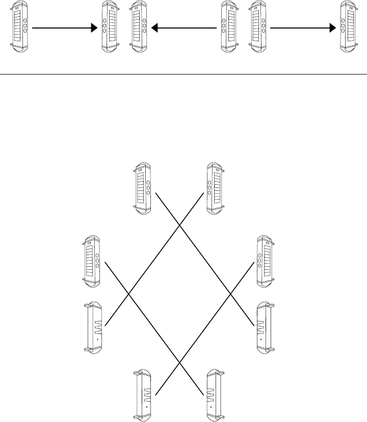
PERIMETER MOUNTING
FOR ALL MOUNTING SITUATIONS
In all mounting situations it is very important that the ‘A’ unit only interact with one ‘B’ unit or
the pair may not alert properly. Use the diagrams below for reference.
5
Receiver 2 (B) Transmitter 2 (A)
300 feet
Transmitter 1 (A) Receiver 1 (B)
300 feet
STRAIGHT LINE MOUNTING (900 feet)
Transmitter 3 (A) Receiver 3 (B)
300 feet
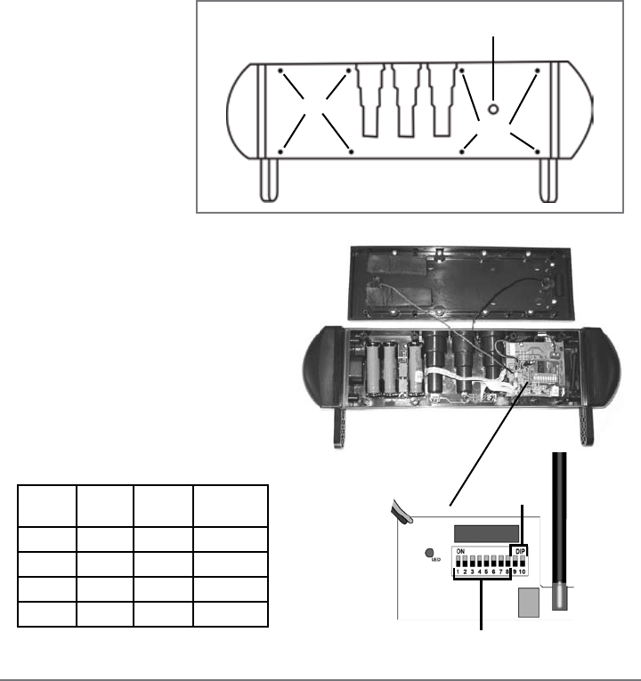
ONLY OPEN UNIT ‘A’ IF CHANGING THE ZONE/CHIME IS ABSOLUTELY NECESSARY. It is not
recommended to change any settings as the BBA-2500 is factory set to match.
DO NOT OPEN UNIT ‘B’.
Remove the 8 screws on
the back of unit ‘A’ (Fig-
ure 5-1). Gently lift the
solar panel to expose
the transmitter board
(Figure 5-2). Locate the
10 dip switches on the
red block.
The rst
eight dip switches are
for the frequency set-
ting (256 combinations). Set switches
1-8 to match the eight switches in the
receiver. Switches 9 and 10 are for the
zone/channel settings on the trans-
mitter. The four zones are listed in the
table below.
Coding the DCR-2500 receiver:
Open the receiver case by inserting a small screwdriver into one of the pry notches on the
side of the case (refer to receiver manual). Gently lift o the front cover. Locate the eight dip
switches on the DCR-2500 and make sure they are set identically to dip switches 1-8 on the
BBT-2500.
Note: If more than one transmitter is used with the receiver, the first eight dip switches of
all transmitters must match the eight dip switches of the receiver.
Note: Whenever a change is made to the time jumper or the dip switches, the receiver
must be turned OFF and then back ON to operate properly.
Switch
9
Switch
10
Channel
Tune
On On 1
Classical
O On 2
Westminster
On O 3
Ding Dong
O O 4 Whistle
Power Button
Screws
Screws
Back of unit
Figure 5-1
Figure 5-2
Change frequency
Change tone
Transmitter module
6

TROUBLESHOOTING:
If sensor pair alerts when originally paired, but will not alert when mounted...
1. Push power button on unit ‘A’
2. Look in center hole for the indicator light. If light is on, proceed to step 3. If light is not on, press
power button again. Indicator light should come on.
3. Repeat steps 1 and 2 for unit ‘B’. This will re-sync the units.
If experiencing false alerts...
• Check for obstruction (i.e. branch, frost)
• Extreme fog
• Extreme snow and rain
•
If obstruction/weather are not involved, try changing the frequency of the DCR-2500 and unit ‘A’
• If unit is blocked continually a second signal will be generated after one hour
If no signal...
• Turn power o on all units for 60 seconds and then turn power back on
• Make sure units are still aligned
• Make sure all 8 dip switches in DCR-2500 match the rst 8 dip switches inside unit ‘A’
TECHNICAL SUPPORT: If you encounter any diculty in the operation of this product after
reading the manual, please contact Dakota Alert. You can reach us by phone at 605-356-
2772 from 8:30 AM to 5:00 PM Monday through Friday (Central Standard Time). We will be
happy to answer your questions and help you in any way we can.
WARRANTY: Dakota Alert warrants this product to be free of defects in material and
workmanship for a period of one year from the date of purchase. This warranty does not
cover damage resulting from accident, abuse, act of God or improper operation. If this
product does become defective, simply return it to Dakota Alert. Please include a note
describing the troubles along with your name and return address as well as the original
sales receipt. If the product is covered under warranty it will be repaired or replaced at no
charge. If it is not covered by warranty, you will be notied of any charges before work is
done.
7
Dakota Alert, Inc.
32556 E. Main Street Phone: (605) 356-2772
P0 Box 130 Fax: (605) 356-3662
Elk Point, SD 57025 www.dakotaalert.com
