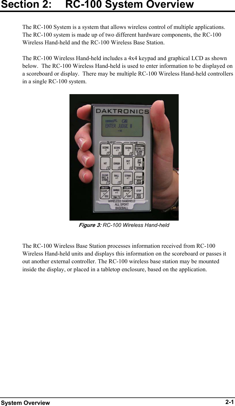
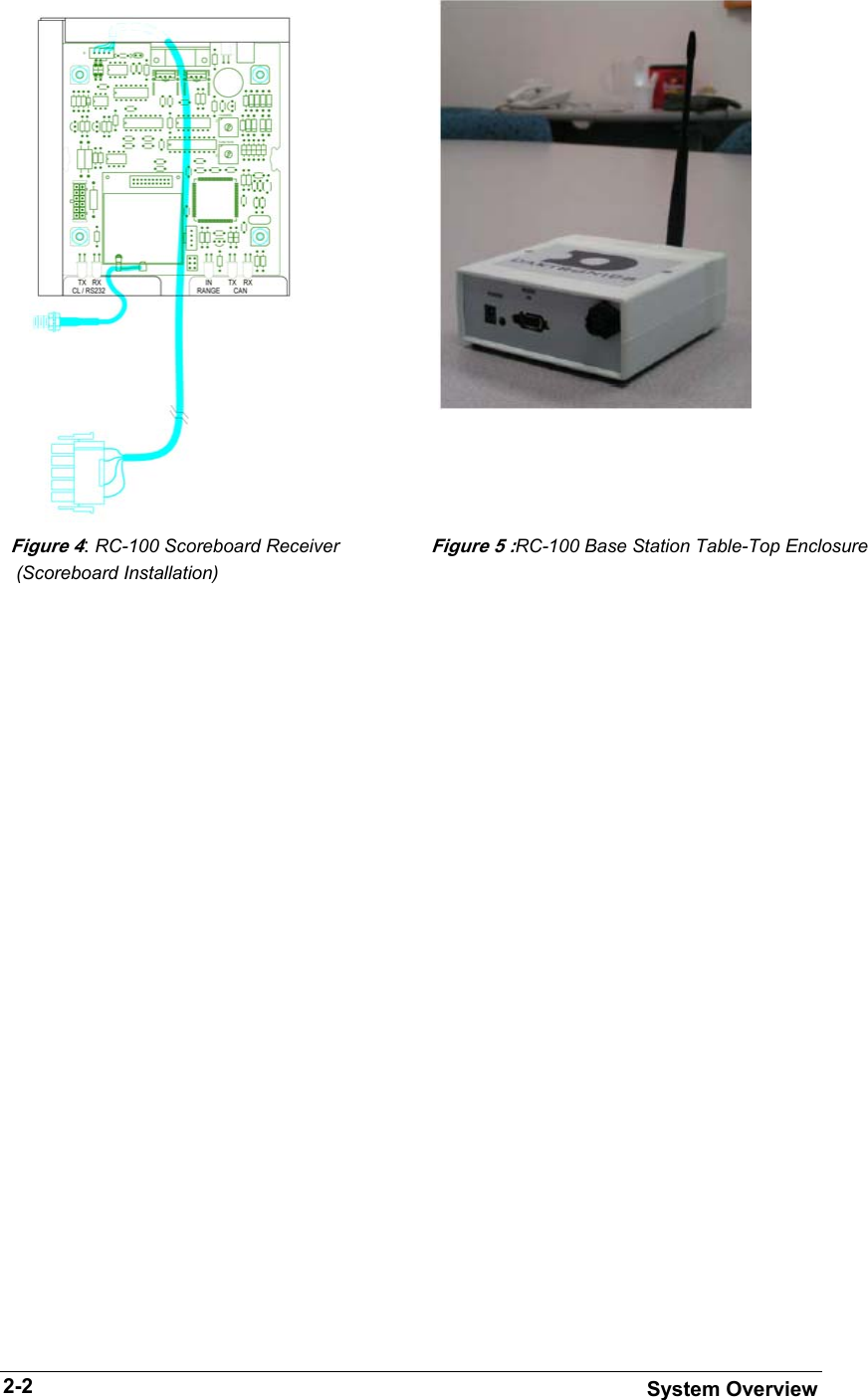
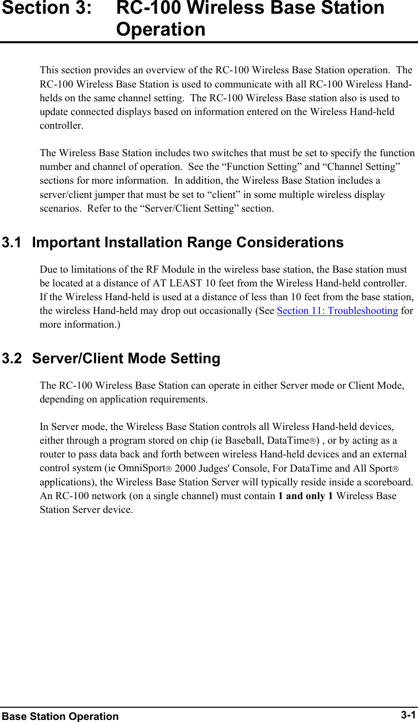
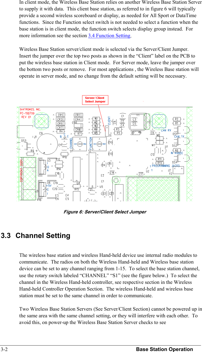
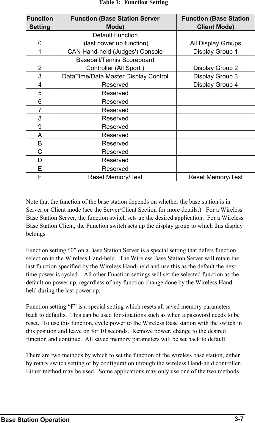
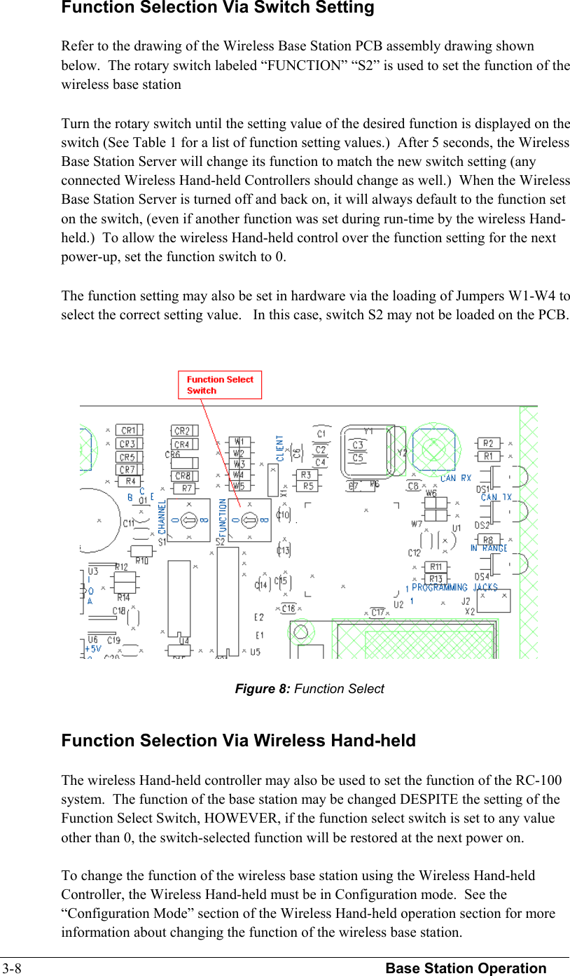
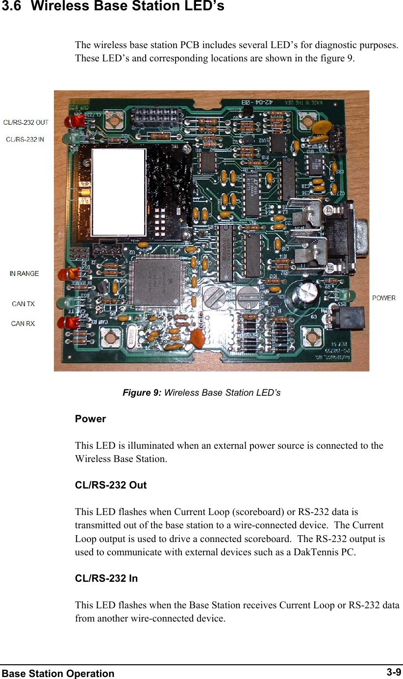
Daktronics 04262005P1110 Remote Control System User Manual ED 15133 REV0

Daktronics, Inc. Remote Control System ED 15133 REV0

Users Manual

  Remote Control System RC-100   Operational Overview  ED-15133                    Rev 0—18 March 2005
       ED-15133 Product 1110-07   Rev 0–18 March 2005                       DAKTRONICS, INC. Copyright  2005  All rights reserved. While every precaution has been taken in the preparation of this manual, the publisher assumes no responsibility for errors or omissions. No part of this book covered by the copyrights hereon may be reproduced or copied in any form or by any means – graphic, electronic, or mechanical, including photocopying, taping, or information storage and retrieval systems – without written permission of the publisher.  All Sport® , DataTime, OmniSport, ProStar® are trademarks of Daktronics, Inc. All other trademarks used in this manual are the property of their respective owners.
  Reproduction Reference ED15133- –P1110-07 Remote Control System RC-100, Operation and Maintenance Manual   1.  This page is for reproduction reference only and will not be included in the manual.  2.  This manual is to be copied on FRONT AND BACK PAGES -8 ½ x 11 paper.   3.  Note: The first page, Cover Page, uses the front of the page (blank on back). Section heading pages always start on a new page; they never start on the back of another page.  4.  Insert drawings, listed below, in alphanumeric order in Appendix A: Reference Drawings. Print A drawings back-to-back. Print B drawings as A-size.         5.  Use a blue window cover and a blue back. Punch all pages, window cover, and back cover along the left edge and bind with a binder.  6.  Please direct questions and suggestions to Engineering Support. A-230530      A-230608      A-231298      A-231674      A-233254
 Table of Figures    i  Table of Contents Section 1: Introduction.......................................................................................1-1 1.1 How To Use This Manual ......................................................................... 1-1 1.2 Daktronics Overview................................................................................. 1-2 1.3 Manual Overview ...................................................................................... 1-3 Section 2: RC-100 System Overview ................................................................2-1 Section 3: RC-100 Wireless Base Station Operation ......................................3-1 3.1 Important Installation Range Considerations ............................................ 3-1 3.2 Server/Client Mode Setting ....................................................................... 3-1 3.3 Channel Setting ......................................................................................... 3-2 3.4 Synchronizing Multiple Base Stations and Channel Selection.................. 3-3 3.5 Function Setting......................................................................................... 3-3 Function Selection Via Switch Setting...................................................... 3-8 Function Selection Via Wireless Hand-held  ............................................ 3-8 3.6 Wireless Base Station LED’s .................................................................... 3-9 Section 4: RC-100 Wireless Hand-held Controller  Operation .......................4-1 4.1 Fundamental Operations: Config or Connect Mode.................................. 4-1 4.2 Keypad: ..................................................................................................... 4-1 4.3 Wireless Hand-held Common Key Overview ........................................... 4-2 4.4 Powering the Controller On and Off ......................................................... 4-5 4.5 Battery Operation ...................................................................................... 4-6 4.6 Configuration Mode .................................................................................. 4-7 4.7 Configuration Menu .................................................................................. 4-8 Setting a default channel Number ............................................................. 4-8 Adjusting LCD Contrast:........................................................................... 4-8 Setting the Power On When Idle Time.................................................... 4-10 Scanning Channels .................................................................................. 4-10 Set Wireless Base Station Server Function ............................................. 4-12 4.8 Switching to Connect Mode .................................................................... 4-13 Section 5: Application Specific Overview – All Sport Applications ..............5-1 5.1 Selecting All Sport Applications (Code Numbers) ................................... 5-1 5.2 Notes about Code Selection....................................................................... 5-2 5.3 Common All Sport Application Keys........................................................ 5-2 Section 6: Baseball Operations ......................................................................... 6-1 6.1 Wireless Specific Considerations .............................................................. 6-1 6.2 Baseball Keys ............................................................................................ 6-2 Out +1, Inning +  ....................................................................................... 6-2 Ball, Strike, Clear Ball/Strike ................................................................... 6-3 Hit, Error  .................................................................................................. 6-3
ii    Table of Contents    Home/Guest Score +1, -1  ......................................................................... 6-4 Section 7: Tennis Operations ............................................................................ 7-1 7.1 Wireless Specific Considerations .............................................................. 7-1 7.2 Tennis Keys ............................................................................................... 7-2 TOD/Game ................................................................................................ 7-2 Serve.......................................................................................................... 7-2 Game +1 .................................................................................................... 7-2 Point........................................................................................................... 7-3 Tie Break ................................................................................................... 7-3 Reset Game................................................................................................ 7-3 Reset Match (Alternative Function) .......................................................... 7-3 Set +1......................................................................................................... 7-4 Team Score (Alternative Function) ........................................................... 7-4 Section 8: Application Specific Overview – CAN Hand-held ......................... 8-1 8.1 Common CAN Hand-held Operation ........................................................ 8-2 Section 9: Judges' Console Operations- Rodeo ............................................. 9-1 Section 10:   Judges' Console Operations-  Diving and Synchronized Swimming.................................................................... 10-1 Section 11: Troubleshooting ............................................................................. 11-1 11.1 Hand-held Error Messages ...................................................................... 11-1 11.2 Wireless Base Station Errors ................................................................... 11-3 Section 12: Orderable parts............................................................................... 12-1 Appendix A: Reference Drawings...................................................................... 12-A
 Introduction  1-1Section 1:  Introduction 1.1  How To Use This Manual This manual explains the operation and maintenance of the Daktronics RC-100 Remote Control System. For other questions regarding the safety, installation, operation, or service of these systems, contact Daktronics. Customer Service Help Desk telephone numbers are listed on the cover page of this manual.   Figure 1 illustrates the Daktronics drawing numbering system. Daktronics identifies individual engineering drawings by the drawing number (7087-P08A-69945 in the example), which is located in the lower right corner of the drawing. This manual refers to drawings by their last set of digits and the letter preceding them. The example would be Drawing A-69945.  Reference drawings are grouped and inserted in alphanumeric order in the Appendix.  Listed below are a number of drawing types commonly used by Daktronics, along with the information that each is likely to provide.   Schematics: power wiring, signal wiring, panel board or power termination panel assignments, signal termination panel assignments, and transformer assignments. Final Assembly: component locations, part numbers, display dimensions, and assembly/disassembly instructions.  All references to drawing numbers, appendices, figures, or other manuals are presented in bold typeface, as in this example: “Refer to Drawing C-209144 for information on the clip angle.” Additionally, any drawings referenced within a particular subsection are listed at the beginning of that subsection in the following manner:  Figure 1: Daktronics Drawing Label
Introduction  1-2 Reference Drawing:   Shop Dwg, Football SCBD w/ AF-3160 Video ............ Drawing C-209144  Daktronics identifies each manual by assigning an engineering document, or ED, number, which is located on the cover page. This manual, for example, would be referred to as ED-15133.  The serial and model numbers of a Daktronics scoreboard or equipment can be found on the ID label on the display. The label will be similar to the one shown in Figure 2. When calling Daktronics Customer Service, please have this information available to ensure that your request is serviced as quickly as possible. For future reference, note your scoreboard model number, serial number, and installation date on the front page of this manual. 1.2 Daktronics Overview To fully understand some Daktronics drawings, such as schematics, it is necessary to know how various components are labeled in those drawings. You will find this information useful when trying to communicate maintenance or troubleshooting efforts.  The label "A" on a drawing item typically denotes an assembly. An assembly can be a single circuit board or a collection of components that function together, usually mounted on a single plate or in a single enclosure.  In addition, the following labeling formats might be found on various Daktronics drawings:    "TB__" denotes a termination block for power or signal cable.   "F__" denotes a fuse.   "E__" denotes a grounding point.   "J__" denotes a power or signal jack.    "P__" denotes a power or signal plug for the opposite jack.  Finally, Daktronics part numbers are commonly listed on drawings. Those part numbers can be used when requesting replacement parts from Daktronics Customer Service. Take note of the following part number formats. (Not all possible formats are listed here.)    "0P-__-__" denotes an individual circuit board, such as a driver board.   "0A-__-__" denotes an assembly, such as a circuit board and the plate or bracket to which it is mounted. A collection of circuit boards working as a single unit may also carry an assembly label.  Figure 2: Daktronics Identification Label
 Introduction  1-3   "W-__" denotes a wire or cable. Cables may also carry the assembly numbering format in certain circumstances. This is especially true of ribbon cables.   "F-__" denotes a fuse.   "T-__" denotes a transformer.   "PR-___-_" denotes a specially ordered part.   "M-__" denotes a metal part, and "0M-____" typically denotes a fabricated metal assembly. 1.3 Manual Overview The RC-100 Remote Control System is used in several applications where a wireless Hand-held terminal is used to configure or control displays or systems.  This manual describes the configuration of the RC-100 Hand-held and RC-100  Base station
 System Overview  2-1Section 2:  RC-100 System Overview The RC-100 System is a system that allows wireless control of multiple applications.  The RC-100 system is made up of two different hardware components, the RC-100 Wireless Hand-held and the RC-100 Wireless Base Station.    The RC-100 Wireless Hand-held includes a 4x4 keypad and graphical LCD as shown below.  The RC-100 Wireless Hand-held is used to enter information to be displayed on a scoreboard or display.  There may be multiple RC-100 Wireless Hand-held controllers in a single RC-100 system.  The RC-100 Wireless Base Station processes information received from RC-100 Wireless Hand-held units and displays this information on the scoreboard or passes it out another external controller. The RC-100 wireless base station may be mounted inside the display, or placed in a tabletop enclosure, based on the application.    Figure 3: RC-100 Wireless Hand-held
System Overview  2-2   Figure 4: RC-100 Scoreboard Receiver           Figure 5 :RC-100 Base Station Table-Top Enclosure  (Scoreboard Installation)
 Base Station Operation  3-1Section 3:  RC-100 Wireless Base Station         Operation This section provides an overview of the RC-100 Wireless Base Station operation.  The RC-100 Wireless Base Station is used to communicate with all RC-100 Wireless Hand-helds on the same channel setting.  The RC-100 Wireless Base station also is used to update connected displays based on information entered on the Wireless Hand-held controller.  The Wireless Base Station includes two switches that must be set to specify the function number and channel of operation.  See the “Function Setting” and “Channel Setting” sections for more information.  In addition, the Wireless Base Station includes a server/client jumper that must be set to “client” in some multiple wireless display scenarios.  Refer to the “Server/Client Setting” section. 3.1  Important Installation Range Considerations Due to limitations of the RF Module in the wireless base station, the Base station must be located at a distance of AT LEAST 10 feet from the Wireless Hand-held controller.  If the Wireless Hand-held is used at a distance of less than 10 feet from the base station, the wireless Hand-held may drop out occasionally (See Section 11: Troubleshooting for more information.) 3.2  Server/Client Mode Setting The RC-100 Wireless Base Station can operate in either Server mode or Client Mode, depending on application requirements.  In Server mode, the Wireless Base Station controls all Wireless Hand-held devices, either through a program stored on chip (ie Baseball, DataTime) , or by acting as a router to pass data back and forth between wireless Hand-held devices and an external control system (ie OmniSport 2000 Judges' Console, For DataTime and All Sport applications), the Wireless Base Station Server will typically reside inside a scoreboard. An RC-100 network (on a single channel) must contain 1 and only 1 Wireless Base Station Server device.
3-2  Base Station Operation  In client mode, the Wireless Base Station relies on another Wireless Base Station Server to supply it with data.  This client base station, as referred to in figure 6 will typically provide a second wireless scoreboard or display, as needed for All Sport or DataTime functions.  Since the Function select switch is not needed to select a function when the base station is in client mode, the function switch selects display group instead.  For more information see the section 3.4 Function Setting.  Wireless Base Station server/client mode is selected via the Server/Client Jumper.  Insert the jumper over the top two posts as shown in the “Client” label on the PCB to put the wireless base station in Client mode.  For Server mode, leave the jumper over the bottom two posts or remove.  For most applications , the Wireless Base station will operate in server mode, and no change from the default setting will be necessary. 3.3 Channel Setting  The wireless base station and wireless Hand-held device use internal radio modules to communicate.  The radios on both the Wireless Hand-held and Wireless base station device can be set to any channel ranging from 1-15.  To select the base station channel, use the rotary switch labeled “CHANNEL” “S1” (see the figure below.)  To select the channel in the Wireless Hand-held controller, see respective section in the Wireless Hand-held Controller Operation Section.  The wireless Hand-held and wireless base station must be set to the same channel in order to communicate.    Two Wireless Base Station Servers (See Server/Client Section) cannot be powered up in the same area with the same channel setting, or they will interfere with each other.  To avoid this, on power-up the Wireless Base Station Server checks to see   Figure 6: Server/Client Select Jumper
 Base Station Operation  3-3if there are any other servers located nearby.  If another server is detected, the “In Range” LED on the server will flash quickly to indicate interference, and continue to flash until the channel is changed or the conflicting base station is turned off.    If two wireless base station server units need to operate at the same time in the same location, set each to an independent channel.  3.4  Synchronizing Multiple Base Stations and Channel Selection Channel one is the default channel used by Daktronics for single base-station installations.  When multiple base stations are installed in a single location, additional consideration must be given to channel number selection.  The RC-100 wireless system uses frequency hopping technology to maximize range and minimize interference from other systems.  When multiple base stations are installed within range of each other (approx 2000 feet) base stations must be able to synchronize with one another so that their hop sequences do not interfere with each other.  This is accomplished by the use of synch groups.  A list of the synch groups and their corresponding channel numbers and channel groups are shown in the table below.  Sync Group Channel Number Primary Channel Group Extended Channel Group10 All2 1 2,3,4,5 7,8,9,10,12 (C), 13 (D), 14 (E), 15 (F)3 6 7,8,9,10 12 (C), 13 (D), 14 (E), 15 (F)4 11 (B) 12 (C), 13 (D), 14 (E), 15 (F)   Figure 7: Channel Select Switch
3-4  Base Station Operation   The “Channel Number,”  “Primary Channel Group,” and “Extended Channel Group” entries correspond to the switch settings on the rotary channel switch and hand-held settings that pertain to the Sync Channel shown on the same line.  Each “Primary Channel Group” lists the channels that will attempt to synchronize to this synch channel as a first-choice.  If any base stations set to these “Primary Channels” are within range of a base station set to the corresponding sync channel number, the primary channel base station will sync to the corresponding sync channel.  The “Extended Channel Group” lists channels that attempt to synchronize to the corresponding sync channel as a second or third choice.  When these channels are not within range of their primary sync channel, they will attempt to synchronize to the corresponding sync channel.  When a base station is synchronized to a Sync Channel, the In Range LED will flash briefly approximately every 5 seconds with the number of times flashed corresponding to the sync group (1 = Channel 0, 2= Channel 1, 3=Channel 6, 4= Channel 11 (B).)   Any base stations set to channels in the “Channel Groups” section will continuously scan for sync base stations whenever no hand-held controllers are connected.  This will allow these boards to be powered up in any sequence and still obtain network synchronization.  If your installation includes a central base station installation location approximately 3000 feet or less from all other base stations which will remain on at all times during operation on any base station, a base station set to channel 1 may be installed in this location and all other base stations may be set to values in the primary and extended channel groups for this channel number.  An example is shown below for the case of a baseball diamond.
 Base Station Operation  3-5 If your installation does not include a central location as described previously, or if groups of base stations will be powered down at times other groups will need to be active, you will need to use sync groups 3 and 4 (channels 6 and 11.)  You may use sync groups 3 and 4 (channels 6 and 11) as synchronizing channels for two other independent groups of scoreboards that may or may not be in range of any other groups.  An example is shown below for a 3 independent group system.
3-6  Base Station Operation   An important limitation exists for channels 1,6, and 11.  Since other channels use these channels for synchronization purposes, base stations on these channels cannot scan during normal operation, only at power-up.  For this reason, these base stations must be powered up in-order (1 first, then 6, then 11) in order to maintain overall network synchronization in the case where Channels 1, 6, and 11 all need to be powered up at the same time. 3.5 Function Setting To configure the function of the RC-100 system, the desired system function must be configured in the Wireless Base Station.  A list of possible current functions are listed below along with the “function setting” used to reference the function.
 Base Station Operation  3-7Table 1:  Function Setting  Function Setting Function (Base Station Server  Mode) Function (Base Station Client Mode) 0 Default Function  (last power up function)  All Display Groups 1  CAN Hand-held (Judges') Console  Display Group 1 2 Baseball/Tennis Scoreboard  Controller (All Sport )  Display Group 2 3  DataTime/Data Master Display Control  Display Group 3 4  Reserved  Display Group 4 5 Reserved   6 Reserved   7 Reserved   8 Reserved   9 Reserved   A Reserved   B Reserved   C Reserved   D Reserved   E Reserved   F  Reset Memory/Test  Reset Memory/Test   Note that the function of the base station depends on whether the base station is in Server or Client mode (see the Server/Client Section for more details.)   For a Wireless Base Station Server, the function switch sets up the desired application.  For a Wireless Base Station Client, the Function switch sets up the display group to which this display belongs.  Function setting “0” on a Base Station Server is a special setting that defers function selection to the Wireless Hand-held.  The Wireless Base Station Server will retain the last function specified by the Wireless Hand-held and use this as the default the next time power is cycled.   All other Function settings will set the selected function as the default on power up, regardless of any function change done by the Wireless Hand-held during the last power up.  Function setting “F” is a special setting which resets all saved memory parameters back to defaults.  This can be used for situations such as when a password needs to be reset.  To use this function, cycle power to the Wireless Base station with the switch in this position and leave on for 10 seconds.  Remove power, change to the desired function and continue.  All saved memory parameters will be set back to default.  There are two methods by which to set the function of the wireless base station, either by rotary switch setting or by configuration through the wireless Hand-held controller.   Either method may be used.  Some applications may only use one of the two methods.
3-8  Base Station Operation   Function Selection Via Switch Setting  Refer to the drawing of the Wireless Base Station PCB assembly drawing shown below.  The rotary switch labeled “FUNCTION” “S2” is used to set the function of the wireless base station  Turn the rotary switch until the setting value of the desired function is displayed on the switch (See Table 1 for a list of function setting values.)  After 5 seconds, the Wireless Base Station Server will change its function to match the new switch setting (any connected Wireless Hand-held Controllers should change as well.)  When the Wireless Base Station Server is turned off and back on, it will always default to the function set on the switch, (even if another function was set during run-time by the wireless Hand-held.)  To allow the wireless Hand-held control over the function setting for the next power-up, set the function switch to 0.  The function setting may also be set in hardware via the loading of Jumpers W1-W4 to select the correct setting value.   In this case, switch S2 may not be loaded on the PCB.  Function Selection Via Wireless Hand-held  The wireless Hand-held controller may also be used to set the function of the RC-100 system.  The function of the base station may be changed DESPITE the setting of the Function Select Switch, HOWEVER, if the function select switch is set to any value other than 0, the switch-selected function will be restored at the next power on.  To change the function of the wireless base station using the Wireless Hand-held Controller, the Wireless Hand-held must be in Configuration mode.  See the “Configuration Mode” section of the Wireless Hand-held operation section for more information about changing the function of the wireless base station.   Figure 8: Function Select
 Base Station Operation  3-93.6  Wireless Base Station LED’s  The wireless base station PCB includes several LED’s for diagnostic purposes.  These LED’s and corresponding locations are shown in the figure 9.     Figure 9: Wireless Base Station LED’s  Power  This LED is illuminated when an external power source is connected to the Wireless Base Station.  CL/RS-232 Out  This LED flashes when Current Loop (scoreboard) or RS-232 data is transmitted out of the base station to a wire-connected device.  The Current Loop output is used to drive a connected scoreboard.  The RS-232 output is used to communicate with external devices such as a DakTennis PC.  CL/RS-232 In  This LED flashes when the Base Station receives Current Loop or RS-232 data from another wire-connected device.
3-10  Base Station Operation  In Range  On a Base Station Server, this LED flashes several times at startup to show that the base station is searching for other base station servers on the same channel within range.  If another base station server is found, this LED will flash continuously, indicating that only one base station server is allowed on a given channel.  Once the Base Station server has entered operation mode, this LED indicates whether or not a Hand-held device is currently connected.  When one or more Hand-held devices are connected, the In Range LED will be on.  When no Hand-held devices are connected, the In Range LED will be off.  On a Base Station Client, this LED is on whenever the client is connected to a Base Station Server.  In addition, the In Range LED is also used to show base station synchronization status.  When the base station is synchronized to another base station using a synch group, the sync group number is flashed on the LED approximately once every 5 seconds.  For more information, refer to the Synchronizing Multiple Base Stations and Channel Selection Section.  CAN TX  The CAN TX LED illuminates (flashes) when CAN (Controller Area Network) data is transmitted to a connected CAN device such as the Omnisport 2000.  CAN RX  The CAN RX LED illuminates (flashes) when CAN (Controller Area Network) data is received from a connected CAN device such as the Omnisport 2000.  LED Error Diagnostics  The CAN TX, In Range, CL/RS-232 Out and CL/RS-232 in are also used to display errors that occur in Wireless Base Station Operation.  Please refer to Wireless Base Station Errors for more information.
 Handheld Controller Operation  4-1 Section 4:  RC-100 Wireless Hand-held Controller Operation 4.1  Fundamental Operations: Config or Connect Mode The Wireless Hand-held Controller always operates in one of two modes, Connect Mode or Config Mode.    Connect mode is used when the Wireless Hand-held is Connected to a Wireless Base Station Server.  In Connect mode, the operation of the Hand-held is determined by the Wireless Base Station, and all operation is specific to the Wireless Base Station Function selected.  Config (short for “configuration”) mode is used when a Wireless Hand-held is not being controlled by a Wireless Base Station Server.  Config mode is used to setup operational parameters in the Wireless Hand-held controller, such as which channel to use or the amount of time to run idle before turning off.   The icon below is shown on the LCD when the controller is in Connect mode: The following icon is shown on the top left of the LCD when the controller is in Configuration mode:  Refer to the following sections for more information about each of these modes. 4.2 Keypad: The default layout of the wireless Hand-held keypad is shown below.  This drawing will be referenced in the following operational sections.  Note that the actual keypad for the user-connected application will vary, and will include any text specific to that application.  However, all applications will have this default keypad layout in configuration mode.   Figure 10: Connect Mode LCD Icon  Figure 11: Config Mode LCD Icon
4-2    Handheld Controller Operation  4.3  Wireless Hand-held Common Key Overview Several keys on the default keypad layout may be common to multiple Wireless Hand-held applications.  These keys are described in the following section.  For a description of the function of keys for a specific application, please see the Application specific section of the manual.  Wireless Hand-held Control Keys   Some keys on the keypad are included on all keypads specifically for the purpose of controlling Wireless Hand-held configuration.  These keys are marked by inverted text, such as “ON/OFF” “CONFIG” or “CONNECT.”  These keys may or may not be used during wireless Hand-held connect mode operation (see the application specific section for more information.)  On/Off Key  This key is used to turn the Wireless Hand-held Controller On or Off.   See the section “Powering the Controller On and Off” for more information.  Config Key  This key is used to switch to configuration mode and enter the configuration menu for the Wireless Hand-held.  See the “Configuration Mode” section for more information.  Figure 12: Common RC-100 Keys
 Handheld Controller Operation  4-3Connect Key  This key may be used to connect to a Wireless Base Station, after the correct channel number has been configured.   See the “Configuration Mode” section for more information.  This key may be used to connect to a Wireless Base Station, after the correct channel number has been configured.   See the “Configuration Mode” section for more information.  Pressing “Alt” followed by the “Connect” key when a connection is made to a wireless base station will show base station synchronization and revision information.  See Troubleshooting: Obtaining Base Station Status Information for more details.  Arrow Up/Down Keys  These keys are used to navigate through the configuration menu in Configuration Mode.  These keys may also be used in applications for specific functions.  See the Configuration Mode or application specific sections for more information.  Alt Function Keys    The Bottom Left key on the keypad labeled “ALT” is used to run alternate functions on a specified key.  The Alternate key function, if applicable, will be shown on the  key in the bottom half of the key below a horizontal line.  See the Example below for the “Set Time/Up/DN” key. The Horizontal line separating  <SET TIME> from <UP/DN> indicates that the alternate function for this key is  <UP/DN> Which sets the clock direction as count up or count down.  If the <ALT> Key is pressed before pressing this key, the “UP/DN” key function will be run.  If the <ALT> key was not pressed, pressing this key selects the “Set Time” function.   See the Application Specific section for your product for more information about the use of <ALT> function keys.  Figure 13: Set Time Up/Dn Key
4-4    Handheld Controller Operation   The Edit Key     The Edit key is used to edit data associated with a specific key.  An example is shown below for the “Out +1” key (Baseball specific.) Normally when the Out+1 Key is pressed, the number of outs will increment by one.  However, in the case it is desired to change the value using the number key, press <EDIT> <OUT+1>.  An LCD display will allow you to edit the current out value using the number keys on the keypad.  See the Application specific section for more information about the use of the <EDIT> key.  Number Keys  Number keys are used for numeric entry functions.  The key itself may be used for other key functions normally, but when in an edit routine, this key may be used to enter the number shown in the bottom right corner of the key.  ON/OFF Clear/No Alt Key  This key has several functions.  The ON/OFF function is described in the section “Powering the Controller ON and OFF    The ALT function is described in the “ALT Function Keys” section.  This is the key that selects Alternate functions for application keys.  Press this key before pressing the alternate function key to select the alternate function for that key. The <NO> operation of this key pertains to editing and data entry routines.  When a question prompt is shown on the LCD with a Question mark, The <NO> key answers this question with a “NO.”  The <CLEAR> operation of this key pertains to editing and data entry routines.  When editing a value, pressing the <CLEAR> key clears that value.  This key can be used to blank items on the display, by entering an edit routine for that  Figure 14: Out+1 Key  Figure 15: General Number Key
 Handheld Controller Operation  4-5item, pressing the <CLEAR> key, and pressing the <ENTER> key to accept the cleared state.  The <CLEAR> key may also be used to escape out of an editing function.  If a key was pressed inadvertently, or if you would not like to change the value being edited, pressing <CLEAR> twice exits the editing routine without modifying the value. Config Enter/Yes Edit  This key has several functions.  The <CONFIG> function is described in  the “Wireless Hand-held Control Keys” section.  The <EDIT> key is described in the “Edit Key” section. Use this key to edit the data associated with a particular key (see application section for more information.)    The <YES> function of this key pertains to editing and data entry routines.  When a question is shown on the LCD with a question mark, this key answers this question with a “YES.”  The <ENTER> function of this key pertains to editing and data entry routines.  When you have completed editing a value, press the <ENTER> key to accept the change and update on the display (if applicable.) 4.4  Powering the Controller On and Off The wireless Hand-held controller is a battery-powered device.  When using battery power, the controller shuts itself off or “sleeps” automatically after a period of inactivity.  Two methods may be used to “wake up” the Hand-held controller. Using External Power  Plugging the unit into an AC or DC power source via the power connector will turn on the wireless Hand-held controller and charge its internal batteries (see Battery Operation.)     Figure 16: ON/OFF Clear/No Alt Key  Figure 17: Enter/Yes Key
4-6    Handheld Controller Operation  Using the Keypad to Power On/Off  The bottom-leftmost key is labeled <ON/OFF>  Press and hold this key momentarily to turn on the controller.  If the controller LCD does not display initialization text within a few seconds, the internal battery is most likely dead (see Battery Operation.)  The controller may be turned off by either waiting for an inactivity timeout to turn the device off automatically, or by pressing and holding the <ON/OFF> key for 5 seconds.  The LCD will display a power down message after the key has been held for five seconds.  Release the <ON/OFF> key to turn the controller off.   Note, the Wireless Handheld will not turn off if connected to external power.  When connected to external power, the Wireless Handheld controller will remain on to monitor battery charging.  When external power is removed and charging is complete, the handheld will power down after a 5 second prompt to conserve battery power.  Press a key during the prompt after disconnecting external power to keep the handheld controller powered on. 4.5 Battery Operation A charger is contained inside the unit for re-charging the batteries.  To recharge the batteries when not in use, simply connect a 12V AC or DC power source to the power connector on the wireless Hand-held controller   A charger is contained inside the unit for re-charging the batteries.  To recharge the batteries when not in use, simply connect a 12V AC or DC power source to the power connector on the wireless Hand-held controller.   Figure 18: power source to the power connector  If desired, the wireless Hand-held controller may be run on external power.  Simply continue operation with external power connected.
 Handheld Controller Operation  4-7The current external power detect status is shown by the indicator on the top left corner of the LCD.  When external power is connected, a power plug will be shown to the right of the battery.   The indicator on the top left center of the LCD shows the battery status.  When the battery status indicator cycles from low to high and back to low again, the charger is in fast charging mode.  A completely discharged battery will take approximately 1 ½ hours of fast charging to completely recharge. 4.6 Range Indicator The top line of the LCD is used to show a range indicator, to determine the approximate signal strength of the network connection.   The antenna indicator on the left is shown when a base station is detected in range of the handheld.  Each successive bar indicates an additional level of signal strength between the handheld and base station.  When 0 or 1 bar is shown, the connection to the wireless network is likely to be limited, and the console may occasionally fail to respond.  To improve signal strength, move within range of the base station and remove any line-of-sight obstacles located between the base station and handheld controller.  Ideally, the handheld controller should have a clear line-of-sight to the base station antenna.  For more information see, Section 11 Troubleshooting   Figure 19: Signal Strength 4.7 Configuration Mode The wireless Hand-held controller operates in one of two different modes at all times, Configuration (Config) mode or Connect Mode.  When in Configuration Mode, the Wireless Hand-held is not being controlled by a Wireless Base Station Server.  This mode can be used to set Wireless Hand-held parameters such as function and power on time.  The current controller mode (Configuration or Connect) is shown on the top left corner of the LCD at all times.    Configuration mode may be entered from Connect mode by pressing and holding the <CONFIG> key for 5 seconds.  If the Wireless Hand-held has not yet been configured for a specific channel, the Configuration mode will automatically when the device is first powered on.  Otherwise, the Wireless Hand-held will attempt to connect at the last connected channel.   Figure 20: External Power Detect Status
4-8    Handheld Controller Operation  When in Configuration mode, a connection may be made to a specific wireless Hand-held controller via the <CONNECT> key, or Hand-held configuration items may be set by navigating through the Configuration Menu (See The Configuration Menu section.)  Pressing the <CONFIG> key when the controller is in Connect mode will display configuration options.  Use the up or down arrow keys to move through the possible configuration items.  Press the <ENT> key to modify a configuration item. 4.8 Configuration Menu  A list of the Configuration Items in the Configuration Menu and their description is shown below, in the order in which they occur in the configuration list.  The Configuration Menu is accessed by entering Config mode (Holding the <CONFIG> key down for 5 seconds.)  Setting a default channel Number  LCD Display  Action    Press ent to Set channel Press <ENTER> to set the default connect channel number.   Press the Arrow Up or Arrow Down key to move to a different configuration selection.   Use the number keys to enter the desired channel number.  The channel number should match the setting on the wireless base station for which you would like to connect to on power-up.   NN = Channel Number Default : 1  RADIO CHANNEL DEFAULT: nn*  Use the number keys to enter the desired channel number.  The channel number should match the setting on the wireless base station for which you would like to connect to on power-up.  Press <ENTER> when complete to save the setting.   Adjusting LCD Contrast:  LCD Display  Action    Press ent to Set cONTRAST Press <ENTER> to modify the default LCD contrast. Press the Arrow Up or Arrow Down key to move to a different configuration selection.
 Handheld Controller Operation  4-9LCD Display  Action     CONTRAST UP -  ↑  Contrast dn -    ↓  Use the up or down arrow keys on the keypad to set the desired contrast.  Press <ENTER> when complete to save the setting.
4-10    Handheld Controller Operation   Setting the Power On When Idle Time  LCD Display  Action    Press ent to Set PWR ON TIME Press <ENTER> to modify the default LCD Power On When Idle time.  This is the amount of time (in minutes) the wireless Hand-held will remain on when not in use.  Decrease this value for longer battery life.  Increase this value if the console needs to be inactive for longer periods of time without turning off.   NN = Channel Idle Power On Time.  Default: 20 minutes  IDLE PWR ON TIME CURRENT  NN*  Use the number keys to edit the idle power on time.  Press <ENTER> when complete to save the new setting.   Scanning Channels  LCD Display  Action    Press ent to SCAN CHANNELS Press <ENTER> to scan channels in search of Wireless Base Station Controllers that are currently functional.  This function is useful when one or more Wireless Base Station controllers are set to unknown channels.    NN = current channel  CHANNEL SCAN CHANNEL NN  When in the scan channels function, the Hand-held scans each channel one-by-one to determine the presence/absence of an RC-100 controller.  The current channel being scanned is shown on the bottom line of the LCD.  Please allow several seconds for each channel to be scanned.   N= the # of networks found CC = the Channel number of the current network SS = The signal strength of the current network (0 = none, FULL = full signal  N networks ↑↓ Ch: CC SS: SS  If the channel scan found wireless networks, the Hand-held will show each network found with a corresponding channel number and signal strength.  Use the up or down arrow keys to move through the different networks found during the channel scan.
 Handheld Controller Operation  4-11LCD Display  Action strength.)       ENT TO CONNECT ↑↓ NEXT NETWORK  If the channel scan found wireless networks, this message will flash on the LCD after showing the channel and signal strength for the current network.  You may direct the Hand-held to connect to the current network by pressing the <ENTER> key.     No networks found Press ent to Re-scan  If no wireless networks were found by the scan, you may press the <ENTER> key to re-scan the network.  Make sure you have a base station powered up and within range limits.  Please see Section 11 Troubleshooting
4-12    Handheld Controller Operation   Set Wireless Base Station Server Function  LCD Display  Action    Press ent to SET FUNCTION Press <ENTER> to set the function of the Wireless Base Station Server for the current power-up.  If the Wireless Base Station Server is set to Function Switch setting “0,” the function set by the Hand-held will be restored on the next power up.  Otherwise, the Base Station will use the function set on the switch as the function to use on the next power cycle.     ERROR – MUST BE CONNECTED  This prompt is shown when the function was attempted to be changed without being connected to a Wireless Base Station.  A Connection must first be made to the Wireless Base Station using the <CONNECT> key.   XXXXX – New Function    Change function Xxxxxxxxx  ↑↓  Use the up or down arrow keys to select the new function.  Press <ENTER> to confirm the selection and set the base station operation to this selected function.       Function changed  Connect? Wait for base  Station restart FUNCTION CHANGED   If the Function was able to be changed on the base station, the following LCD prompts are shown.  After the Function is changed, the base station must restart.  When the base station has re-started, press <YES> to re-connect to the base station.
 Handheld Controller Operation  4-13 4.9  Switching to Connect Mode After all initialization is complete, Press the <CONNECT> key to attempt to connect to a Wireless Base Station Server and switch to connect mode.  The LCD shows the current connection status.  The wireless Hand-held will attempt to connect to an RC-100 network at the channel setting selected by the default channel (set in the Configuration Menu.)   LCD Display  Action   NN = Current Channel setting  INITIALIZING RADIO  Connecting via Channel nn*  After pressing the <CONNECT> key, the Wireless Hand-held attempts to connect to the Wireless Base Station on the channel shown.    The Wireless Base Station must be powered on and must be set to the specified channel.  If a connection was made, the Wireless Hand-held will now be operating in Connect mode.  Refer to the application section for connection specific operation details.  If a connection could not be made, refer to Section 11: Troubleshooting for information about how to resolve the problem.
 AllSport Applications  5-1 Section 5:  Application Specific Overview – All Sport Applications This section describes information specific to All Sport applications.  The “All Sport” function is one of the functions provided by the RC-100 Wireless Base Station Server. All sections following this section describe All Sport Specific Applications 5.1  Selecting All Sport Applications (Code Numbers) To select a specific All Sport application (such as Baseball, Tennis, etc) the “All Sport” function must first be set in the Wireless Base Station Server.  For more information about selecting a function in the Wireless Base Station Server, please see Section 3.5 Function Setting” To set or modify the Wireless Base Station Server function using the Wireless Hand-held, see Section 3.3 Server/Client Mode Setting.  Once the All Sport function has been selected, the All Sport Application may be selected by entering a code number on the console.  Each application is selected by entering a specific code number.  This number may be found either in application specific documentation sections, or typically on the bottom center of the keypad insert.   LCD Display  Action  NN = Current Code Number XXXXX = Current Application      ENTER CODE NN XXXXXXXX ENTER CODE NN Not found  Enter the code number corresponding to the application you would like to run using the number keys on the keypad.  When the code number is correctly selected, the text describing the All Sport Application will be shown on the bottom line of the LCD.  Code numbers may typically be found by looking at the keypad insert  (bottom center) tab for the sport you would like to run.   “NOT FOUND” is shown on bottom line of the LCD if the specified code number was not available.  This typically means either the code number was entered incorrectly or the Base Station Firmware does not support this sport code.  If this is a new code number that your Base Station does not yet support, the Base Station will need to be either replaced or reprogrammed.  Contact Daktronics Customer Service.
5-2  AllSport Applications   5.2  Notes about Code Selection Since the Wireless Base Station Server is typically used with a single application, once the code number has been set the Wireless Base Station server will continue to use the same code number each time power is reset.  To change code numbers, use the NEW CODE key on the Wireless Hand-held (see the Common All Sport Application Keys section.)   5.3  Common All Sport Application Keys Some keys on the keypad, when used with an All Sport Application, provide the same types of features.  The following section contains a description of these keys.  Note, for common Wireless Hand-held keys, see the following section:  4.3 Wireless Hand-held Common Key Overview  New Code Key  This key is used to select a new code number in order to change the All Sport Application.  This key is typically implemented as an Alternate function  (the <ALT> key must be pressed before accessing.)   For more information about Alternate functions, see Alt Function Keys  This key may also provide an application defined function (a function listed in the top half of the key.)  Please see the Application specific section for more information        New Game  Figure 21 LCD Display  Action      Press ent to Select new code  Press the <ENTER> key to select a new code number.  Note, all game data for the current application will be lost.  Press <CLEAR> to resume normal operation.  If <ENTER> is selected, see the section 5.1 Selecting All Sport Applications (Code Numbers) to select the new code number
 AllSport Applications  5-3 e Key  This key is used to reset all current game data for a specific application.  This key would be used in preparation for a new game, when all current game data needs to be removed from the display. LCD Display  Action      Press ent to Select new Game  Press the <ENTER> key to start a new game.  Note, all game data for the current or last game in progress will be lost.  Press <CLEAR> to resume normal operation.     Figure 22:
 Baseball Operations  6-1 Section 6:  Baseball Operations Sport Insert LL-2605 (Code 03)  Reference Drawings:    System Riser Diagram; RC-100 Baseball/Tennis.....................Drawing A-230530  The system riser drawing is located in Appendix A and you can view the sport keypad insert drawing at the end of this section .If an insert is lost or damaged, a copy of the insert drawing can be used until a replacement can be ordered.  Refer Section 2 RC-100 System Overview for information on starting the console and for instructions for use of the sport insert. Read the Section 2 RC-100 System Overview material carefully to fully understand the following operating instructions.   If you do not know the code number to enter for your scoreboard, refer to 5.1 Selecting All Sport Applications (Code Numbers) in this manual. If you do not know the model number of your scoreboard, refer to the scoreboard installation and maintenance manual provided with the scoreboard. 6.1  Wireless Specific Considerations Although Multiple Wireless Hand-held Controllers may be connected to a single Wireless Base Station Server, the Baseball application allows only one Hand-held device to be connected at a time.   LCD Display  Action  ERROR - ANOTHER   Console DETECTED   Turn connected Console off    This message is displayed if another console is currently connected to the Wireless Base Station Controller.  This application does not permit multiple Wireless Hand-held controllers to be connected to a single Wireless Base Station Server.  Turn off the power to the currently connected device to continue operation.
6-2 Baseball Operations   6.2 Baseball Keys Out +1, Inning +1 The <OUT +1> and <INNING +1> keys are used to increment their respective totals.   LCD Display  Action  Inning +1    nn  nn = current setting  Press <OUT +1> or <INNING +1> to increment their respective totals.  The LCD shows which key was pressed and the new value.  To change values, first press <EDIT> and <OUT +1> or <INNING +1> to display the current setting. Enter the correct number on the number pad and press <ENTER*>.   Set Time The <SET TIME> key is used to set or adjust the game time.   LCD Display  Action  TIME EDIT        SET   CURR         60:00*   Press the < SET TIME > key and enter the desired time and then press <ENTER>.  CLOCK  running           57:25   If the < SET TIME > key is pressed when the clock is on the LCD will show that status as shown here  UP/DN (Alternate Function)  LCD Display  Action  Main Clock-Downv1-up     2-down   Press the < ALT > key and then the< UP/DN > key. The current direction is shown. Select the direction by pressing 1 or 2 or press <CLEAR> to abort.
 Baseball Operations  6-3 Start, Stop Press the  <START> key to start the game clock. Press the <STOP> key to stop the game clock.  DIM (Alternate Function)  LCD Display  Action  DIMMING 1level (0-3): None 0=NONE 1=2/3 2=1/2 3=1/3   Press the < ALT > key and then the< DIM > key. The current level is shown and can be changed by pressing a number key 0-3.  Ball, Strike, Clear Ball/Strike The <BALL +1> and <STRIKE+1> keys increment the ball and strike digits. Pressing the <CLEAR BALL & STRIKE>key clears the digits.    Note:   If the ball count value is 4 when <BALL +1>  is pressed, the value is blanked out.    If the strike count value is 3 when < STRIKE +1> is pressed, the value is blanked out.  LCD Display  Action  ball: +1 n                 Press the <BALL +1> or < STRIKE +1> to increment the ball and strike digits.   Press the <CLEAR BALL & STRIKE> key to clear the digits to zero.   Hit, Error The <HIT> and <ERROR> keys are used to turn on the Hit or Error indicator or digits in the table that follows, <ERROR> is used as an example.  LCD Display  Action   error: ON   Press the <HIT> or <ERROR> key to turn on the hit or error indicator or digits.   This display appears briefly.
6-4 Baseball Operations   Home/Guest Score +1, -1 The <HOME SCORE +1> and <HOME SCORE -1> and <GUEST SCORE +1> and <GUEST SCORE -1> keys are used to increment or decrement their respective totals.   LCD Display  Action  team score: +1    HOME        nn  nn = current setting  Press the appropriate home or guest <SCORE +1> or  <SCORE -1> key to increment or decrement the total number of runs for the team. The LCD shows which key was pressed and the new value for the corresponding team.  The <EDIT> key permits the user to select and edit Runs +1 or –1. First, press <EDIT> and the key for the home or guest field to be edited, then enter the correct number on the number pad and press <ENTER*>.    Figure 23: Baseball Overlay
 Tennis Operations  7-1 Section 7:  Tennis Operations Sport Insert LL-2607 (Code 08)  Reference Drawings:    System Riser Diagram; RC-100, Dak Tennis Config................Drawing A-231298 System Riser Diagram; RC-100 Baseball/Tennis.....................Drawing A-230530 System Riser Diagram; RC-100 SCBD Receiver Base St. ......Drawing A-233254  The system riser drawing is located in Appendix A,  there is also a drawing of the sport keypad insert. If an insert is lost or damaged, a copy of the insert drawing can be used until a replacement can be ordered.  Refer to Section 2 RC-100 System Overview for information on starting the console and for instructions for use of the sport insert. Read the Section 2 RC-100 System Overview material carefully to fully understand the following operating instructions.   If you do not know the code number to enter for your scoreboard, refer to 5.1 Selecting All Sport Applications (Code Numbers) in this manual. If you do not know the model number of your scoreboard, refer to the scoreboard installation and maintenance manual provided with the scoreboard. 7.1  Wireless Specific Considerations Multiple Wireless Hand-held Controllers may be connected to a single Wireless Base Station Server in the Tennis application. Each Hand-held device connected will control a specific court and the court number is selected when powered up  LCD Display  Action  ENTER COURT NUMBER    01   ERROR-Court Taken    This message is displayed whenever console is powered up and connected to the Wireless Base Station Controller.  If the court number entered has already been selected this error message will display
7-2 Tennis Operations 7.2 Tennis Keys TOD/Game The <TOD/GAME> key toggles the console between displaying Game Time or Time of Day (TOD). It also allows the user to change the time of day.  Press <TOD/GAME> to display the Time of Day prompt if the display is currently showing Game Time. If Time of Day is currently displayed on the console, it will change to Game Time.  LCD Display  Action  hh:mm:ss = current setting  SEC time of day 12:00:00*  Enter the time of day in hours, minutes, and seconds using the selected format on the number pad and press <ENTER*>.  The time of day clock is now displayed, if the scoreboard has that capability.   Serve  LCD Display  Action  TOP SERVE ON     <SERVE> turns the serve indicators on or off for the respective player.     Game +1  LCD Display  Action  GAMES WON +1 TOP N   Press <GAME +1> to increment the number of games won in the current set for the respective player.  To change values, first press <EDIT> and <GAME +1> to display the current setting. Enter the correct number on the number pad and press <ENTER*>.
 Tennis Operations  7-3  Point  LCD Display  Action  top = 15   bot = 30 set 1   t = 1   b = 2   The <POINT> key increments the point value for the respective player. If Tie Break scoring mode is selected, the points will increment by 1. Otherwise, the points will increment as 15, 30, 40 AD or GA. The current point values will be shown on the LCD.   Tie Break The <TIE BREAK> key sets the mode of scoring to Tie Break mode. In Tie Break scoring mode, points for each player are incremented by one when the <POINTS> key is pressed.   Note:    Tie Break scoring mode may only be selected when both player point values are 0.    To change scoring mode back to normal, use the <RESET GAME > key. Reset Game  Press <RESET GAME> to reset the player points values for the current game.  Reset Match (Alternative Function)  LCD Display  Action  Press enter to Start new match    The <MATCH> key will reset the current match. Press the <ALT> and then the <MATCH> key. Press <ENTER*> to reset the current match.   All set scores and the current game score will be cleared, and the set number will be set to 1.
7-4 Tennis Operations Set +1   LCD Display  Action  TOP = 15   BOT = 30 SET 2   t = 0   b = 0 nnn = current setting   Press <SET +1> to increment the current set number. The new set number and new set games won values will be displayed on the LCD.  To change values, first press <EDIT> and <SET +1> to display the current setting. Enter the correct number on the number pad and press <ENTER*>.   Team Score (Alternative Function)   LCD Display  Action  matches won edit  top n* n = current setting   The <MATCHES WON> key will edit the matches for the team. Press the <ALT> and then the <MATCHES WON> key. Enter the current team score and press <ENTER*>.  Set Time The <SET TIME> key is used to set or adjust the game time.   LCD Display  Action  TIME EDIT        SET   CURR         60:00*   Press the < SET TIME > key and enter the desired time and then press <ENTER>.  CLOCK  running           57:25   If the < SET TIME > key is pressed when the clock is on the LCD will show that status as shown here
 Tennis Operations  7-5 Alternate Function  LCD Display  Action  Main Clock-Downv1-up     2-down   Press the < ALT > key and then the< UP/DN > key. The current direction is shown. Select the direction by pressing 1 or 2 or press <CLEAR> to abort.  Start, Stop Press the  <START> key to start the game clock. Press the <STOP> key to stop the game clock.  DIM (Alternate Function)  LCD Display  Action  DIMMING level (0-3): None 0=NONE 1=2/3 2=1/2 3=1/3   Press the < ALT > key and then the< DIM > key. The current level is shown and can be changed by pressing a number key 0-3.  Figure 24:  Tennis Overlay
 CAN Handheld  8-1 Section 8:  Application Specific Overview – CAN Hand-held This section describes operation details specific to CAN (Controller Area Network) Hand-held operations.  CAN Hand-held functionality is used when Hand-held operation is controlled by a device on the CAN network such as the Omnisport 2000.   For information about how to select CAN Hand-held functionality or for general information about wireless Hand-held or base station operation, see Section 3 RC-100 Wireless Base Station Operation or Section 4 RC-100 Wireless Hand-held Controller Operation.  For information about All Sport Applications, see Section 5 Application Specific Overview – All Sport Applications.  For information specific to specific CAN Hand-held Applications, see the application sections following this section   Figure 25: CAN Hand-held Operation Example
8-2 CAN Handheld 8.1  Common CAN Hand-held Operation  LCD Display  Action  Waiting for External Control     When this prompt is shown on the LCD, the base station is waiting to be connected to an external device on the CAN network.  When a CAN device is detected, the LCD will update to show application specific information.  Figure 26: CAN Judge’s Console Overlay
 Judges Console Operations- Rodeo  9-1 Section 9:  Judges' Console Operations- Rodeo Please refer to the Judges' Console section of the Omnisport 2000 Rodeo Timer Operations manual (ED-14843) Figure 27:  CAN Rodeo Judges' Console Overlay
 10-1  Judges Console Operations Diving and Synchronized Swimming  Section 10:  Judges' Console Operations-Diving and Synchronized Swimming Please refer to the Omnisport 2000 Manual, ED-13312 for more information.   Figure 28: Diving and Synchronized Swimming Overlay
 Troubleshooting  11-1  Section 11:  Troubleshooting  11.1  Hand-held Error Messages When a Wireless Hand-held is unable to connect to a base station, the LCD display will show one of the following error messages.  Please refer to the “Action” section for information about how to resolve these errors.”  LCD Display  Action  NN = Current Channel           NO SERVER FOUND ON CHANNEL NN  Ent to retry Clear sets chan   The Wireless Hand-held could not find a server on the specified channel.  Check to make sure that your Wireless Base Station is powered on, and is set for the specified channel.  Please refer to the Wireless Range of Operation section to make sure you are within minimum and maximum range limits.    Press <ENTER> to retry the connection (if you have just moved in range or correctly configured the Wireless Base Station.)  Press <CLEAR> to set the channel number to a different channel and retry.
 11-2 Troubleshooting LCD Display  Action          NO RESPONSE  ON CHANNEL NN  Ent to retry Clear sets chan   The Wireless Hand-held DID find a server on the specified channel, but the server did not respond to the Wireless Hand-held.    Please refer to the Wireless Range of Operation section to make sure you are within minimum and maximum range limits.  Cycle power to the Wireless Base Station and retry the connection.  Make sure that there are no other Wireless Base Stations within range on the same channel.  Try a different channel if necessary.  Press <ENTER> to retry the connection (if you have just moved in range.)  Press <CLEAR> to set the channel number to a different channel and retry.  If the Wireless Hand-held was connected to a base station but moved out of range, the following prompt will be shown.   LCD Display  Action          Base station  Not responding  PRESS clear for Config menu   The Base Station has stopped responding to the Wireless Hand-held.  This could mean any of the following scenarios are true: 1)  The base station was turned off or has lost power. 2)  The base station was changed to a different channel 3)  The base station and Hand-held have moved out of range (see  Section 3.1: Important Installation Range Considerations ) 4)  The base station and Hand-held are located to close to one another (see Section 3.1: Important Installation Range Considerations) If all of these problems have been checked and the Hand-held still shows that the base station is not responding, cycle power on both the Hand-held and base station.
 Troubleshooting  11-3  11.2   Wireless Base Station Errors In Range LED On Startup  This LED flashes several times at startup while the Base Station server searches for other Base Stations on the same channel within range.  If another Base Station server is found, this LED will flash continuously, indicating that only one base station server is allowed on a given channel.  For more information, see Section 3 RC-100 Wireless Base Station Operation  General Base Station Failures  The Wireless Base Station uses on-board LED’s to indicate failure status.  When a failure occurs, the CL/RS232 TX, CL/RS232 RX, IN RANGE, and CAN TX LED’s all flash in a repetitive pattern to indicate the failure type.  The LED’s will flash ON for a long period of time, followed by a series of short flashes that give the error type.  This sequence will repeat 5 times, after which the base station will reset.  If you see an error sequence displayed on the LED’s, first attempt to power cycle the Wireless Base Station by disconnecting power for several seconds and then reconnecting.  If the problem persists, please contact Daktronics Customer Service with the specific error type.  Obtaining Base Station Status Information  When connected to a wireless base station in any All Sport function, the Alt->Connect key sequence may be used to obtain Base Station Status information.  This information includes the base station channel, firmware revision, and whether or not the base station is synchronized to another base station in the area.  LCD Display  Action  N.N – Base Station Firmware revision  CC – Base station channel number.   VN.N 8 apr 2002 No sync chan:CC Press the Alt key followed by the “Connect” key to display Base Station Status information.    If the base station is synchronized to another base station via a synch group, the bottom left corner of the LCD will display “Sync:” followed by the sync group number.  See Section 3.4 Synchronizing Multiple Base Stations and Channel Selection in the Base Station Operation section of this manual.
 Orderable parts  12-1    Section 12:  Orderable parts Part #  Description 0A-1110-0030  RC-100 Base Station CAN Terminal 0A-1110-0033 RC-100 Hand-held 0A-1110-0035  RC-100 Base Station SCBD Rcvr Kit 0A-1110-0037  RC-100 Base Station Serial Com Kit      0P-1110-0020  RC-100 Wireless Hand-held 0P-1110-0017  RC-100 Base Station EN-1995  Hand-held Glove fit case W-1823  CAN Cable, 4 Pin Male to 4 Pin Male 30’   This is how to reach us:  Mail:  Customer Service, Daktronics Inc.   PO Box 5128 331 32nd Ave Brookings SD 57006  Phone:  Daktronics Help Desk: 877-605-1115 (toll free) or 605-697-4036  Fax: 605-697-4444  E-mail: helpdesk@daktronics.com
FCC:This device complies with Part 15 of the FCC rules. Operation is subject to thefollowing two conditions: (1) This device may not cause harmful interference, and (2)this device must accept any interference received, including interference that maycause undesired operation.Caution:Any changes or modifications not expressly approved by the party responsible forcompliance could void the user's authority to operate the equipment.
 Appendix   AAppendix A:  Reference Drawings  A Drawings System Riser Diagram; RC-100, Baseball/Tennis ..........................Drawing A-230530 System Riser; RC-100, Rodeo/Diving/Sync. Swimming .................Drawing A-230608 System Riser; RC-100, Dak Tennis Configuration..........................Drawing A-231298 Charging Station, Specifications & Operation .................................Drawing A-231674 System Riser; RC-100, SCBD Receiver Base St. Config. ..............Drawing A-233254

Navigation menu